
DCS4633EV - Surveillance Camera D-LINK - Free user manual and instructions
Find the device manual for free DCS4633EV D-LINK in PDF.
User questions about DCS4633EV D-LINK
0 question about this device. Answer the ones you know or ask your own.
Ask a new question about this device
Download the instructions for your Surveillance Camera in PDF format for free! Find your manual DCS4633EV - D-LINK and take your electronic device back in hand. On this page are published all the documents necessary for the use of your device. DCS4633EV by D-LINK.
USER MANUAL DCS4633EV D-LINK
Quick Installation Guide
Vigilance 3 Megapixel H.265 Outdoor Dome Camera
This document will guide you through the basic installation process for your new D-Link Network Camera.
DCS-4633EV
Quick Installation Guide
This installation guide provides basic instructions for installing the DCS-4633EV. For additional information about how to use the camera, please see the User Manual on the CD included in this package or from the D-Link support website.
Package Contents
DCS-4633EV Vigilance 3 Megapixel H.265 Outdoor Dome Camera
- Cable Waterproofing Connector
Mounting Kit
- Manual and Software on CD-ROM
- Quick Installation Guide
If any of the above items are missing, please contact your reseller.
Safety Notice:
Installation and servicing should be done by certified technicians in order to conform to all local codes and prevent voiding your warranty.
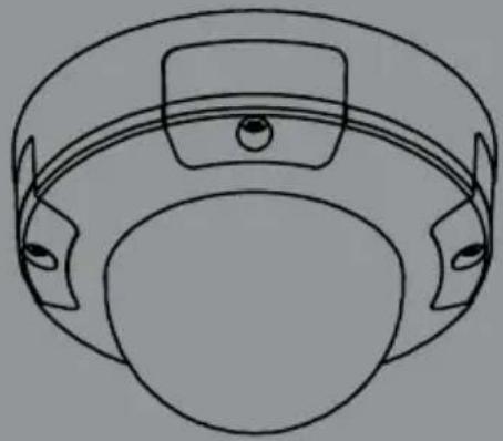
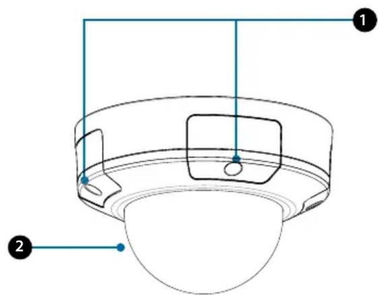
Hardware Overview
| 1 Cover Screws | These four screws can be removed with the included wrench. |
| 2 Protective Cover | Protects the camera lens assembly from the environment. |
| 3 Ethernet Port | RJ-45 connector for Ethernet which can also be used to power the camera using Power over Ethernet (PoE). |
| 4 Power Port | Connects to an optional 12 V / 1.5 A power adapter (not included). |
Hardware Overview
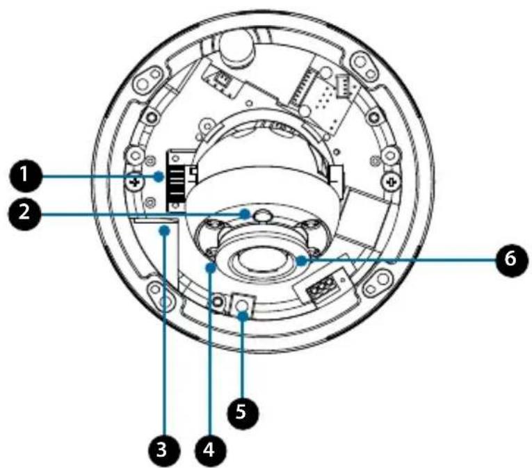
| 1 | Tilt Lock Screw | Can be loosened to adjust the camera's tilt angle. |
| 2 Light Sensor | Detects lighting levels and switches between day and night mode accordingly. | |
| 3 | microSD Card Slot | Insert a microSD card for onboard storage of snapshots and video. |
| 4 IR LEDs Provide illumination for low-light environments. | ||
| 5 Reset Button | Press and hold this button down for 10 seconds to reset the camera to factory default settings. | |
| 6 Camera Lens Camera lens to record video of the surrounding area. | ||
Configuring the Camera
Insert the included CD into your computer's CD-ROM drive to begin the installation. If the Autorun function on your computer is disabled, or if the D-Link Launcher fails to start automatically, click the Windows button, type D:\autorun.exe (where D: represents the drive letter of your CD-ROM drive), and press Enter.
Note: You can also go to the D-Link website to download the Setup Wizard in the
Downloads section for your product model.
Click Setup Wizard and follow the instructions to install the Setup Wizard.
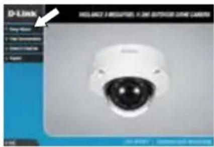
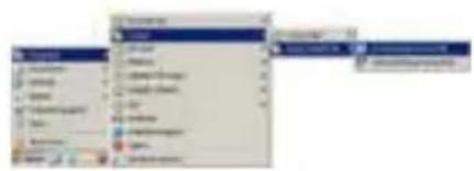
Click on the D-Link Setup Wizard SE icon that was created in your Windows Start menu (Start > D-Link > Setup Wizard SE).

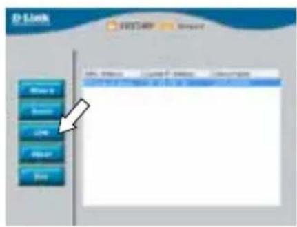
The Setup Wizard will appear and display the MAC address and IP address of your camera(s). If you have a DHCP server on your network, a valid IP Address will be displayed. If your network does not use a DHCP server, the network camera's default static IP 192.168.0.20 will be displayed.
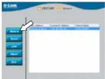
Select your camera, then click the Wizard button to continue.
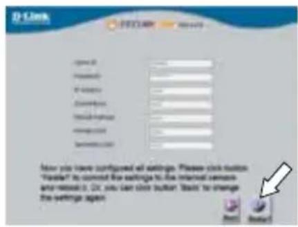
Enter the Admin ID and password. When logging in for the first time, the default Admin ID is admin with the password left blank.

Click the checkboxes if you wish to change the admin ID and password for the camera, and enter the new ID and password you wish to use.
Click Next to continue.
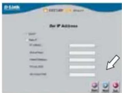
Select DHCP if your camera obtains an IP address automatically from a DHCP server such as a router. Select Static IP if you want to manually enter the IP settings for the camera.
Click Next to continue.
Take a moment to confirm your settings and click Restart when you are done.
Viewing Your Camera via Web Browser
Click on the D-Link Setup Wizard SE icon that was created in your Windows Start menu (Start > D-Link > Setup Wizard SE).
Select the camera and click Link to access the web configuration.
The Setup Wizard will automatically open your web browser to the IP address of the camera.
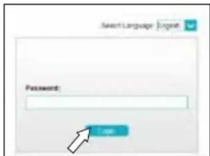
The first time you connect to the camera, you will be asked to set a password for the administrator account. After entering a password, click Save.
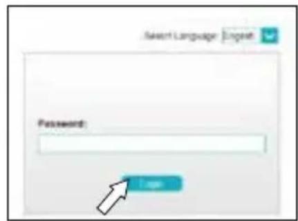
OR
Under Password, enter the same password that you configured during setup and click Login to continue.
This section displays your camera's live video. You can quickly select your screen mode and video profile and view or operate the camera. For additional information about web configuration, please refer to the user manual included on the CD-ROM or the D-Link website.

Mounting Instructions
It is highly recommended that you configure and test your camera before mounting it.
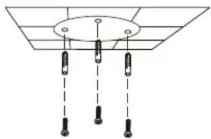
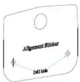
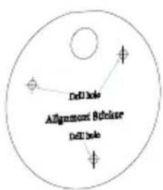
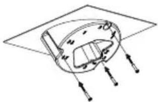
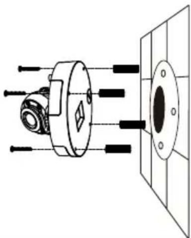
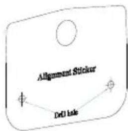
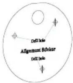
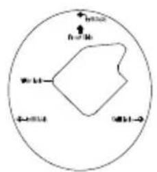
Place the mounting sticker where you want to position the camera.
Use a 6mm drill bit to make the required holes approximately 25mm deep, then insert the wall anchors into the holes.
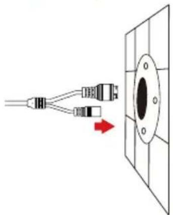
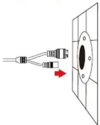
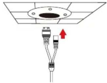
If you are running the camera cables through the wall, drill a hole in the center and pull the cables through the hole.
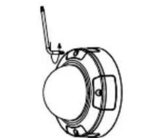
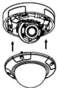
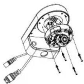
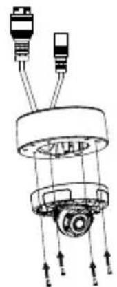
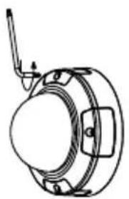
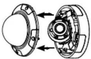
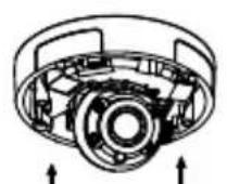
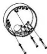
Use the included wrench to loosen the 4 screws on the top of the camera, then lift the camera cover off.

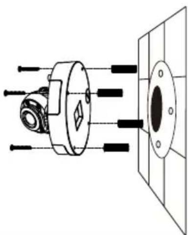
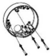
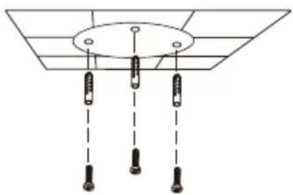
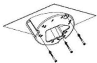
Use the screws provided to mount the camera to the wall.
If you are running the camera cables out the side of the camera, guide the camera cables through the cable channel on the base.
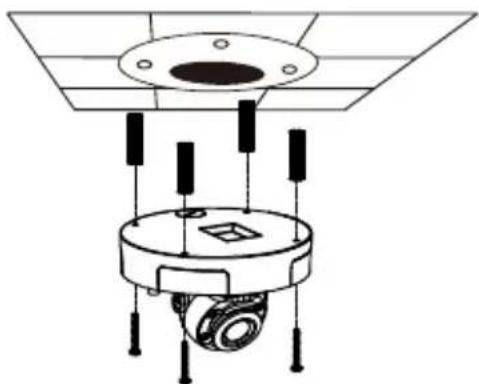
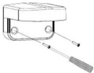
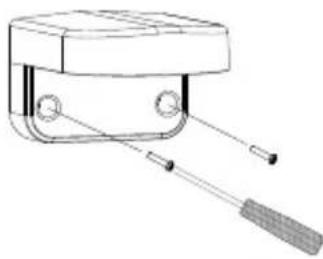
If you are mounting the camera to the ceiling, use a athead screwdriver to remove the plastic hole cover from the bottom of the base, then guide the cables through the bottom.
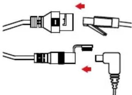
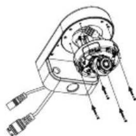
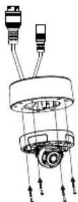
Connect the power and Ethernet cables, or just the Ethernet cable if you are using a PoE connection.
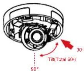
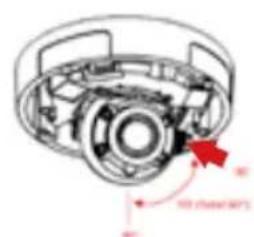
Loosen the adjustment screw on the side of the lens assembly, then re-tighten it after adjusting the lens assembly to the desired vertical angle. The camera supports from 30^ to 90^ of tilt.
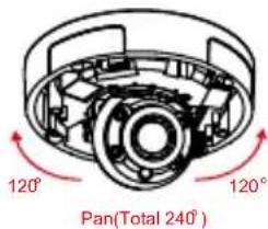
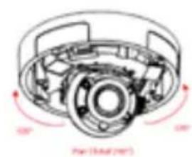
You can also adjust the pan within a -120^ to 120^ range by rotating it clockwise or counter-clockwise.
When you are done adjusting the camera's angle, put the inner cover back into place.
Note: The camera has a limited range of motion; if it stops when you are adjusting it, do not attempt to rotate or tilt the camera any further in that direction.
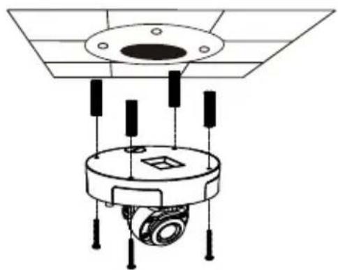
Use the screws provided to mount the camera to the ceiling.
Re-attach the camera cover.

Using the DCS-37-1 Mount (optional)
Place the DCS-37-1 mounting sticker in the desired location, then use a 6 mm drill bit to drill the required holes 25mm deep and insert the wall anchors into the holes. If you plan to pass cables through the wall, you will also need to drill a hole for the cable channel.
Note: The camera in the corresponding graphics may be different from your product, but the basic process is the same.
Use the provided screws to mount the DCS-37-1 to the wall.
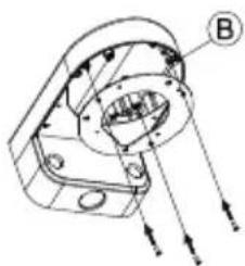
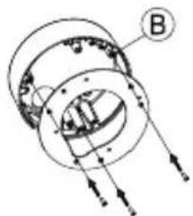
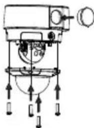
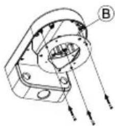
Guide the camera connectors through the back or bottom cable channel on the DCS-37-1. Then screw the mounting plate to the bracket using the set of mounting holes marked B.
Remove the cover from the camera.
Use the provided screws to mount the camera to the DCS-37-1, then adjust the angle and rotation of the camera as desired using the tilt lock screw.
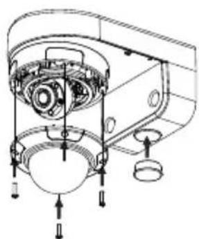
Attach the camera cover.
If you are passing the camera cables through the wall, place the rubber stopper into the bottom cable channel on the mount to seal it.

Using the DCS-37-2 Mount (optional)
Place the DCS-37-2 mounting sticker in the desired location, then use a 6mm drill bit to drill the required holes 25mm deep and insert the wall anchors into the holes. If you plan to pass cables through the ceiling, you will also need to drill a hole for the cable channel.
Note: The camera in the corresponding graphics may be different from your product, but the procedure is the same.
Use the provided screws to mount the DCS-37-2 to the wall using the inner mounting holes.
Guide the camera connectors through the back or side cable channel on the DCS-37-2. Use the provided screws to mount the camera to the DCS-37-2 using the set of mounting holes marked B.
Remove the cover from the camera.
Use the provided screws to mount the camera to the DCS-37-2, then adjust the angle and rotation of the camera as desired using the tilt lock screw.
Attach the camera cover.
If you are passing the camera cables through the ceiling, place the rubber stopper into the side cable channel to seal it.
Using the DCS-37-3 Mount (optional)
Place the DCS-37-3 mounting sticker in the desired location, then use a 6 mm drill bit to drill the required holes 25 mm deep and insert the wall anchors into the holes. If you plan to pass cables through the ceiling, you will also need to drill a hole for the cable channel.
Note: The camera in the corresponding graphics may be different from your product, but the procedure is the same.
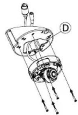
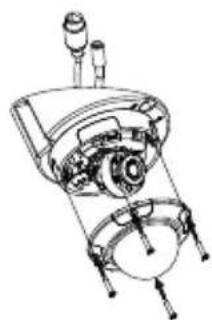
Use the provided screws to mount the DCS-37-3 to the ceiling using the inner mounting holes.
Remove the cover from the camera.
Guide the camera connectors through the bottom cable channel on the DCS-37-3. Use the provided screws to mount the camera to the DCS-37-3 using the set of mounting holes marked D.
Remove the cover and adjust the angle and rotation of the camera as desired, then put the cover back in place. Screw the camera cover back in place.
Make sure the rubber stopper is in the side cable channel to seal it.


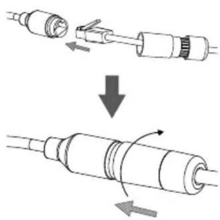
Waterproofing Your Installation
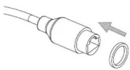
To waterproof your camera installation, follow the instructions below. Round Ethernet cable, a crimping tool, and RJ-45 plugs are required for this procedure.
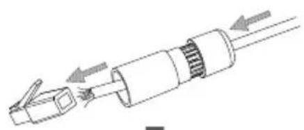
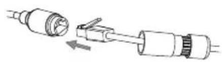
Place the washer around the base of the Ethernet connector as shown.
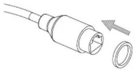
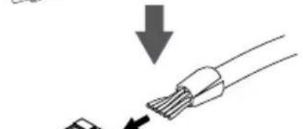
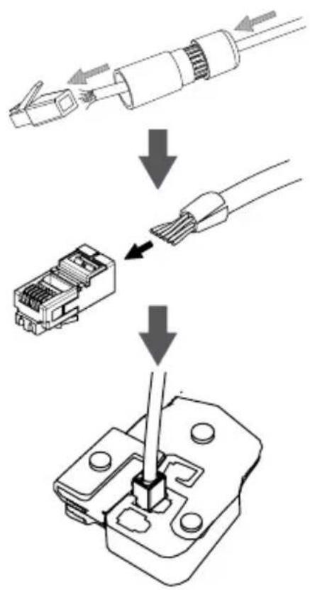
Thread bare Ethernet cable through the waterproof connector as shown.
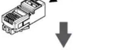
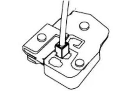
Crimp an RJ-45 connector onto the end of the cable.
Connect the other end of the Ethernet cable to the camera's Ethernet port.
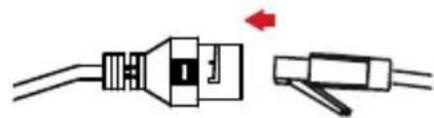
Connect the RJ-45 plug into the Ethernet connector, then screw the waterproof connector to the Ethernet connector by turning it clockwise for about a half-turn.
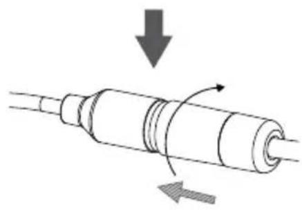
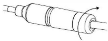
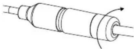
Screw the back part of the waterproof connector clockwise until there is a tight seal around the Ethernet cable.
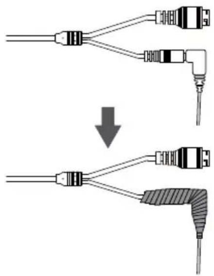
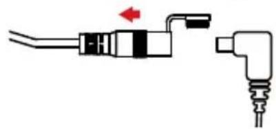
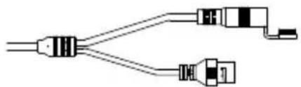
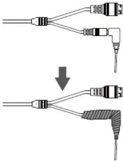
If you are using PoE to power your camera, use the attached rubber power connector cover to seal the power connector.
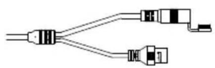
If you are using a power adapter(not included) to power your camera, wind waterproof tape around the connection in an overlapping manner to cover it.
Additional Information
Additional help and product information is available online at http://www.dlink.com.
Warranty Information
Please visit http://warranty.dlink.com/ for warranty information for your region.
KpaTkoe pyKOBoIDCTBO NO yCTaHOBKe
Данhoe руковдъв соржп.T OCHOBьг e nHCTpyKcNn no yctaHOBKe KaMepb DCS-4633EV.Дя полчeня доюнтельнои nHΦopMaци nNo HactrpoIke KaMepb o6paTntecb K rykoBODCTBy noIb3ObaTeЯ Na CD-dncke N3 KOMJIeKta NOCTaBKn nII NdoCTyINHomy Ha Web-caite D-Link.
KoMnJIeKT NOcTaBKN
Bheunra ceTeBa kamepa DCS-4633EV
BodonepoHuaembIKoHHeKTopJaKa6eJia
KOMnJIeKT JIa MOHTaJa
CD-ДИСС рукововсВOM NOьБОВаTeЯ И пограMMыМ obecпeунем
KpaTkoe pyKOBoDCTBO no yCTaHOBKe
Ecni YTO-JI60 n3 nepeuHcJIeHHoro OTCyTCTByET, NOxJaYnCTa, o6paTntecb K NoCTaBUnKy.
MepbI 6e3oNaChOCTn:
Bo n36eXaHn npekpaueHnraPaHTn yCTaHOBky n 06cnyxHBnne DOJXHb I pOBOaNTb ceTnΦuNpOBaHHbIe CneuaJIInCTbI B COOTBeTCTBnC peRHOHaJIbHbIMn HOpMaMn n PpaBnJaMn.
Hajmte Next (Jaee), TTo6bI IpeeTn Ha CJeNyUuO CTpaHnU.

PpOBepbTe HacTpoiKn HaXMMTe Restart (Ipepe3anyCTntb).

MaCTep yCTaHOBKn aBTOMaTHueCKn OTKpoeT Web-6pay3ep n CTpaHnCy KaMepbl.
Pn nepBOM NOdkHoueHH K Kamepe Bam Heo6xOIMO 3aTaB napOB dny yueTHo 3aNNcN aDMHNCTpaTopa. BBeNTe napOB n HaxMnte Save (CoXpaHTb).
PnKpEnIte HnPaBIAUoIcTKepe Ha MeCTO, rIe PnHaHpyETcay yCTaHOBHTb KaMepy.
PpocBepnTe OTBepCTnR rny6HNo np6n3nteIbHO 25 MM CBePOM DnaMeTpOM 6 MM. 3aTeM BCTaBbTe B OTBepCTnR anKepbl.
Ecn Tpe6yeTc npoOxntb Ka6eN dna KamepbI B CTeHe, npcBepnTE OTBepCTne B ceHTpe n IpOTAHnTE Ka6eN uep3 3TO OTBepCTne.
C NOMOUIBXBODAIEROB KOMNNEKT NOCTABKN KJIIOVA Ocna6bTe 4 BnHTa Ha BepxHeu Yactu Kopnyca KaMepbl IN CHIMITE 3aUHTHyO KpbIUKy.
YcTaHOBnTe KaMepy Ha CTeHy C NOMOuBxOJaXx B KOMJIeKTI NOCTaBKn BNHTOB.
Ecnn dny KaMepbl Tpe6yeTc npONoXHTb Ka6en C BHeuHne CTOpOHbl, npOTAHnTe INx Uepe3 KaHaJI B OCHOBaHN KAMEpbI.
Пр MOТахе KaMepbl Ha NOTOLke NcNoJIb3yIte OTBepTKy ДЯ ИЗВЛeЧЕня 3aUHTHоN ПlaCTNKOBОн HAKnAДКВ OCHOBAHи KaMepbl, 3aTeM ПpoTЯHNTe Ka6eNi Yepe3 OTBepCTne.
IopKnIOUHTe Ka6eNn PntaHnN n Ethernet. Pnp NcNoJIb3OBAHn TexHOJIoRn PoE IopKnIOUHTe TOnbKO Ethernet-ka6eB.
Ocna6bTe pepyHnpoBOHyB BnHT, HaxoJusnCs C60ky o6beKtNa KaMepbl, HAcTPOte Tpe6yEmbl yrO1 no BePTNKaII N 3aTaNITE BnHT. KaMepa nOdEprXnBaET yrO1 HaKIOHa ot 30^ do 90^ .
Takke Bo3MOxHa HacpoKa yIa nO rOpN3oHTaII O T-120° Do 120°. OtperyIInPoBaT b yroI MoXHO C NOMOuH NOBOPa o6bektNa IIO YACOB IN IPOTN B YACOBI CTpeKN.
BHMaHHe: dHaNa3OH nepMeUeHnObEKTINBa KaMepbl OrpaHnueH; ecn OHa OCTaHOBTcR BO BpeM BbIOJIHeHn peYInpOBKn, He nbTaIteCb IOBOpauNBaTb IIn HaKIOHrTb KaMepy DaIbIe B 3TOM HApPaBJeHn.
IcnoJIb3yIte BnHTbl N3 KOMNKeKta NoCTaBKn, YTO6bl 3aKpeNTb KaMepy Ha NOTOLke.
YcTaHOBnTe n 3aKpeNITe 3aUHTHyO KpbIuKy.
IcnoB3y BxOJaUne B KOMnNeKT NoCTaBKn BnHTbI, npKpeNte DCS-37-1 K cTeHe.
ПрOTЯнITE ka6eJIc pa3beMaMn chepe3 HIXHni IIN 6OKOBoi Ka6eIbHbI KaHaJI Ha DCS-37-1. ИспОЛьЗУВИТыI, 3aKpeIITe MOHTaXHyIO ПЯТу K OTBepCTnAМ, OTMeueHHbIM 3HaKOM B, Ha DCS-37-1.
CHIMTE 3aUHTHyIO KpbIuKy KaMepbl.
IcnoJb3yra BnHtbi N3 KOMNJIeKTA NOCTaBKN, npNKpeNITe KaMepy K DCS-37-1, 3aTeM oTpeRyInpYte nOIOKeHne O6beKTnBa.
YCTaHOBInTe 3aIHTHyIO KpbIiKy KaMepbl.
Y6eIHTecb, YTO pe3HOBa 3aRnyuKa HaxoITcB HnXHem Ka6eIbHOM KaHaNe, ecIn Ka6eN KamepbI npoxoJr Tpe3 CTehy.
YCTaHOBnTe 3aIHTHyO KpbIiKy KaMepebl.
Y6eNTecb, YTO pe3HOBa 3aRnyuKa HaxoNTcB B 6OKOBOM Ka6eNbHom KaHaJe, ecn Ka6eN KamepbI npoxoJr Tpe3 NOTOJok.


CHIMTE 3aunthyIO KpbIuKy KaMepbl.
IpoTaNHe Ka6eHc pa3bEmaMnYepe3 ceHTpaNbHbIKa6eHbHk KaHaHa DCS-37-3. NcNoJIb3yJte BxoJaUeB KOMNKeT NOCTaBKn BVHTbI IJa KpeJIeHnKaMepbKOTBepCTnM, OTMeueHHbIM D, Ha DCS-37-3.
OtperynupyIte noJoxKeHne o6bekTnBa, nocNe yero yCTaHOBInTe 3aunTHyIO KpbIuKy. 3akpeiNte 3aunTHyIO KpbIuKy npn NOMOUs BNHTOB.
y6eNTecb, yTO pe3HOBa 3aIpyka HaxoITcB 6OKOBOM Ka6eNbHOM kaHaJe.
BodonepnoHuaemoctb kamepbI
YTObI ObecneuHb BDOHOePOnHuaemocTb KaMepbl, CJeDyIte npNBeDeHHbIM HnKe INCTpyKcIaM. DnA 3ToI npOeDpybl nOTpe6yIOTc KpyrIbI Ethernet-Ka6eJIb, INCTpyMeHT dIra OBXIMa N KOHNekTopbl RJ-45.
YCTaHOBInTe yIINOTHInTeIbHyIO npOKnAdKy Ha pa3bEm RJ-45, KAK NOKa3aHo Ha pncyHKe.
IpoTAHnTe Ethernet-Ka6eB Yepe3 BDOHepOnHuaembIKOHHeKTop, KaK noka3aHo Ha pncyHke.
BcTaBbTe Ka6eJb B KOHHeKTop RJ-45 n o6OxMnTe.
IopKnHouHTe npuro Koneu Ethernet-Ka6eJK Ethernet-nOpTy KaMepbl.
CoedHnTe KOHKeTOp c pa3bEmOM RJ-45. 3aKpyTne BOHOHePPOHuaEMbI KOHKeTOp, NOBepHyB erO np6bn3nteJbHo Ha non-obopota no yacobov CTpeNke.
IobepHnte HxKHOU qactb BDOHe npOnucaemoro KOHKeToppa no yacOBn cTepeKe dJa oBeceueHn repMeTuHocTt Ethernet-kaBela.
Ecnn noadaa nntaHna KaMepy ocuueCTBJeTcno TexhONorn PoE, INCIOJIb3yIte BXOJaUyIO B KOMJIeKT NOCTaBKn pe3INHOByU 3aIpykU dny pa3beMa NIHTaHn.
Ecnn noa a ntaHna Ha kamepy ocuueCTBnaeTc nomoubno aanTepa nntnna (He BXoNT B KOMnIeKT nocTaBn),ncnbl3yIne CneunalbHyIO JeHTy dnnrepeMtn3aunC cJeIbIO npedOTbpaueHnnaonadaHnBaHa Ha coeINHeHne.
He yctaHaBJIbAitye yCTpoiCTBO B 3OHaX C BJIaXHOCTbIO u yPOBHeM 3aIrp3HeHnRA BO3dyxa CBblwe 80% ; a TaKke B O6JaCTn NOBblseHHoro NcnapeHn I napoo6pa3OBaHnI nn ycJIeHHo BV6paCNI.
He nCnoIb3yIte yCTpoIcTBO C NOBpeJdeHbIM KOpnycom. TemnepaTypa OKpykaIOUeI cpeIb B HeNOCpeIcTBeHHoN 6JIIN3OCTN OT yCTpoIcTBA N BHyTpN erO KOpnyCa DOJXHa COOTBeTCTBOBaTb yKa3aHHoN B TEXHnueCKNX XapaKTePnCTNKax yCTpoIcTBA.
3JIeKtpOnHtAHnE DOJXHO COOTBeTCTBOBaTb napaMeTpam 3JIeKtpOnHtAHnIyKa3aHHbIM B TexHnuecknx XapaKTePncTnKax yCTpoiCTBa.
Bo n36exaHne noBpeXdEHHa MaTpNcbl He HnpaBnTe oBeKtNB BndeOKaMepbHa ouHe bApKHe oBeKtbl n CoHNcE.
He BCKpbIbAaTe KOpnyc ycTpoiCTBa! Npeed OuncTKoY cTPOiCTBa OT 3aqr3HeHm I nbIIN OTKIOUHTe PNTaHne ycTpoiCTBa. YdaJIte nbIIN C NOMOuB BnaXHOI caNΦeTKn. He nCnoJIb3yIte JxIDKne/a3pO3OJbHbIe OuncNTeJI NII MArHHTbIe/ CTaTnueckne ycTpoiCTBa dJa OuncTkn. N36eAaTe nonaDaHnB bLaRn B ycTPOICTBO.
Cpok cnjxkbiyyctpoiCTBa-2 roda.
TapaHTnHbI nepNOI NCHCJAEcra C MOMeTa npNo6peTeHnY cTpoiCTBa y oOuHaJIbHOrO dInepa Ha TeppntOpn PocCnn I cTpaH CHr n coCTaBJIeT OOnH rOd. BHe 3aBNCIMoCTn OT DaTbI IpOdaXn rapaHTnHbI cPOK He MoKET pReBbIaTb 2 rOda C DaTbI IpOu3BOIDCTBa N3DeJIy, KOtopa ONpeJeJIeTcra No 6 (roD) n 7 (MeCau) ZnΦpam cepuHoro Homepa, yKa3aHHOrO Ha NaKJIeKe c TexHnueCKIMn DaHHbIMn.
Год: 9 - 2009, A - 2010, B - 2011, C - 2012, D - 2013, E - 2014, F - 2015, G - 2016, H - 2017.
Mecya: 1 - RaHbapb, 2 - fpeBpaIb, ..., 9 - cHTra6pb, A - OKT86pb, B - Ho86pb, C - Deka6pb.
AnMaTbI, KypMaHaFa3bI K-ci,143 y
Ten.: +7 (727) 378-55-90
E-mail: almaty@dlink.ru
zuiuunui
bpuu,unpuu2tu 3-pp
puunuufuu, 23/5
2bn. +374 (10) 39-86-67
E1. qnuu.info@dlink.am
Latvija
Riga, Lielirbes iela 27
Tel.: +371 (6) 761-87-03
E-mail: info@dlink.lv
Lietuva
Vilnius, Zirmunu 139-303
Tel.: +370 (5) 236-36-29
E-mail: info@dlink.lt
Eesti
E-mail: info@dlink.ee
Türkiye
Uphill Towers Residence A/99
Atasehir /ISTANBUL
Tel: +90 (216) 492-99-99
Email: info.tr@dlink.com.tr
Guia de instalação
Regulatory Statements (Only for Class A products)
Federal Communication Commission Interference Statement
This equipment has been tested and found to comply with the limits for a Class A digital device, pursuant to part 15 of the FCC Rules. These limits are designed to provide reasonable protection against harmful interference when the equipment is operated in a commercial environment. This equipment generates, uses, and can radiate radio frequency energy and, if not installed and used in accordance with the instruction manual, may cause harmful interference to radio communications. Operation of this equipment in a residential area is likely to cause harmful interference in which case the user will be required to correct the interference at his own expense.
Non-modification Statement
Any changes or modifications not expressly approved by the party responsible for compliance could void the user's authority to operate the equipment.
Caution
This device complies with Part 15 of the FCC Rules. Operation is subject to the following two conditions:
(1) This device may not cause harmful interference, and (2) this device must accept any interference received, including interference that may cause undesired operation.
Innovation, Science and Economic Development Canada (ISED) Statement:
This Class A digital apparatus complies with Canadian ICES-003.
CE EMI Class A Warning
This equipment is compliant with Class A of CISPR 32. In a residential environment this equipment may cause radio interference.
English
CEEMIClassAWARNING
This equipment is compliant with Class A of CISPR 32. In a residential environment this equipment may cause radio interference.
SAFETY INSTRUCTIONS
The following general safety guidelines are provided to help ensure your own personal safety and protect your product from potential damage. Remember to consult the product user instructions for more details.
- Static electricity can be harmful to electronic components. Discharge static electricity from your body (i.e. touching grounded bare metal) before touching the product.
- Do not attempt to service the product and never disassemble the product. For some products with a user replaceable battery, please read and follow the instructions in the user manual.
- Do not spill food or liquid on your product and never push any objects into the openings of your product.
- Do not use this product near water, areas with high humidity, or condensation unless the product is specifically rated for outdoor application.
- Keep the product away from radiators and other heat sources.
- Always unplug the product from mains power before cleaning and use a dry lint free cloth only.
DISPOSING AND RECYCLING YOUR PRODUCT

This symbol on the product or packaging means that according to local laws and regulations this product should be not be disposed of in the household waste but sent for recycling. Please take it to a collection point designated by your local authorities once it has reached the end of its life, some will accept products for free. By recycling the product and its packaging in this manner you help to conserve the environment and protect human health.
CE EMI KLASSE A-WAARSCHUWING
AFVALVERWERKING EN RECYCLING VAN UW PRODUCT

MISE AU REBUT ET RECYCLAGE DE VOTRE PRODUIT

VIDVÖRUN FYRIR CE EMI FLOKK A
UTYLIZACJA I RECYKLING PRODUKTU

Slovenian [Slovenski]
OPOZORILO CE EMI ZA RAZRED A
DESECHAR Y RECICLAR EL PRODUCTO

CE EMI KLASS A-VARNING
This D-Link product includes software code developed by third parties, including software code subject to the GNU General Public License ("GPL") or GNU Lesser General Public License ("LGPL"). As applicable, the terms of the GPL and LGPL, and information on obtaining access to the GPL code and LGPL code used in this product, are available to view the full GPL Code Statement at:
The GPL code and LGPL code used in this product is distributed WITHOUT ANY WARRANTY and is subject to the copyrights of one or more authors. For details, see the GPL code and the LGPL code for this product and the terms of the GPL and LGPL.
Written Offer for GPL and LGPL Source Code
Where such specific license terms entitle you to the source code of such software, D-Link will provide upon written request via email and/or traditional paper mail the applicable GPL and LGPLsource code files via CD-ROM for a nominal cost to cover shipping and media charges as allowed under the GPL and LGPL.
Please direct all inquiries to:
Email:
GPLCODE@dlink.com
Snail Mail:
Attn:GPLSOURCEREQUEST
D-Link Systems, Inc.
Fountain Valley, CA 92708
Notes
Notes
Notes
Notes
D-Link

Ver. 1.01(WW)_90x130
2018/10/08
0420125/1-DL

- Quick Installation Guide
- Vigilance 3 Megapixel H.265 Outdoor Dome Camera
- Package Contents
- Safety Notice:
- Hardware Overview
- Configuring the Camera
- Viewing Your Camera via Web Browser
- OR
- Mounting Instructions
- Using the DCS-37-1 Mount (optional)
- Using the DCS-37-2 Mount (optional)
- Using the DCS-37-3 Mount (optional)
- Waterproofing Your Installation
- Additional Information
- Warranty Information
- KpaTkoe pyKOBoIDCTBO NO yCTaHOBKe
- KoMnJIeKT NOcTaBKN
- MepbI 6e3oNaChOCTn:
- BodonepnoHuaemoctb kamepbI
- Guia de instalação
- Regulatory Statements (Only for Class A products)
- Federal Communication Commission Interference Statement
- Non-modification Statement
- Caution
- Innovation, Science and Economic Development Canada (ISED) Statement:
- CE EMI Class A Warning
- English
- CEEMIClassAWARNING
- SAFETY INSTRUCTIONS
- DISPOSING AND RECYCLING YOUR PRODUCT
- CE EMI KLASSE A-WAARSCHUWING
- AFVALVERWERKING EN RECYCLING VAN UW PRODUCT
- MISE AU REBUT ET RECYCLAGE DE VOTRE PRODUIT
- VIDVÖRUN FYRIR CE EMI FLOKK A
- UTYLIZACJA I RECYKLING PRODUKTU
- Slovenian [Slovenski]
- OPOZORILO CE EMI ZA RAZRED A
- DESECHAR Y RECICLAR EL PRODUCTO
- CE EMI KLASS A-VARNING
- Written Offer for GPL and LGPL Source Code
- Email:
- Snail Mail:
- Notes
- D-Link
Brand : D-LINK
Model : DCS4633EV
Category : Surveillance Camera