JN3201J - Scissors MAKITA - Free user manual and instructions
Find the device manual for free JN3201J MAKITA in PDF.

| Brand | Makita |
| Model | JN3201J |
| Product Type | Nibbler (scissor type) |
| Applications | Cutting sheet metal and stainless steel |
| Maximum cutting capacity | Steel up to 400 N/mm²: 3.2 mm; up to 600 N/mm²: 2.5 mm; up to 800 N/mm²: 1.0 mm; Aluminum up to 200 N/mm²: 3.5 mm |
| Number of strokes per minute | 1 min⁻¹ |
| Total length | 225 mm |
| Net weight | 3.4 kg |
| Minimum cutting radius | Outer edge: 128 mm; inner edge: 120 mm |
| Power supply | Single-phase mains, double insulation (class II) |
| Sound pressure level | 101 dB(A) |
| Sound power level | 109 dB(A) |
| Vibration emission | 10.0 m/s² (sheet metal cutting) |
| Carbon brush maintenance | Replace when wear mark is reached |
| Matrix sharpening | After approximately 300 m of cutting (3.2 mm steel) |
| Punch replacement | After approximately 150 m of cutting (3.2 mm steel) |
| Lubrication | Machine oil on the cutting line (every 10 m for steel/stainless steel; constant lubrication for aluminum) |
| Included accessories | Wrench, hex wrench, half washer, matrix holder, punch, matrix |
Frequently Asked Questions - JN3201J MAKITA
User questions about JN3201J MAKITA
0 question about this device. Answer the ones you know or ask your own.
Ask a new question about this device
Download the instructions for your Scissors in PDF format for free! Find your manual JN3201J - MAKITA and take your electronic device back in hand. On this page are published all the documents necessary for the use of your device. JN3201J by MAKITA.
USER MANUAL JN3201J MAKITA
GB Nibbler Instruction Manual
| F | Grignoteuse | Manuel |
| D Knabber Betriebsanleitung | ||
| I Roditrice Istruzioni d’Uso | ||
| NL Knabbelschaar Gebruiksaanwijzing | ||
| E Roedora Manual de Instrucciones | ||
| P Tesoura Punção Manual de Instruções | ||
| DK Pladestanser | Brugsanvisning | |
| GR Zouμποψάλιδο | Οδηγίες χρήσεως | |
| TR Nibler | Kullanma kılavuzu | |
JN3201
natural_image
Technical line drawing of a mechanical power tool (no text or symbols present)

013355 013356
1

013357 013358 4
3
natural_image
Line drawing of a hand operating a manual power tool (no text or symbols present)004785 013259
5
natural_image
Line drawing of a hand operating a mechanical power tool (no text or symbols)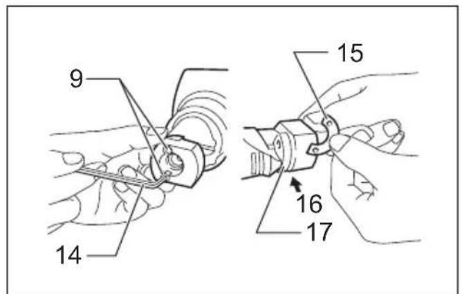
7
013360 004792
8
9
004793 004791
natural_image
Pure mechanical diagram showing a spring-loaded component with no text or symbols11 12
001145 013361
ENGLISH (Original instructions)
| Explanation of general view | ||
| 1 Stainless steel gauge: 2.5 mm (3/32") | 9 Screw | 18 Grind/sharpen; 0.3 – 0.4 mm (1/64") |
| 2 Mild steel gauge: 3.2 mm (1/8") | 10 Cutting edge | |
| 3 Switch trigger | 11 Groove | 19 Remove dull portion |
| 4 Lock button | 12 Punch holder | 20 3.5 – 4.0 mm (1/8" – 5/32") |
| 5 Wrench | 13 Pin | 21 Limit mark |
| 6 Lock nut | 14 Hex wrench | 22 Screwdriver |
| 7 Die holder | 15 Washer | 23 Brush holder cap |
| 8 Punch | 16 Insert washer in between | |
| 17 Die | ||
SPECIFICATIONS
| Model JN3201 | ||
| Max. cutting capacities | Steel up to 400 N/mm ^2 | 3.2 mm / 10 ga |
| Steel up to 600 N/mm ^2 | 2.5 mm / 13 ga | |
| Steel up to 800 N/mm ^2 | 1.0 mm / 20 ga | |
| Aluminum up to 200 N/mm ^2 | 3.5 mm / 10 ga | |
| Min. cutting radius | Outside edge 128 mm | |
| Inside edge 120 mm | ||
| Strokes per minute (min ^-1 ) 1,300 | ||
| Overall length 225 mm | ||
| Net weight 3.4 kg | ||
| Safety class /II | 回 | |
- Due to our continuing program of research and development, the specifications herein are subject to change without notice.
- Specifications may differ from country to country.
• Weight according to EPTA-Procedure 01/2014
ENE037-1
Intended use
The tool is intended for cutting sheet steel and stainless sheet steel.
ENF002-2
Power supply
The tool should be connected only to a power supply of the same voltage as indicated on the nameplate, and can only be operated on single-phase AC supply. They are double-insulated and can, therefore, also be used from sockets without earth wire.
GEA010-2
General Power Tool Safety Warnings
WARNING Read all safety warnings, instructions, illustrations and specifications provided with this power tool. Failure to follow all instructions listed below may result in electric shock, fire and/or serious injury.
Save all warnings and instructions for future reference.
The term “power tool” in the warnings refers to your mains-operated (corded) power tool or battery-operated (cordless) power tool.
GEB028-2
NIBBLER SAFETY WARNINGS
- Hold the tool firmly.
- Secure the workpiece firmly.
- Keep hands away from moving parts.
- Edges and chips of the workpiece are sharp. Wear gloves. It is also recommended that you put on thickly bottomed shoes to prevent injury.
- Do not put the tool on the chips of the workpiece. Otherwise it can cause damage and trouble on the tool.
- Do not leave the tool running. Operate the tool only when hand-held.
- Always be sure you have a firm footing. Be sure no one is below when using the tool in high locations.
- Do not touch the punch, die or the workpiece immediately after operation; they may be extremely hot and could burn your skin.
- Avoid cutting electrical wires. It can cause serious accident by electric shock.
SAVE THESE INSTRUCTIONS.
WARNING:
DO NOT let comfort or familiarity with product (gained from repeated use) replace strict adherence to safety rules for the subject product. MISUSE or failure to follow the safety rules stated in this instruction manual may cause serious personal injury.
FUNCTIONAL DESCRIPTION
CAUTION:
- Always be sure that the tool is switched off and unplugged before adjusting or checking function on the tool.
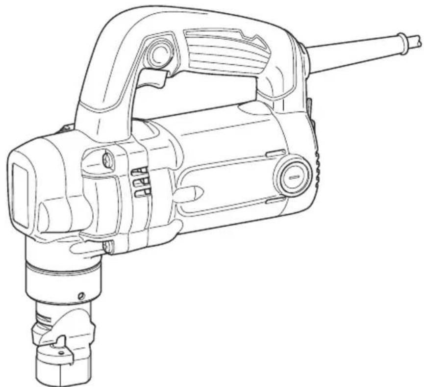
Permissible cutting thickness (Fig. 1)
The thickness of material to be cut depends upon the tensile strength of the material itself. The groove on the die holder acts as a thickness gauge for allowable cutting thickness. Do not attempt to cut any material which will not fit into this groove.
| Max. cutting capacities mm | ga | |
| Steel up to 400 N/mm ^2 | 3.2 10 | |
| Steel up to 600 N/mm ^2 | 2.5 13 | |
| Steel up to 800 N/mm ^2 | 1.0 20 | |
| Aluminum up to 200 N/mm ^2 | 3.5 10 |
006439
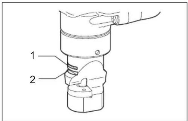
Switch action (Fig. 2)
CAUTION:
- Before plugging in the tool, always check to see that the switch trigger actuates properly and returns to the "OFF" position when released.
- Switch can be locked in "ON" position for ease of operator comfort during extended use. Apply caution when locking tool in "ON" position and maintain firm grasp on tool.
To start the tool, simply pull the switch trigger. Release the switch trigger to stop.
For continuous operation, pull the switch trigger and then push in the lock button.
To stop the tool from the locked position, pull the switch trigger fully, then release it.
ASSEMBLY
CAUTION:
- Always be sure that the tool is switched off and unplugged before carrying out any work on the tool.
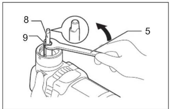
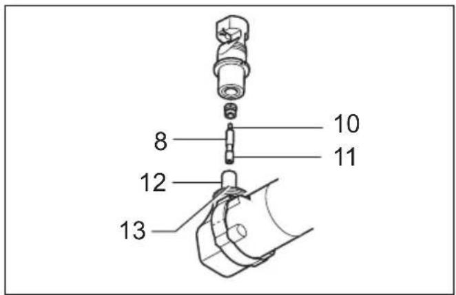
Punch replacement (Fig. 3, 4 & 5)
Fit the wrench provided onto the lock nut and tap the handle lightly with a hammer to loosen the lock nut. Take off the die holder and use a wrench to remove the screw. Then remove the punch.
To install the punch, insert it into the punch holder with its cutting edge facing forward so that the pin in the punch holder fits into the groove in the punch. Install the screw and lock nut. Then tighten them securely.
NOTE:
- When installing the screw and lock nut, be sure to tighten securely. If they become loose during operation, the tool may break down.
OPERATION
CAUTION:
- Hold the tool firmly with one hand on the main handle when performing the tool.
Pre-lubrication
Coat the cutting line with machine oil to increase the punch and die service life. This is particularly important when cutting aluminum.
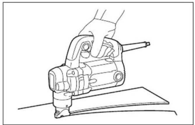
Cutting method (Fig. 6)
Smooth cutting is achieved by holding the tool upright and applying gentle pressure in the cutting direction. Apply tool oil to the punch about every 10 meters of mild steel or stainless steel to be cut. Light oil or kerosene should be used to keep an aluminum lubricated continuously. Failure to lubricate aluminum in the cut will cause chips to adhere to the tool, dulling the die and punch and increasing load on the motor.
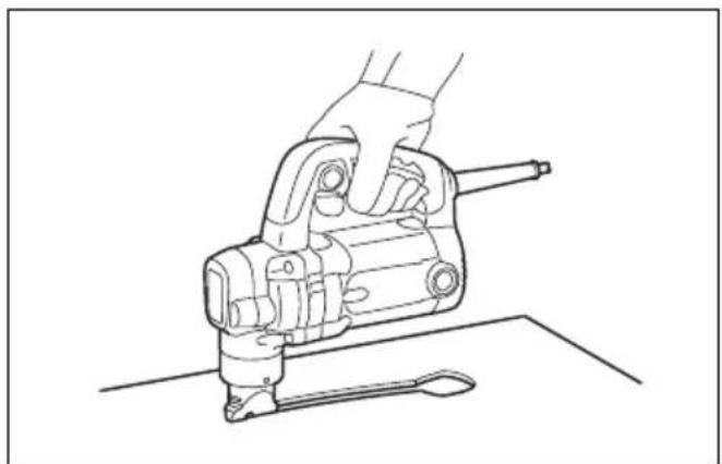
Cutouts (Fig. 7)
Cutouts can be done by first opening a round hole of about 42 mm diameter or more in the material.
Cutting stainless steel (Fig. 8)
There is more vibration when cutting stainless steel than mild steel. Less vibration and better cutting is possible by adding another washer (standard equipment) beneath the die.
Use the hex wrench provided to remove the two screws and insert the washer below the die. Replace screws and tighten securely.
MAINTENANCE
CAUTION:
- Always be sure that the tool is switched off and unplugged before attempting to perform inspection or maintenance.
- Never use gasoline, benzine, thinner, alcohol or the like. Discoloration, deformation or cracks may result.
The tool and its air vents have to be kept clean. Regularly clean the tool's air vents or whenever the vents start to become obstructed.
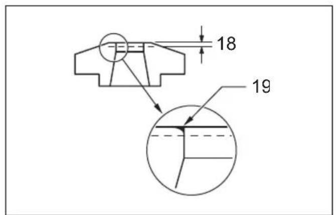
Punch & die service life (Fig. 9 & 10)
Replace or sharpen punch and die after cutting the lengths indicated in the accompanying table. Their life, of course, depends upon the thickness of materials cut and lubrication conditions.
| Punch Replace after 150 m of 3.2 mm steel sheet |
| Die Sharpen after 300 m of 3.2 mm steel sheet |
006441
When cutting is poor even after replacing the punch, sharpen the die. Grind down the dull edge shown in Fig. 9 using a grinder. After rough-grinding the dull portion, finish with a dressing stone. Stock removal should be about 0.3 to 0.4 mm.
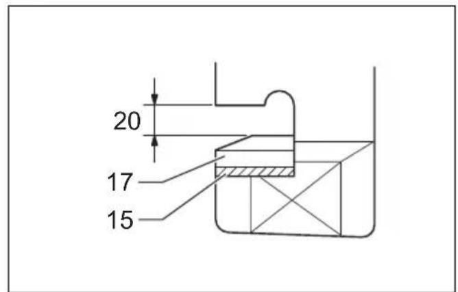
When installing ground die, a clearance of 3.5 to 4.0 mm should be obtained by attaching one or two of the washer provided, as shown in Fig. 10. Failure to have the proper clearance will result in vibration during cutting.
CAUTION:
- Secure installing screws carefully when installing. A loose screw can cause tool breakage during operation.
NOTE:
- The die can be sharpened two times. After two sharpenings, it should be replaced with new one.
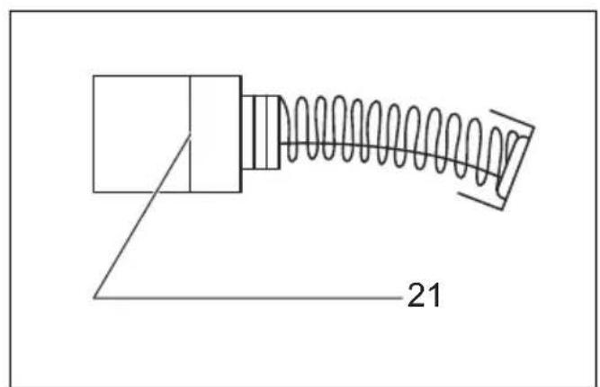
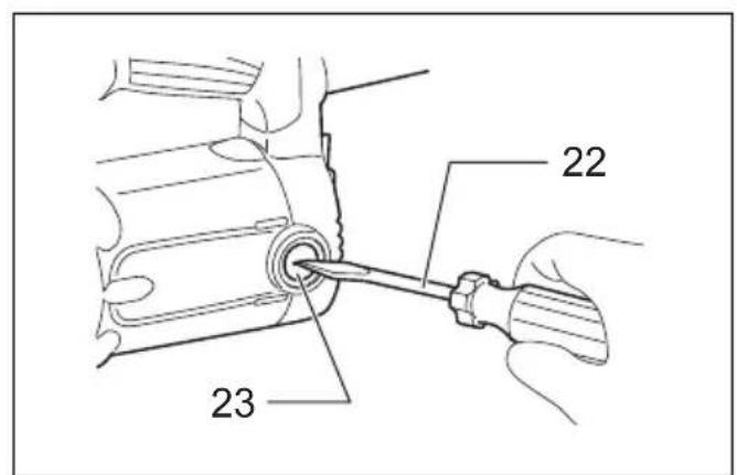
Replacing carbon brushes (Fig. 11 & 12)
Remove and check the carbon brushes regularly. Replace when they wear down to the limit mark. Keep the carbon brushes clean and free to slip in the holders. Both carbon brushes should be replaced at the same time. Use only identical carbon brushes.
Use a screwdriver to remove the brush holder caps. Take out the worn carbon brushes, insert the new ones and secure the brush holder caps.
To maintain product SAFETY and RELIABILITY, repairs, any other maintenance or adjustment should be performed by Makita Authorized Service Centers, always using Makita replacement parts.
OPTIONAL ACCESSORIES
CAUTION:
- These accessories or attachments are recommended for use with your Makita tool specified in this manual. The use of any other accessories or attachments might present a risk of injury to persons. Only use accessory or attachment for its stated purpose.
If you need any assistance for more details regarding these accessories, ask your local Makita Service Center.
• Die
- Punch
- Hex wrench
- Wrench 50
• Die height adjustment washer
NOTE:
- Some items in the list may be included in the tool package as standard accessories. They may differ from country to country.
ENG905-1
Noise
The typical A-weighted noise level determined according to EN62841-2-8:
Sound pressure level ( L_pA ): 101 dB (A) Sound power level ( L_WA ): 109 dB (A) Uncertainty (K): 3 dB (A)
ENG907-1
NOTE:
- The declared noise emission value(s) has been measured in accordance with a standard test method and may be used for comparing one tool with another.
- The declared noise emission value(s) may also be used in a preliminary assessment of exposure.
WARNING:
- Wear ear protection.
- The noise emission during actual use of the power tool can differ from the declared value(s) depending on the ways in which the tool is used especially what kind of workpiece is processed.
- Be sure to identify safety measures to protect the operator that are based on an estimation of exposure in the actual conditions of use (taking account of all parts of the operating cycle such as the times when the tool is switched off and when it is running idle in addition to the trigger time).
ENG900-1
Vibration
The vibration total value (tri-axial vector sum) determined according to EN62841-2-8:
Work mode: cutting sheet metal Vibration emission ( a_h ): 10.0 m/s ^2 Uncertainty (K): 1.5 m/s ^2
ENG901-2
NOTE:
- The declared vibration total value(s) has been measured in accordance with a standard test method and may be used for comparing one tool with another.
- The declared vibration total value(s) may also be used in a preliminary assessment of exposure.
WARNING:
- The vibration emission during actual use of the power tool can differ from the declared value(s) depending on the ways in which the tool is used especially what kind of workpiece is processed.
- Be sure to identify safety measures to protect the operator that are based on an estimation of exposure in the actual conditions of use (taking account of all parts of the operating cycle such as the times when the tool is switched off and when it is running idle in addition to the trigger time).
DECLARATIONS OF CONFORMITY
For European countries only
The Declarations of conformity are included in Annex A to this instruction manual.
Descriptif