
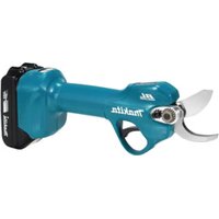
DUP362Z - Scissors MAKITA - Free user manual and instructions
Find the device manual for free DUP362Z MAKITA in PDF.

| Product type | Battery-powered pruner (scissors pair) |
| Brand | Makita |
| Model | DUP362Z |
| Power supply | 36 V DC lithium-ion battery (battery not included) |
| Maximum cutting capacity | 33 mm |
| Total length (pruner part) | 305 mm |
| Net weight (pruner part) | 0.77 - 0.82 kg |
| Compatible batteries | BL1815N, BL1820B, BL1830B, BL1840B, BL1850B, BL1860B |
| Compatible chargers | DC18RC, DC18RD, DC18RE, DC18SD, DC18SE, DC18SF, DC18SH, DC18WC |
| Sound pressure level (L_pA) | 70 dB(A) or less (uncertainty K=3 dB(A)) |
| Vibration emission (ah) | 2.5 m/s² or less (uncertainty K=1.5 m/s²) |
| Overload protection | Automatic stop in case of abnormal current |
| Overheat protection | Automatic stop, green indicator flashes |
| Total discharge protection | Automatic stop, red indicator on/flashes |
| Safety lock | Double trigger press to unlock |
| Adjustable opening angle | Selector to limit opening |
| Adjustable cutting depth | By adjustment screw (hex key) |
| Light indicators | Green and red indicators on control box |
| Blade maintenance | Cleaning, sharpening with diamond file, clearance adjustment |
| Included accessories | Carrying vest, harness, sheath, connection cord, hex key |
| Options | Additional blades, retaining device, arm attachment |
Frequently Asked Questions - DUP362Z MAKITA
User questions about DUP362Z MAKITA
0 question about this device. Answer the ones you know or ask your own.
Ask a new question about this device
Download the instructions for your Scissors in PDF format for free! Find your manual DUP362Z - MAKITA and take your electronic device back in hand. On this page are published all the documents necessary for the use of your device. DUP362Z by MAKITA.
USER MANUAL DUP362Z MAKITA
natural_image
Line drawing of a mechanical tool or clamp device (no text or symbols present)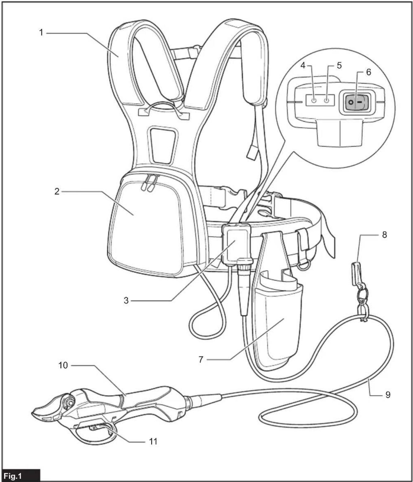

natural_image
Illustration of a person holding two safety harnesses with arrows indicating movement or force (no text or symbols)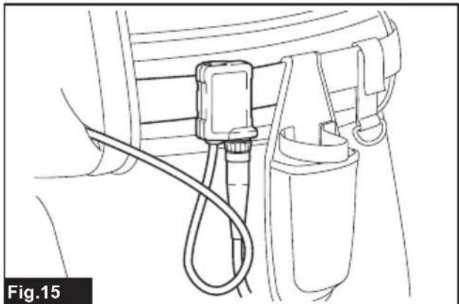
natural_image
Line drawing of a mechanical device with a cable and connector (no text or symbols)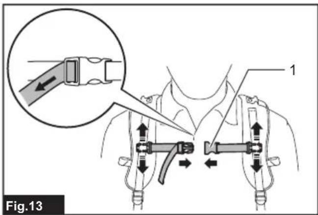
natural_image
Diagram of a rope knot being tied with a hook, showing rope routing and angle measurement (no text or symbols)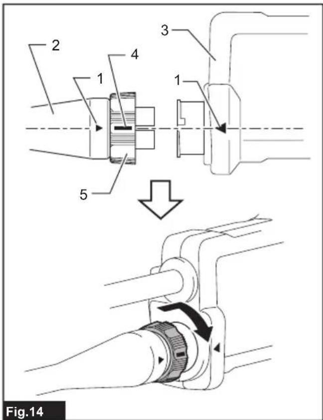

natural_image
Line drawing of a person wearing a high-visibility vest with attached harnesses and straps (no text or symbols)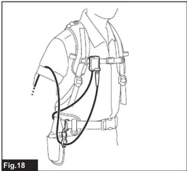
natural_image
Line drawing of a person wearing a full-body medical harness with attached straps and straps (no text or symbols)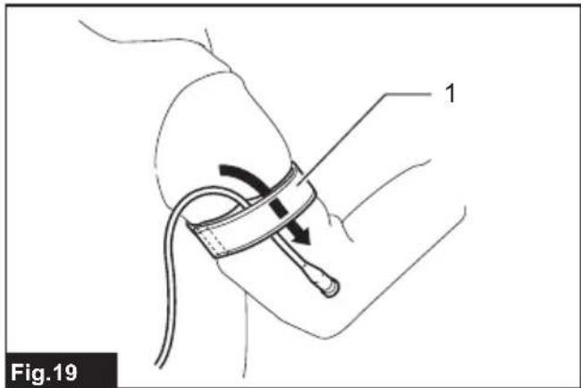
natural_image
Line drawing of a mechanical component with a rod and circular features (no text or symbols)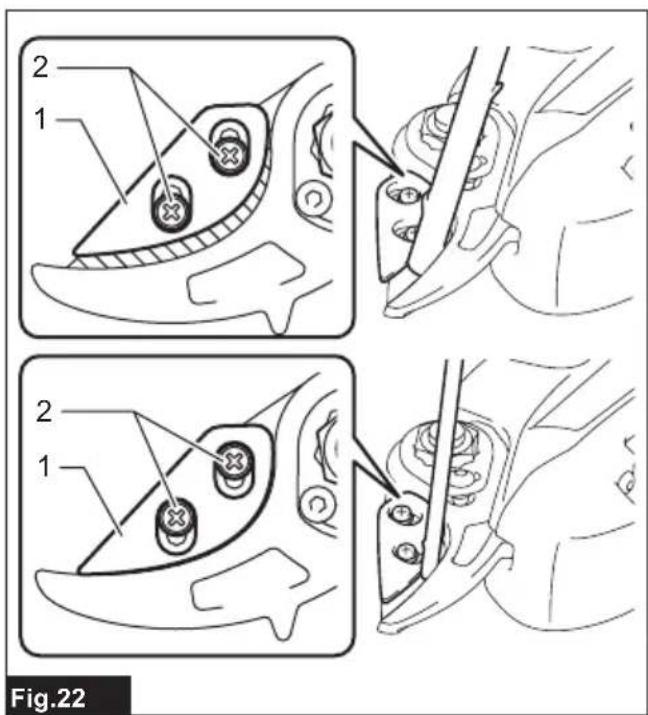

natural_image
Illustration of two hands using pliers to cut a tool, no text or symbols present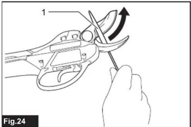
natural_image
Illustration of a hand using a tool to adjust or install a mechanical component, with an arrow indicating rotation (no text or symbols present)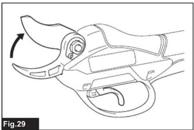
natural_image
Line drawing of a mechanical tool with an arrow indicating rotational motion (no text or symbols)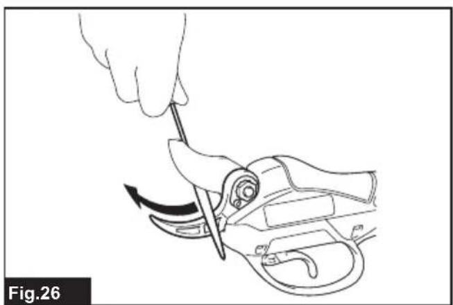
natural_image
Line drawing of a hand using a tool to adjust or install a mechanical component, no text or symbols present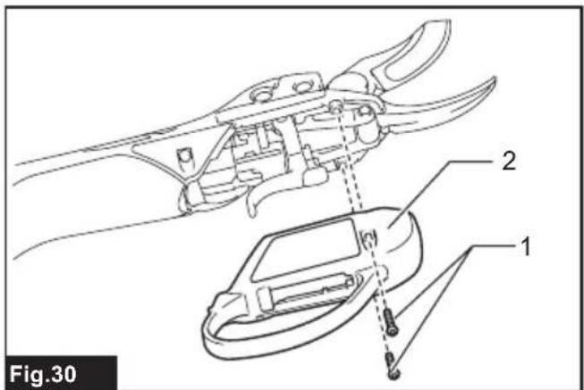

natural_image
Line drawing of a pliers being inserted into a tool, showing blade deformation (no text or symbols)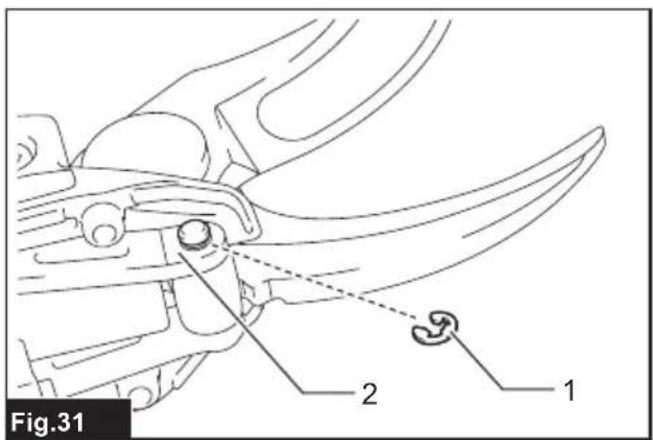

natural_image
Technical line drawing of a mechanical tool with an attached device, showing internal components and a dashed arrow indicating motion (no text or symbols)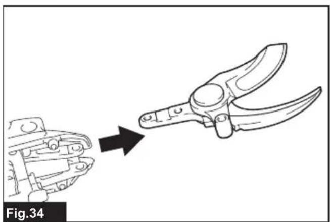
natural_image
Line drawing of a manual pliers being cut from a mechanical component, labeled Fig.34 (no text or symbols on the diagram itself)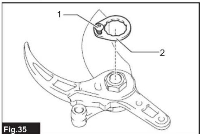
SPECIFICATIONS
| Model: DUP361 DUP362 | ||
| Max. cutting capacity 33 mm | ||
| Overall length (shears part) 305 mm | ||
| Rated voltage D.C.36 V | ||
| Net weight (shears part) 0.77 - 0.82 kg | ||
- Due to our continuing program of research and development, the specifications herein are subject to change without notice.
• Specifications may differ from country to country.
• Weight, the shears part only, according to EPTA-Procedure 01/2014
Applicable battery cartridge and charger
| Battery cartridge BL1815N / BL1820B / BL1830B / BL1840B / BL1850B / BL1860B | |
| Charger DC18RC / DC18RD / DC18RE / DC18SD / DC18SE / DC18SF /DC18SH / DC18WC |
- Some of the battery cartridges and chargers listed above may not be available depending on your region of residence.

WARNING: Only use the battery cartridges and chargers listed above. Use of any other battery cartridges and chargers may cause injury and/or fire.

WARNING: Do not use a corded power supply such as battery adapter or portable power pack with its tool. Wearing more than one harness at a time makes it difficult to operate and release the tool, and may use an injury.
Symbols
The followings show the symbols which may be used for the equipment. Be sure that you understand their meaning before use.


Read instruction manual.
Do not expose to moisture.
Do not expose to rain.
DANGER - Keep hands away from blade.
Danger; be aware of thrown objects.
Keep bystanders away.

Ni-MH Li-ion
Only for EU countries
Due to the presence of hazardous components in the equipment, waste electrical and electronic equipment, accumulators and batteries may have a negative impact on the environment and human health. Do not dispose of electrical and electronic appliances or batteries with household waste!
In accordance with the European Directive on waste electrical and electronic equipment and on accumulators and batteries and waste accumulators and batteries, as well as their adaptation to national law, waste electrical equipment, batteries and accumulators should be stored separately and delivered to a separate collection point for municipal waste, operating in accordance with the regulations on environmental protection.
This is indicated by the symbol of the crossed-out wheeled bin placed on the equipment.
Intended use
The tool is intended for pruning twigs or branches.
Noise
The typical A-weighted noise level determined according to EN62841-4-5:
Model DUP361
Sound pressure level ( L_pA ): 70 dB(A) or less
Uncertainty (K) : 3.1 dB (A)
Model DUP362
Sound pressure level ( L_pA ): 70 dB(A) or less
Uncertainty (K) : 3 dB(A)
The noise level under working may exceed 80 dB (A).
NOTE: The declared noise emission value(s) has been measured in accordance with a standard test method and may be used for comparing one tool with another.
NOTE: The declared noise emission value(s) can also be used in a preliminary assessment of exposure.
WARNING: Wear ear protection.
⚠ WARNING: The noise emission during actual use of the power tool can differ from the declared total value(s) depending on the ways in which the tool is used.
⚠ WARNING: Be sure to identify safety measures to protect the operator that are based on an estimation of exposure in the actual conditions of use (taking account of all parts of the operating cycle such as the times when the tool is switched off and when it is running idle in addition to the trigger time).
Vibration
The continuous vibration total value (tri-axial vector sum) determined according to EN62841-4-5:
Model DUP361
Vibration emission ( a_h ): 2.5 m/s ^2 or less Uncertainty (K): 1.5 m/s ^2
Model DUP362
Vibration emission ( a_h ): 2.5 m/s ^2 or less Uncertainty (K): 1.5 m/s ^2
NOTE: The declared vibration total value(s) has been measured in accordance with a standard test method and may be used for comparing one tool with another.
NOTE: The declared vibration total value(s) can also be used in a preliminary assessment of exposure.
⚠ WARNING: The vibration emission during actual use of the power tool can differ from the declared total value(s) depending on the ways in which the tool is used.
⚠ WARNING: Be sure to identify safety measures to protect the operator that are based on an estimation of exposure in the actual conditions of use (taking account of all parts of the operating cycle such as the times when the tool is switched off and when it is running idle in addition to the trigger time).
Declarations of Conformity
For European countries only
The Declarations of conformity are included in Annex A to this instruction manual.
SAFETY WARNINGS
General power tool safety warnings
⚠ WARNING Read all safety warnings, instructions, illustrations and specifications provided with this power tool. Failure to follow all instructions listed below may result in electric shock, fire and/or serious injury.
Save all warnings and instructions for future reference.
The term "power tool" in the warnings refers to your mains-operated (corded) power tool or battery-operated (cordless) power tool.
Pruning shears safety warnings
- Do not use the pruning shear in bad weather conditions, especially when there is a risk of lightning. This decreases the risk of being struck by lightning.
- Keep all power cords and cables away from cutting area. Power cords or cables may be hidden and can be accidentally cut by the blade.
- Wear ear protection. Adequate protective equipment will reduce the risk of hearing loss.
- Hold the pruning shear by insulated gripping surfaces only, because the blade may contact hidden wiring. Blades contacting a "live" wire may make exposed metal parts of the pruning shear "live" and could give the operator an electric shock.
- Keep all parts of the body away from the blade. Do not remove cut material or hold material to be cut when blades are moving. Blades continue to move after the switch is turned off. A moment of inattention while operating the pruning shear may result in serious personal injury.
- When clearing jammed material or servicing the pruning shear, make sure the power switch is off and the battery pack is removed or disconnected. Unexpected actuation of the pruning shear while clearing jammed material or servicing may result in serious personal injury.
- Carry the pruning shear by the handle with the blade stopped and taking care not to operate the power switch. Proper carrying of the pruning shear will decrease the risk of inadvertent starting and resultant personal injury from the blades.
- When transporting or storing the pruning shear, make sure the blades are in the closed position. Proper handling of the pruning shear will decrease the risk of personal injury from the blades.
Additional Safety Instructions
General instructions
-
To ensure correct operation, user has to read this instruction manual to make himself familiar with the handling of the equipment. Users insufficiently informed will risk danger to themselves as well as others due to improper handling.
-
Never allow children, persons with reduced physical, sensory or mental capabilities or lack of experience and knowledge or people unfamiliar with these instructions to use the machine, local regulations may restrict the age of the operator.
- Use the equipment with the utmost care and attention.
- Operate the equipment only if you are in good physical condition. Perform all work calmly and carefully. Use common sense and keep in mind that the operator or user is responsible for accidents or hazards occurring to other people or their property.
- Never operate the machine while people, especially children, or pets are nearby.
- The motor is to be switched off immediately in case that the equipment shows any problem or abnormal sign.
- Switch off and remove the battery cartridge when resting and when leaving the equipment unattended, and place it in a safe location to prevent danger to others or damage to the equipment.
- Avoid using the machine in bad weather conditions especially when there is a risk of lightning.
Personal protective equipment
- Wear eye protection and stout shoes at all times while operating the machine.
- Always wear substantial footwear and long trousers while operating the machine.
Starting up the equipment
- Make sure that there are no children or other people nearby, also pay attention to any animals in the working vicinity. Otherwise stop using the equipment.
- Before use always check that the equipment is safe for operation. Check the security of the cutting tool and the guard and the switch trigger/lever for easy and proper action. Check for clean and dry handles and test the function of the start/stop.
- Check damaged parts before further use of the equipment. A guard or other part that is damaged should be carefully checked to determine that it will operate properly and perform its intended function. Check for alignment of moving parts, binding of moving parts, breakage of parts, mounting, and any other condition that may affect its operation. A guard or other part that is damaged should be properly repaired or replaced by our authorized service center unless indicated elsewhere in this manual.
- Switch on the motor only when the hands and feet are away from the cutting tool.
- Before starting make sure that the cutting tool has no contact with any objects.
- Check the branches for foreign objects, such as wire fences or hidden wiring before operating the tool.
Method of operation
- Only use the equipment in good light and
visibility. During the winter season beware of slippery or wet areas, ice and snow (risk of slipping). Always ensure a safe footing on slopes and be sure to walk and never run.
- Take care against injury to feet and hands from the cutting tool.
- Never stand on a ladder and run the equipment.
- Never climb up into trees to perform cutting operation with the equipment.
- Never work on unstable surfaces.
- Remove sand, stones, nails etc. found within the working range. Foreign particles may damage the cutting tool and can cause dangerous kick-backs.
- Should the cutting tool hit stones or other hard objects, immediately switch off the motor and inspect the cutting tool.
- Inspect the cutting tool at short regular intervals for damage (detection of hairline cracks by means of tapping-noise test).
- Before commencing cutting, the cutting tool must have reached full working speed.
- The cutting tool has to be equipped with the appropriate guard. Never run the equipment with damaged guards or without guards in place!
- All protective installations and guards supplied with the equipment must be used during operation.
- Always remove the battery cartridge from the equipment:
— whenever leaving the equipment unattended;
— before clearing a blockage;
— before checking, cleaning or working on the equipment;
— after striking a foreign object;
— whenever the equipment starts vibrating abnormally.
- Always ensure that the ventilation openings are kept clear of debris.
- Cutting means continues to run after the motor is switched off.
- If the blades stop moving due to the stuck of foreign objects between the blades during operation, switch off the tool and remove the battery cartridge, and then remove the foreign objects using tools such as pliers. Removing the foreign objects by hand may cause an injury for the reason that the blades may move in reaction to removing the foreign objects.
Cutting Tools
Employ only the correct cutting tool for the job in hand.
Maintenance instructions
- The condition of the equipment, in particular of the cutting tool of the protective devices must be checked before commencing work.
-
Turn off the motor and remove the battery cartridge before carrying out maintenance, replacing cutting tools or cleaning the equipment or cutting tool.
-
When not in use, store the equipment indoors in dry and high or locked-up place - out of the reach of children. Clean and maintain before storage.
SAVE THESE INSTRUCTIONS.
⚠ WARNING: DO NOT let comfort or familiarity with product (gained from repeated use) replace strict adherence to safety rules for the subject product. MISUSE or failure to follow the safety rules stated in this instruction manual may cause serious personal injury.
Important safety instructions for battery cartridge
- Before using battery cartridge, read all instructions and cautionary markings on (1) battery charger, (2) battery, and (3) product using battery.
- Do not disassemble or tamper with the battery cartridge. It may result in a fire, excessive heat, or explosion.
- If operating time has become excessively shorter, stop operating immediately. It may result in a risk of overheating, possible burns and even an explosion.
-
If electrolyte gets into your eyes, rinse them out with clear water and seek medical attention right away. It may result in loss of your eyesight.
-
Do not short the battery cartridge:
(1) Do not touch the terminals with any conductive material.
(2) Avoid storing battery cartridge in a container with other metal objects such as nails, coins, etc.
(3) Do not expose battery cartridge to water or rain.
A battery short can cause a large current flow, overheating, possible burns and even a breakdown.
-
Do not store and use the tool and battery cartridge in locations where the temperature may reach or exceed 50 °C (122 °F).
-
Do not incinerate the battery cartridge even if it is severely damaged or is completely worn out. The battery cartridge can explode in a fire.
-
Do not nail, cut, crush, throw, drop the battery cartridge, or hit against a hard object to the battery cartridge. Such conduct may result in a fire, excessive heat, or explosion.
-
Do not use a damaged battery.
-
The contained lithium-ion batteries are subject to the Dangerous Goods Legislation requirements.
For commercial transports e.g. by third parties, forwarding agents, special requirement on packaging and labeling must be observed.
For preparation of the item being shipped, consulting an expert for hazardous material is required. Please also observe possibly more detailed national regulations.
Tape or mask off open contacts and pack up the
battery in such a manner that it cannot move around in the packaging.
-
When disposing the battery cartridge, remove it from the tool and dispose of it in a safe place. Follow your local regulations relating to disposal of battery.
-
Use the batteries only with the products specified by Makita. Installing the batteries to non-compliant products may result in a fire, excessive heat, explosion, or leak of electrolyte.
-
If the tool is not used for a long period of time, the battery must be removed from the tool.
-
During and after use, the battery cartridge may take on heat which can cause burns or low temperature burns. Pay attention to the handling of hot battery cartridges.
-
Do not touch the terminal of the tool immediately after use as it may get hot enough to cause burns.
-
Do not allow chips, dust, or soil stuck into the terminals, holes, and grooves of the battery cartridge. It may cause heating, catching fire, burst and malfunction of the tool or battery cartridge, resulting in burns or personal injury.
-
Unless the tool supports the use near high-voltage electrical power lines, do not use the battery cartridge near high-voltage electrical power lines. It may result in a malfunction or breakdown of the tool or battery cartridge.
-
Keep the battery away from children.
SAVE THESE INSTRUCTIONS.
CAUTION: Only use genuine Makita batteries. Use of non-genuine Makita batteries, or batteries that have been altered, may result in the battery bursting causing fires, personal injury and damage. It will also void the Makita warranty for the Makita tool and charger.
NOTICE: Makita is not responsible for any accidents resulting from the use of non-genuine Makita batteries or batteries that have been modified. Genuine Makita batteries have been rigorously evaluated for compatibility with Makita tools and chargers, in line with applicable legislation and safety standards.
Tips for maintaining maximum battery life
-
Charge the battery cartridge before completely discharged. Always stop tool operation and charge the battery cartridge when you notice less tool power.
-
Never recharge a fully charged battery cartridge. Overcharging shortens the battery service life.
-
Charge the battery cartridge with room temperature at 10 °C - 40 °C ( 50 °F - 104 °F ). Let a hot battery cartridge cool down before charging it.
-
When not using the battery cartridge, remove it from the tool or the charger.
-
Charge the battery cartridge if you do not use it for a long period (more than six months).
PARTS DESCRIPTION
▶ Fig.1
| 1 | Harness * | 2 | Back pack | 3 | Switch box | 4 | Pilot lamp (red) |
| 5 | Pilot lamp (green) | 6 | I/O switch | 7 | Holster | 8 | Cord holder |
| 9 | Connection cord | 10 | Shears | 11 | Switch trigger | - | - |
* The shape may differ depending on the tool variation.
FUNCTIONAL DESCRIPTION
⚠️CAUTION: Always be sure that the tool is switched off and the battery cartridge is removed before adjusting or checking function on the tool.
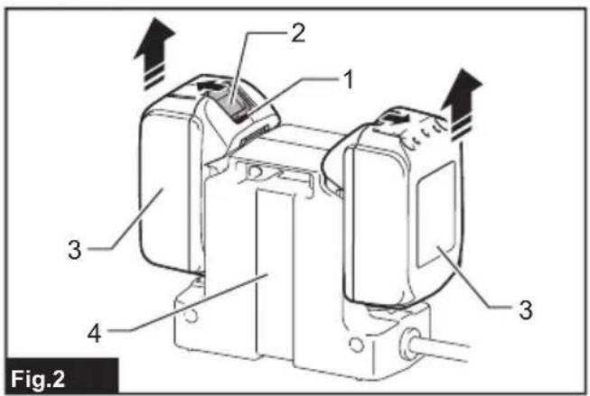
Removing or installing battery cartridge
⚠️CAUTION: Always switch off the tool before installing or removing of the battery cartridge.
⚠️CAUTION: Hold the tool and the battery cartridge firmly when installing or removing battery cartridge. Failure to hold the tool and the battery cartridge firmly may cause them to slip off your hands and result in damage to the tool and battery cartridge and a personal injury.
▶ Fig.2: 1. Red indicator 2. Button 3. Battery cartridge 4. Battery holder
To remove the battery cartridge, slide it from the tool while sliding the button on the front of the cartridge.
To install the battery cartridge, align the tongue on the battery cartridge with the groove in the housing and slip it into place. Insert it all the way until it locks in place with a little click. If you can see the red indicator on the upper side of the button, it is not locked completely.
⚠️CAUTION: Always install the battery cartridge fully until the red indicator cannot be seen. If not, it may accidentally fall out of the tool, causing injury to you or someone around you.
⚠️CAUTION: Do not install the battery cartridge forcibly. If the cartridge does not slide in easily, it is not being inserted correctly.
NOTE: The tool does not work with only one battery cartridge.
Tool / battery protection system
The tool is equipped with a tool/battery protection system. This system automatically cuts off power to the motor to extend tool and battery life. The tool will automatically stop during operation if the tool or battery is placed under one of the following conditions. In some conditions, the lamps on the switch box lights up.
Overload protection
When the tool is operated in a manner that causes it to draw an abnormally high current, the tool automatically stops without any indication. In this situation, turn the tool off and stop the application that caused the tool to become overloaded. Then turn the tool on to restart.
Overheat protection
When the tool is overheated, the tool stops automatically, and the green lamp on the switch box blinks. In this situation, let the tool cool down before turning the tool on again.
Overdischarge protection
When the battery capacity becomes low, the tool stops automatically. And the red lamp on the switch box lights up or blinks. If the product does not operate even when the switches are operated, remove the batteries from the battery holder and charge the batteries.
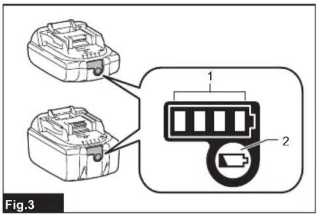
Indicating the remaining battery capacity
Only for battery cartridges with the indicator
Press the check button on the battery cartridge to indicate the remaining battery capacity. The indicator lamps light up for a few seconds.
▶ Fig.3: 1. Indicator lamps 2. Check button
| Indicator lamps | Remaining capacity | ||
| Lighted | Off | Blinking | |
| [mmol] | 75% to 100% | ||
| [mmol] | 50% to 75% | ||
| [mmol] | 25% to 50% | ||
| [mmol] | 0% to 25% | ||
| [mmol] | Charge the battery. | ||
 | The battery may have malfunctioned. | ||
NOTE: Depending on the conditions of use and the ambient temperature, the indication may differ slightly from the actual capacity.
NOTE: The first (far left) indicator lamp will blink when the battery protection system works.
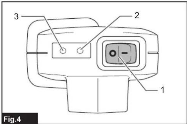
Switch action
⚠️CAUTION: Before connecting the battery to the shears, always check to see that the switch trigger actuates properly and returns to the “OFF” position when released.
⚠CAUTION: When not operating the tool, always make sure that the I/O switch is on the "O" side.
CAUTION: Do not press the I/O switch to the "I" (on) position while pulling the switch trigger. The blade closes slightly and it may cause personal injury.
To turn on the tool, perform as follows:
- Connect the switch box, connection cord, and shears. (Refer to "Installing the connection cord".)
- Hold the shears firmly, and press the I/O switch to the "I" (on) position. The green pilot lamp lights up.
▶ Fig.4: 1. I/O switch 2. Pilot lamp (green) 3. Pilot lamp (red)
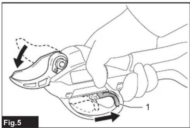
- The shear blades are locked-mode when the I/O switch is on. To release the lock, pull the switch trigger two times. The upper shear blade opens automatically.
- To close the shear blade, pull the switch trigger.
▶ Fig.5: 1. Switch trigger
Auto locked-mode and shut-off mode shift
For safety reasons, the tool shifts into locked-mode or shut-off mode automatically if the tool is left untouched for a certain period of time.
After 5 minutes: The tool shifts into locked-mode. Pull the switch trigger two times to release the lock.
After 15 minutes: The tool is shift into shut-off mode, and the green pilot lamp turns off. Press the I/O switch to the "O" (off) position once, and press the I/O switch to the "I" (on) position again, then pull the switch trigger two times to release the lock.
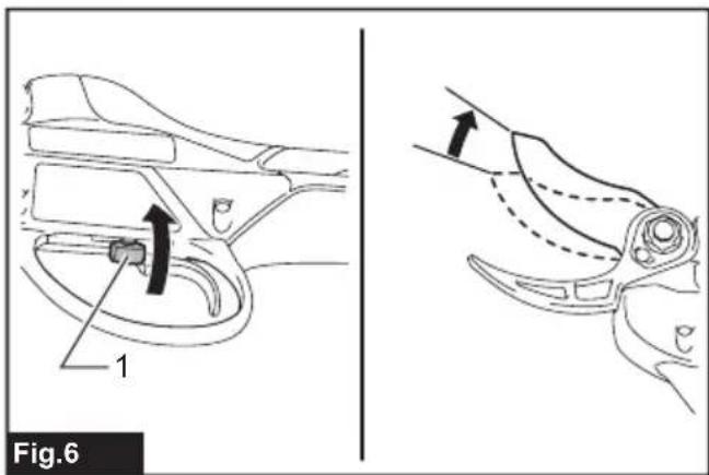
Opening angle selector lever
▶ Fig.6: 1. Opening angle selector lever
By tilting the opening angle selector lever to the left side, you can open the upper shear blade wider.
To limit the upper shear blade opening angle, first pull the switch trigger fully, and then return the opening angle selector lever to straight position.
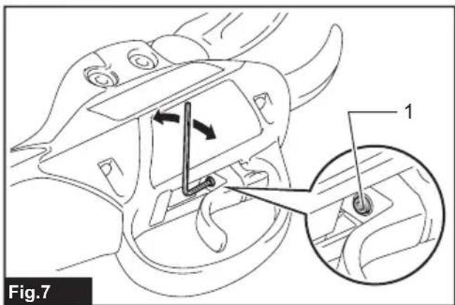
Cutting depth adjustment
⚠️CAUTION: Do not let your hands or part of body close to the shear blades. Otherwise personal injury may result.
After sharpening or replacing the shear blade, adjust cutting depth if necessary.
Turn on the tool, and pull the switch trigger two times to open the shear blades, and then press the I/O switch to the "O" (off) position.
To deepen the cutting depth, turn the cutting depth adjusting screw clockwise with the hex wrench. And to make the cutting depth shallower, turn the cutting depth adjusting screw counterclockwise.
▶ Fig.7: 1. Cutting depth adjusting screw
NOTE: Check the cutting depth after adjustment. If the cutting depth is too shallow, the branch may not cut fully.
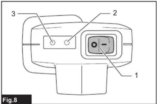
Pilot lamps on the switch box
▶ Fig.8: 1. I/O switch 2. Pilot lamp (green) 3. Pilot lamp (red)
The green and red lamps indicate as follows: (On: Off: Blinking: )
- Green lamp lights up: the tool is turned on.
| Green Red | |
- Green lamp and red lamp light up: if you insert the battery to the battery holder when I/O switch is "I" (on) position, both of the lamps light up and the blade does not move though you pull the switch trigger. In this situation, press the I/O switch to the "O" (off) position once, and press the I/O switch to the "I" (on) position again.
| Green Red | |
| ● | ● |
- Green lamp blinks: the tool is overheated. Let the tool cool down before turning the tool on again.
| Green Red | ||
- Green lamp lights up and red lamp blinks or lights up: battery is low or almost flat. Charge the batteries. When either of the battery becomes low, the red lamp blinks even one of the batteries is full.
| Green Red | ||
- Green lamp and red lamp blink alternately: the tool detects breaking of wire. Check the connection cord for loose connection with the switch box and the shears. If the lamps still blink alternately, stop using the tool immediately, disconnect the connection cord, remove the battery, and ask your local authorized service center for repair.
| ⚠️ | Lamps blink alternately |
| ○ ● ↔ ● ○ |
ASSEMBLY
⚠️CAUTION: Always be sure that the tool is switched off and the battery cartridge is removed before carrying out any work on the tool.
Installing the battery holder into the backpack
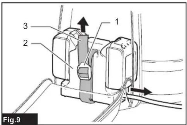
▶ Fig.9: 1. Clamp 2. Battery holder 3. Strap
- Pass the switch box through the opening (either right or left) of the back pack.
- Pass the clamp through the square hole of the battery holder, and secure the battery holder with the strap. Make sure that the battery holder sits in the backpack firmly.
Installing the holster
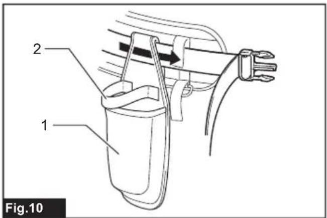
▶ Fig.10: 1. Holster 2. Strap
Pass the belt of the lower buckle through the opening of the holster.
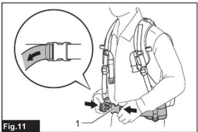
Adjusting the harness
Adjust the harness as follows:
- Close and lock the lower buckle, and adjust its belt length.
▶ Fig.11: 1. Lower buckle
- Adjust the shoulder strap length.
▶ Fig.12
- Adjust the position of the upper buckle. Close and lock the upper buckle and adjust its belt length.
▶ Fig.13: 1. Upper buckle
⚠️CAUTION: In case of emergency, quickly open the lower buckle and upper buckle, loosen shoulder straps, and set down the backpack.
Installing the connection cord
⚠️CAUTION: Always make sure that the switch box's I/O switch is on the "O" side before attaching the connection cord.
⚠️CAUTION: Do not operate the tool if the connection cord is damaged.
NOTICE: Do not abuse the connection cord. Do not carry the tool by pulling the connection cord. Keep the connection cord away from heat, oil, or sharp edges. Otherwise the connection cord may be damaged.
Attach the connection cord with the switch box and the shears as follows:
- First, align the triangular marks of the male plug of the connection cord with the triangular mark of the female connector of the switch box. Push in the plug of the connection cord to the connector of the switch box. Then, align the marking on the coupling with the triangular marks, and push in and turn the coupling to tighten.
▶ Fig.14: 1. Triangular mark 2. Connection cord 3. Switch box 4. Marking on coupling 5. Coupling
NOTICE: Turn the coupling and align the marking on the coupling with the triangular marks first when disconnecting the connection cable.
- Hang the switch box on the waist belt or upper belt.
▶ Fig.15
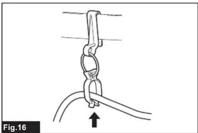
- Push the connection cord into the loop of the cord holder.
▶ Fig.16
Hang the cord holder on either the upper belt or the waist belt on which the switch box is not hung.
The cord holder prevents the connection cord from dangling around your body, and also the cord holder can prevent the connection cord from being cut by mistake.
▶ Fig.17
▶ Fig.18
NOTICE: Do not hang anything other than the connection code on the cord holder. Otherwise the code holder may be broken.
NOTICE: Do not force the cord holder opening. Otherwise it may result in deformation or breakage of the code holder.
- Put the arm band on your arm. And slip the connection cord through the arm band.
▶ Fig.19: 1. Arm band
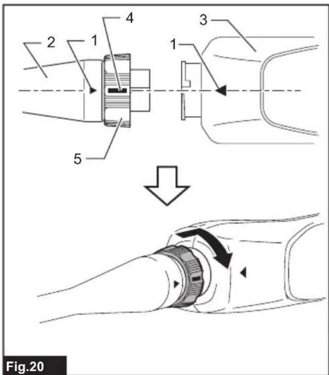
- First, align the triangular marks of the female socket of the connection cord with the triangular mark of the male connector of the shears. Push in the socket of the connection cord to the connector of the shears. Then, align the marking on the coupling with the triangular marks, and push in and turn the coupling to tighten.
▶ Fig.20: 1. Triangular mark 2. Connection cord 3. Shears 4. Marking on coupling 5. Coupling
NOTICE: Turn the coupling and align the marking on the coupling with the triangular marks first when disconnecting the connection cable.
Putting shears in the holster
Keep pulling the switch trigger to close the shear blades, and press the I/O switch to "O" side to turn off the tool. Then put the shears into the holster and hold the shears with the strap of the holster.
OPERATION
⚠️CAUTION: Always hold the tool firmly. And keep firm footing.
⚠️CAUTION: Do not put any of your body parts near the shear blades during operation.
⚠CAUTION: Before use, inspect if the shear blades, blade bolts or other parts are not worn or damaged. Replace worn or damaged parts for safe operation.
NOTICE: If the blade is stuck in a branch during operation, do not twist the blade. In that situation, turn off the tool and pull the blades straight out slowly from the branch. Otherwise the blade may be damaged.
NOTICE: In case you cut too thick branch or something too hard, the overload protection works and the tool stops. In that situation, if the upper shear blade is opened too wide and the switch trigger is pulled fully, the upper blade closes slightly when you press the I/O switch to "I" (on) position for restarting the tool.
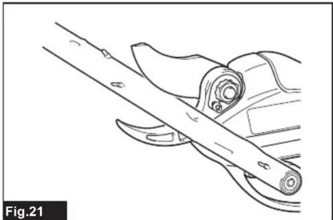
Pruning operation
▶ Fig.21
Cut branches one by one. The maximum thickness of branches which can be cut with these shears is about 33mm. Maintain your proper footing and balance at all times.
After use
Close the shear blades, press the I/O switch to the "O" (off) position, and disconnect the connection cord from the shears and the switch box, and remove the batteries from battery holder.
Store the shears in dry, high or locked-up place – out of reach of children.
NOTICE: Remove the battery when not using the shears. Otherwise the battery capacity is reduced during course of time.
Catcher
Optional accessory
The catcher is useful, when picking flowers. It temporarily holds picked flower after cutting.
If the clearance between the catcher and lower blade is not appropriate for your application, adjust the clearance by loosening the screws.
▶ Fig.22: 1. Catcher 2. Screw
MAINTENANCE
CAUTION: Always be sure that the tool is switched off and the battery cartridge is removed before attempting to perform inspection or maintenance.
CAUTION: Wear safety gloves when handling the shear blade. Otherwise it may result in personal injury.
NOTICE: Never use gasoline, benzine, thinner, alcohol or the like. Discoloration, deformation or cracks may result.
Blade maintenance
NOTICE: Failure to perform blade maintenance may cause excessive blade friction and shorten the operating time per battery charge.
Before and after operation, check the shear blades carefully.
After operation, clean off the blades with a stiff brush. Then wipe the blades with a cloth. And apply Makita genuine machine oil onto the blade edge and movable part.
▶ Fig.23
Sharpening blades
Upper shear blade
- Apply the flat surface of the diamond file to the blade edge.
Push the diamond file towards the tip of the blade to sharpen along the entire blade edge.
Maintain the same flat contact with the file consistently along the entire blade edge.
▶ Fig.24: 1. Diamond file
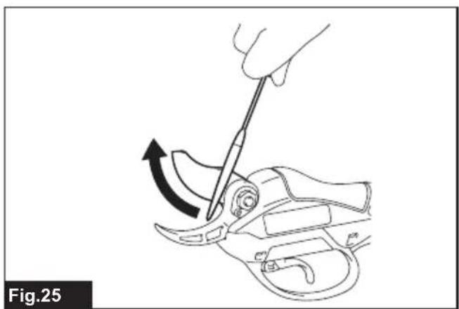
- Apply the flat surface of the diamond file lightly to the opposite side of the blade.
Move the diamond file towards the tip of the blade lightly to remove burrs.
▶ Fig.25
NOTICE: Do not sharpen this side too much. File lightly only for removing burrs. Otherwise the blade clearance may become too much or the blade life may be shortened.
Lower shear blade
- Apply the round surface of the diamond file to the blade edge.
Push the diamond file towards the tip of the blade to sharpen along the entire blade edge.
▶ Fig.26
- Apply the flat surface of the diamond file lightly to the opposite side of the blade.
Move the diamond file towards the tip of the blade lightly to remove burrs.
▶ Fig.27
NOTICE: Do not sharpen this side too much. File lightly only for removing burrs. Otherwise the blade clearance may become too much or the blade life may be shortened.
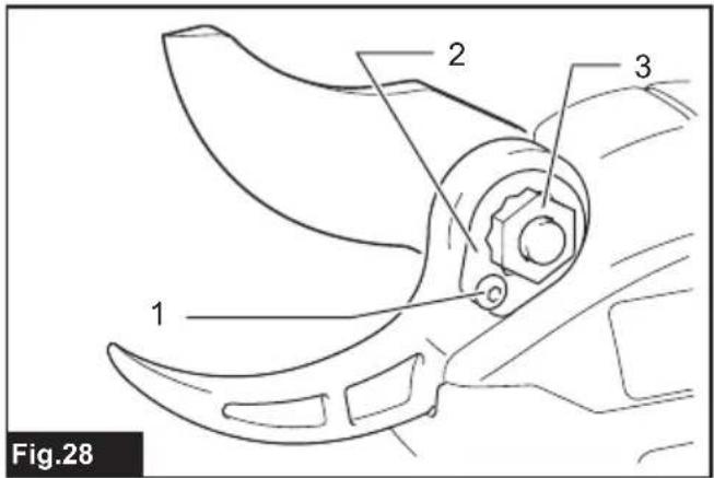
Adjustment for blade clearance
▶ Fig.28: 1. Plate fixing bolt 2. Lock plate 3. Blades tightening nut
From time to time, adjust the clearance of the shear blades as follows:
- Switch on the tool, and pull the switch trigger to open the shear blades.
- With shear blades open, switch off the tool. And disconnect the connection cord from the tool.
- Loosen the plate fixing bolt. And then remove the lock plate.
- Adjust the tightness of the blades tightening nut by hand (fastening torque for the blade tightening nut: approximately 0.5 N·m).
- Install the lock plate and plate fixing bolt again.
- Check the tightness of the blade whether the blades never rattle but upper blade can be opened or closed about 3mm by hand. If the blades are too tight or loose, adjust the clearance again.
NOTICE: Pay attention to the clearance of the blades. Too loose clearance may result in dull cut, and too tight blade clearance may result in overload for the motor and short running time of the tool.
Removing or installing shear blades
To remove the shear blades, perform following steps:
- Tilt the opening angle selector lever to the left side first to open the blades fully.
- Switch on the tool, and pull the switch trigger to open the shear blades.
- With shear blades open, switch off the tool. And disconnect the connection cord from the tool.
▶ Fig.29
- Remove two bolts near the switch trigger with the hex wrench.
Remove the trigger guard by separating the tongue on the trigger guard from the groove of the housing.
▶ Fig.30: 1. Bolts 2. Trigger guard
- Remove the E-ring on the link arm with a slotted screwdriver or alike.
▶ Fig.31: 1. E-ring 2. Link arm
NOTICE: The E-ring is expendable part. Do not re-use the E-ring when reassembling.
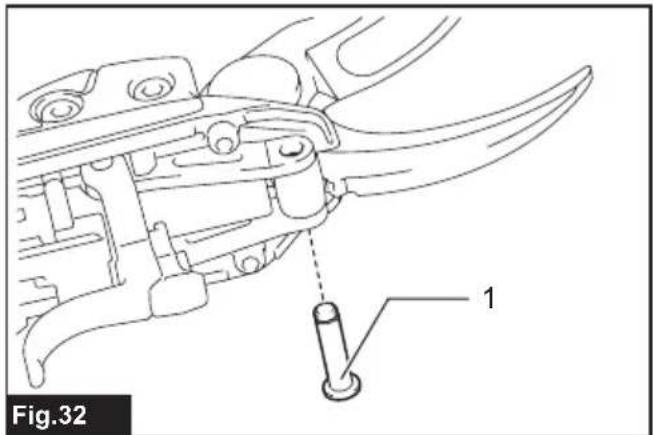
- Carefully remove the pin.
▶ Fig.32: 1. Pin
- Remove two bolts from the side of the housing.
▶ Fig.33: 1. Bolts
- Carefully remove the upper and lower shears from the housing.
▶ Fig.34
- To separate the upper blade and the lower blade, first loosen the plate fixing bolt.
Then remove the lock plate.
▶ Fig.35: 1. Plate fixing bolt 2. Lock plate
NOTE: When replacing the blades for hard branch with ones for thin branch, or vise versa, replace the plate fixing bolt as well.
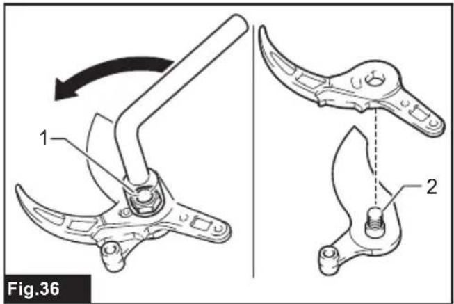
- Loosen and remove the blades tightening nut.
▶ Fig.36: 1. Blade tightening nut 2. Blade tightening bolt
NOTE: When replacing the blades for hard branch with ones for thin branch, or vise versa, replace the blade tightening bolt as well.
To install the shear blades, perform the procedures above in reverse. Make sure all the bolts are securely tightened.
After installing the blade, always adjust the blade clearance. (Refer to "Adjustment for blade clearance".)
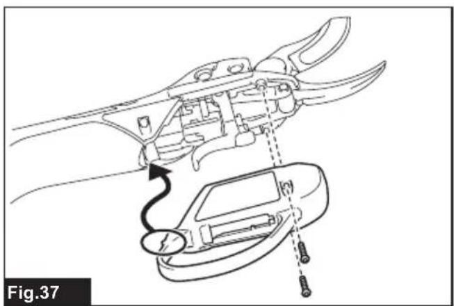
To install the shear blades, perform the procedures above in reverse. When installing the shear blades, pay attention to the following points:
- Apply machine oil or grease on to the blade tightening bolt and between the blades.
- If you can not place the plate fixing bolt properly, first, remove the O-ring and the plate fixing bolt from the lock plate. And then overturn the lock plate, and return the O-ring and the plate fixing bolt.
- When installing the trigger guard, align the tongue of the trigger guard with the groove of the housing.
• Make sure all the bolts are securely tightened. - After installing the blade, always adjust blade clearance. (Refer to "Adjustment for blade clearance".)
• After installing the blade, always adjust cutting depth. (Refer to "Cutting depth adjustment".)
▶ Fig.37
Trouble shooting
Before making a request for repairs, check for trouble by yourself. If any abnormality is found, control your tool according to the description of this manual. If the remedy mentioned below cannot solve the problem, ask your local authorized service center for repair. Never tamper or dismount any part contrary to the description.
| State of abnormality | Probable cause (malfunction) | Remedy |
| The shear blade does not move even after pulling the switch trigger. | The battery is low. | Charge the battery. |
| I/O switch is "Off" position. | Press the I/O switch to "I" position. | |
| The shears are locked. | Unlock the shears by performing the steps in "Switch action". | |
| Connection cord is loose. | Check the connecting points of the switch box and shears of connection cord. | |
| I/O switch is "on" position when inserting the battery cartridge. | Press the I/O switch to the "O" (off) position once, and press the I/O switch to the "I" (on) position again. | |
| Switch trigger defect. | Stop using the tool immediately, and ask your local authorized service center for repair. | |
| The shear blades are stuck on the branch. | The branch is too thick. | Release the switch trigger. Press the I/O switch to "O" position. Then pull the blades straight out slowly from the branch. |
| The switch trigger is locked and can not be pulled. | Shear blades are opened forcibly. | Switch off and on with the I/O switch. (The upper shear blade closes slightly when switching on.) |
| The cut is not smooth. | The shear blades are dull. | Sharpen the shear blades, or adjust blade clearance. |
| The shear blades are worn out. | Replace the shear blades. |
To maintain product SAFETY and RELIABILITY, repairs, any other maintenance or adjustment should be performed by Makita Authorized or Factory Service Centers, always using Makita replacement parts.
OPTIONAL ACCESSORIES
⚠️CAUTION: These accessories or attachments are recommended for use with your Makita tool specified in this manual. The use of any other accessories or attachments might present a risk of injury to persons. Only use accessory or attachment for its stated purpose.
If you need any assistance for more details regarding these accessories, ask your local Makita Service Center.
• Upper shear blade
• Upper shear blade (for hard branch)
• Upper shear blade (for thin branch)
• Lower shear blade
• Lower shear blade (for hard branch)
• Lower shear blade (for thin branch)
• Plate fixing bolt (for thin branch)
- Blade tightening bolt (for thin branch)
- Catcher (holding picked flower after cutting.)
- Diamond file
- Arm band
- Holster
- Cord holder
• Makita genuine battery and charger
NOTE: Some items in the list may be included in the tool package as standard accessories. They may differ from country to country.
SPÉCIFICATIONS
▶ Fig.5: 1. Gâchette
▶ Abb.24: 1. Diamantfeile
▶ Abb.31: 1. E-Ring 2. Gelenkarm
⚠ WAARSCHUWING: Draag gehoorbescherming.
VEILIGHEIDSWAAR- SCHUWINGEN
▶ Fig.6: 1. Openingshoek-keuzehendel
▶ Fig.22: 1. Klembek 2. Schroef
ONDERHOUD
OPTIONELE ACCESSOIRES


- Applicable battery cartridge and charger
- Symbols
- Intended use
- Noise
- Model DUP362
- WARNING: Wear ear protection.
- Vibration
- Model DUP361
- Declarations of Conformity
- For European countries only
- SAFETY WARNINGS
- General power tool safety warnings
- Save all warnings and instructions for future reference.
- Pruning shears safety warnings
- Additional Safety Instructions
- General instructions
- Personal protective equipment
- Starting up the equipment
- Method of operation
- Cutting Tools
- Maintenance instructions
- SAVE THESE INSTRUCTIONS.
- Important safety instructions for battery cartridge
- Tips for maintaining maximum battery life
- PARTS DESCRIPTION
- FUNCTIONAL DESCRIPTION
- Removing or installing battery cartridge
- Tool / battery protection system
- Overload protection
- Overheat protection
- Overdischarge protection
- Indicating the remaining battery capacity
- Only for battery cartridges with the indicator
- Switch action
- Auto locked-mode and shut-off mode shift
- Opening angle selector lever
- Cutting depth adjustment
- Pilot lamps on the switch box
- ASSEMBLY
- Installing the battery holder into the backpack
- Installing the holster
- Adjusting the harness
- Installing the connection cord
- Putting shears in the holster
- OPERATION
- Pruning operation
- ▶ Fig.21
- After use
- Catcher
- Optional accessory
- MAINTENANCE
- Blade maintenance
- Sharpening blades
- Upper shear blade
- Lower shear blade
- ▶ Fig.27
- Adjustment for blade clearance
- Removing or installing shear blades
- ▶ Fig.29
- ▶ Fig.34
- ▶ Fig.37
- Trouble shooting
- OPTIONAL ACCESSORIES
- ⚠ WAARSCHUWING: Draag gehoorbescherming.
- VEILIGHEIDSWAAR- SCHUWINGEN
- ONDERHOUD
- OPTIONELE ACCESSOIRES
Brand : MAKITA
Model : DUP362Z
Category : Scissors