CKT755 - Cooker Pelgrim - Free user manual and instructions
Find the device manual for free CKT755 Pelgrim in PDF.

| Features | Details |
|---|---|
| Product type | Cooker |
| Dimensions (W x D x H) | 60 x 60 x 85 cm |
| Cooking type | Gas |
| Number of burners | 4 burners |
| Oven type | Gas oven |
| Oven capacity | 60 liters |
| Oven functions | Fan oven, grill |
| Safety system | Automatic gas shut-off |
| Surface material | Enamelled steel |
| Weight | 40 kg |
| Energy consumption | Energy class A |
| Maintenance | Easy cleaning thanks to the enamelled surface |
| Included accessories | Grill rack, baking tray |
| Warranty | 2 years |
Frequently Asked Questions - CKT755 Pelgrim
User questions about CKT755 Pelgrim
0 question about this device. Answer the ones you know or ask your own.
Ask a new question about this device
Download the instructions for your Cooker in PDF format for free! Find your manual CKT755 - Pelgrim and take your electronic device back in hand. On this page are published all the documents necessary for the use of your device. CKT755 by Pelgrim.
USER MANUAL CKT755 Pelgrim
natural_image
Pure geometric diagram with concentric circles and curved lines, no text or symbols presentCKT745 CKT755 CKT770
Pelgrim
Handleiding notice d'utilisation - anleitung - manual
Inhoud
NL
Instructions for use 81-95
Installation guide 97-105
gebruikte pictogrammen - pictogrammes utilisés benutzte Piktogramme - pictograms used
natural_image
Diagram showing a component being inserted into a device, with an arrow indicating the insertion direction (no text or symbols present)natural_image
Technical line drawing of a mechanical part with an inset view showing a stepped structure (no text or symbols)text_image
Technical diagram showing a grid-patterned electrical or mechanical component with labeled dimensions and an inset cross-section view.natural_image
Diagram showing a circuit breaker connected to an electrical outlet plug, with no visible text or symbols.natural_image
Diagram showing a 3D rectangular object with a dashed box and an arrow pointing to a vertical component (no text or symbols present)natural_image
Technical line drawing of a mechanical part with a side view showing a stepped profile (no text or symbols)text_image
Technical diagram showing a stator with four wheels and a close-up of the blade structure with internal components.natural_image
Diagram showing a component being inserted into a device, with an arrow indicating the insertion direction (no text or symbols present)natural_image
Technical diagram showing a 3D mechanical part with an inset view of a stepped structure (no text or symbols)text_image
Technical diagram showing a grid-patterned electrical or mechanical component with labeled dimensions and an inset cross-section view.natural_image
Diagram showing a stovetop appliance connected to an electrical outlet plug (no text or symbols present)What you should pay attention 84-85
use
Setting 86
comfortable cooking
Optimal use of the hob 91-93
maintenance
General 94
faults
Table 95
environmental aspects
Disposal of packaging / appliance 96
installaton guide
General 97
Electrical connection 98
Built in 102-105
Pelgrim

Pelgrim
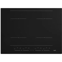
Description
CKT745
text_image
2 3 1 4 13.0 13.1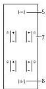
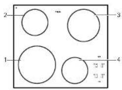
- cooking zone front left
- cooking zone rear left
- cooking zone rear right
- cooking zone front right
- childproof lock
- timer/switch-off timer
- power
- on/off button
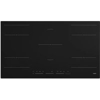
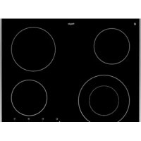
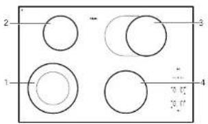
CKT755
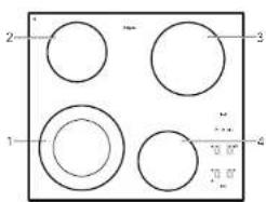
text_image
2 1 3 4 0.07 10.07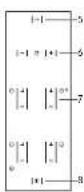
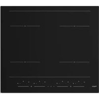
CKT770
text_image
2 1 3 4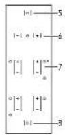
Introduction
This ceramic hob has been designed for the real lover of cooking.
The hob is equipped with 'Coollight' elements. These are very rapid heating, radiant elements with a high efficiency, which is very favourable for heating-up times. What's more, these elements also have very good heat distribution.
The ample space between the cooking zones makes cooking comfortable.
The cooking zones can be controlled accurately using soft touch controls. The position indications are intended as a reference; they enable you to select a particular setting quickly..
The appliances are equipped with one or more double circle cooking zones (except CKT745). These cooking zones have a large range of adjustment and are suitable for both small (inner cooking zone) and large pans. The CKT770 unit is equipped with a fish pan cooking zone, on which a small ordinary pan or a special fish pan can be placed.
For optimum safety the ceramic hob is equipped with a residual heat indicator, which shows which cooking zones are still hot.
This manual describes how you can make the best possible use of the ceramic hob. In addition to information about operation, you will also find background information that can assist you in using this product.
Keep this manual carefully. It serves as reference material for the service engineers. So stick the data card which is affixed to the glass plate on to the back of this manual in the box provided.
When you call the service department the stall will ask for the details on the data card. If you don't have these details, it is more difficult for us to provide accurate service
Enjoy your cooking!
What you should pay attention to
Never open the casing of the appliance
Ensure that there is adequate ventilation during use
■ Keep natural ventilation openings open.
If there is a drawer under the hob
■ Ensure that there is a sufficient gap between the hob and the contents of the drawer.
■ Do not place any flammable objects in the drawer.
Use the hob only for preparing dishes
■ The appliance is not suitable for space heating.
The cooking zones get very hot during use and also remain hot for some time after use (see also 'residual heat indication')
■ Do not allow small children in the vicinity of the hob during and soon after cooking.
Empty pans and boiling dry
■ Never leave an empty pan on a cooking zone that is switched on.
■ Avoid the pan boiling dry.
■The cooking zones are protected against overheating, but the pan may be damaged.
Always use suitable cooking utensils
■ Damage arising from the use of unsuitable pans or from boiling dry is excluded from the guarantee.
Use of fat and oil
■ Grease and oil are flammable when overheated. Stay near the cooker when preparing dishes.
Use of other equipment near the hob
■ Make sure that cables of electrical machines (such as a mixer) do not end up on hot cooking zones.
Never flambé under an extractor hood
■ The high flames can cause fire. Even if the ventilator is switched off,
Use of the cooking surface
■The glass-ceramic cooking surface is very strong but not unbreakable. A breakage may occur if a sharp object falls on it.
■ Do not use the hob as a work surface for cutting meat or vegetables, for instance.
■ Do not continue to use an appliance whose cooking surface is showing a break or cracks. Switch the appliance off immediately. Remove the plug from the socket or set the switch of the power supply cable (in the case of a fixed connection) to zero or turn off the fuse switch(es) in the meter cupboard. Phone the service department.

Pelgrim
Pelgrim
Setting
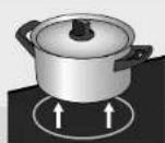
On the glass work surface the 4 cooking zones are indicated by a circle. The diameter of the base of the pan should correspond as closely as possible with the diameter of the cooking zone.
The ceramic hob is equipped with residual heat indication, (child) lock, automatic limitation of cooking time.
The CKT755 and CKT770 are also equipped with one or more double-ring cooking zones and a cooking timer.
On this page and the following ones, you can read how to use these facilities.
Switching on and off
Switching on
-
Put a pan on a cooking zone.
-
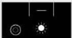
Press the on/off button,

A light above the on/off button comes on.
The hob is now in stand-by mode. You must now operate the hob within 5 seconds, otherwise the hob will switch itself off again (the light goes out).
During the cooking process the on/off button can be used as an emergency switch-off. Press the button and the appliance will switch off immediately.
Setting the power level
The cooking zones have 9 settings.
- Press the 1 button for the cooking zone concerned.
The cooking zone immediately sets itself to position 6. Or press the button for the relevant cooking zone. The cooking zone will immediately set itself to position 1. The cooking zone will now heat up. The cooking zone switches on and off automatically to provide the power you have set. At lower settings the cooking zone is off for a long time and on from time to time. At higher settings the cooking zone is on for a long time and off from time to time.
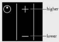
- Select a higher or lower setting by pressing the + or - key again. The display will indicate the selected setting.
The table on pages 92 and 93 shows which settings you should select.
Switching off
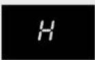
Press the - button until the cooking zone is on setting 0. After 5 seconds this will change to an H, referring to residual heat (see residual heat indication).
Pelgrim
Pelgrim
Switching on the double-ring cooking zone (CKT755 and CKT770) or fish pan cooking zone (CKT770)
Set the cooking zone to setting 9, press the - button.
The light under the - button will come on. The outer cooking zone is switched on.
The outer cooking zone follows all the settings of the inner cooking zone, even if you go to setting 0 and then select a higher setting again within 5 seconds.
You can never use the outer cooking zone on its own.
Residual-heat indicator
The indicator shows that the cooking zone is still hot, and goes out as soon as the glass top reaches a safe temperature. Residual heat is indicated by an H in the display of the appropriate cooking zone...
Residual-heat indicator
Cooking timer / switch-off timer (CKT755 en CKT770)
You can have the rear right cooking zone switched off by the cooking timer. You are then using the timer as a switch-off timer.
- Put a pan on the rear right cooking zone.
- Press the on/off button.
- Set the power level required.
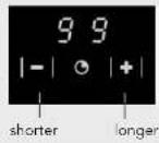
- Set the timer.
With the - and + buttons you can set a maximum cooking time of 99 minutes. If you hold the + or - button in longer, the value will increase or decrease more rapidly. If you release the button briefly and press it again, the value will change slowly again.
The selected number of minutes is indicated in the display.
A flashing dot indicates that the timer has been activated. The time will now count down and the remaining time is visible in the display.
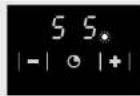
At the end of the cooking time, you hear a beep.
The zone switches off.
Switch the beep off at the end of the cooking time by pressing the clock's - button.
Press the clock's + button to set a new cooking time.
The other cooking zones cannot be switched off by the cooking timer. In that case the cooking timer merely gives an audible signal at the end of the set time (for example for use when boiling eggs).
Switch the cooking timer off by pressing the - button for a few seconds (in the '0' minute setting).
(childproof) lock
During the cooking process it is possible to fix the current settings by using the lock. Press the key button once.
The light above the button lights up. The (emergency) on/off button can still be used when the settings have been fixed with the lock function.

The lock can also be used as a child proof lock.
Locking
Switch the appliance off. Press the button with the key symbol once.
The light above the button lights up.
Unlocking
Press the key symbol (1 three seconds) until the light above the button goes out. The appliance's controls will now respond again.
Cooking-time limiter
For reasons of safety, the appliance has been fitted with a cooking-time limiter. The cooking-time limiter switches the cooking zones off after a certain time, depending on the setting.
In the table below, you can see after how long the cooking-time limiter switches the appliance off for the various settings.
| Setting Time | |
| 1 12 hours | |
| 2 12 hours | |
| 3 12 hours | |
| 4 6 hours | |
| 5 6 hours | |
| 6 4 hours | |
| 7 4 hours | |
| 8 2 hours | |
| 9 1 hour |

Optimal use of the hob
■ Do not use pans that are smaller than the cooking zone. This will prevent food remains ending up on the red-hot cooking zone. Burnt-on food remains are difficult to remove. In addition, the hendles may become too hot and a lot of energy is lost.
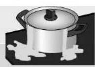
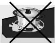
■ Pans that have already been used for cooking on a gas hob are no longer suitable for use on a ceramic hob.
■ Do not use aluminium foil, such as the trays from ready-made meals, for cooking food in. If aluminium foil melts on the cooking surface, it cannot be removed. Aluminium foil is also a very poor conductor of heat.
■Always pick pans up to move them.
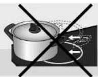
■ Sliding pans can cause scratches that cannot be removed.
■ Only place pans with clean, dry bottoms on the cooking surface. This will avoid causing stains that are difficult to remove.
■ Always keep the lid on the pan when cooking, in order to avoid energy loss.
■ Slide the bottom of the pan over a slightly damp cloth, before placing the pan on the cooking zone. This prevents dirt getting on to the cooking surface.
■ The cooking zone can be switched off 5 to 10 minutes before the end of the cooking time. The dish will then finish cooking on the residual heat, provided you keep the lid on the pan.

Cooking table
The table below is intended solely as a guide, because the heat setting depends on the quantity of food and the composition of the pan.
Use the highest setting for:
■ bringing to the boil quickly;
■ shrinking down leaf vegetables;
■ blanching vegetables;
■ heating oil, fat and butter;
■ frying steak (rare, red);
■ pressurising a pressure cooker;
■ cooking smooth blancmange and custard
Use a slightly lower setting for:
■ scaring meal;
■ frying flatfish, slices or fillet;
■ frying cooked potatoes;
■ cooking smooth, thickened soups and sauces;
■ frying omelettes;
■ frying beef steak (medium, pink-red);
■ deep frying (depending on the temperature and the quantity).
Use a setting slightly above the average setting for:
■ cooking of thick pancakes;
■ frying thick pieces of meat in breadcrumbs;
■ cooking through thin pieces of meat;
■ broiling large pieces of meat;
■ frying blocks of ham or bacon;
■ frying raw potatoes;
■ frying fish coated with breadcrumbs;
■ frying beef clives;
■ frying omelettes.
Use the medium settings for:
■completing the cooking of large quantities;
■ defrosting firm vegetables (French beans, for example)
Use the lowest settings for:
■simmering bouillon;
■ slowing pears;
■ preparing meat stew;
■completing the cooking of dishes;
■braising vegetables.
Pelgrim
General
Clean the cooking appliance after each use. You can use a mild cleaning agent for this - for example, washing-up liquid. Always clean the hobs after use. You can use a mild cleaning agent, such as washing-up liquid, for this purpose. Special cleaning agents for ceramic hobs have the advantage that a thin film remains on the glass surface so that over-cooked food and lime scale are less likely to get burnt into the hob, making it easier to clean the next time. It is best to let the hob cool down before cleaning it. Over-cooked food containing a lot of sugar and acids, such as apple sauce, rhubarb or red cabbage are best removed immediately with a damp dish cloth to prevent them getting burnt into the hob. Be careful with the hot cooking zone!
You can use a glass-scraper to remove obstinate food residue.
Traces of metals (due to sliding pans) can be difficult to remove Special products are available for removing traces of metal.
Never use
You should never use scouring agents. These cause scratches in which lime deposits and dirt can accumulate.
Never use sharp objects such as steel wool and scourers.
For cleaning tips refer to the internet site 'www.hps.nl'.
Table
If the appliance does not work properly, this does not always mean that it is defective. Try to deal with the problem yourself first.
Phone the service department if the advice given below does not help. Only authorised personnel may open the appliance or carry out work on the mains power supply.
Damage caused by incorrect connection, incorrect installation or incorrect use is not covered by the warranty.
| Fault | Cause | Solution |
| Cooking zones do not get hot. | - Appliance incorrectly connected.- Plug not, or not completely, in the socket.- Fuse(s) in the meter cupboard defective. | - See the installation instructions for correct connection.- Put the plug into the socket- Check the fuses in the meter cupboard. |
| Error codes F00-F12 in the display. | - A button is defective or dirty or there is an object on top of it. Each button has its own number, from 00 to 12. The number associated with the button appears in the display. | - Clean the appliance. Do not place any objects on the control panel. |
| Error code F3 appears. | - Transistors overheated.- The appliance has insufficient ventilation. | - Allow the appliance to cool down until the code disappears.- Make sure there is sufficient ventilation. |
| Error code F99 appears. | - Two or more buttons were operated for a long time. | - Do not operate more than one button at the same time. |
| Spontaneous change of setting selected. | - Pan too close to buttons. | - Make sure that pan is at least 20 mm from buttons. |


In the case of faults visit the internet site www.hps.nl.
environmental aspects

Pelgrim
installation guide
Pelgrim
Disposal of packaging / appliance
In the manufacturing of this appliance use has been made of durable materials. At the end of its lifecycle this appliance must be disposed of in a responsible manner. The authorities can advise you on this.
The appliance packaging is recyclable. The following may have been used:
cardboard;
■ polythene film (PE);
■ CFC-free polystyrene (PS hard foam).
Dispose of these materials responsibly and in accordance with government regulations.
General
This appliance meets all relevant CE guidelines.
The data plate on the underside of the appliance indicates the total nominal load, the required voltage and the frequency.
Safety
This appliance should only be connected up by a registered electrical installer! The electrical connection must comply with national and local regulations. The appliance should always be earthed.
Damage caused by incorrect connection, incorrect use or incorrect building in is not covered by the guarantee.
For correct operation of the appliance it is important that:
■ the power cable hangs freely and is not struck by a drawer;
■ the worktop is level.

The walls and the worktop around the appliance must be made of heat resistant (>85°C) material. Even if the appliance itself does not get hot, the heat from a hot frying pan, for instance, could cause discolouring or damage to the wall or worktop.

Pelgrim

Pelgrim
Electrical connection
For the connection, use an approved cable, in accordance with the regulations. The cable casing should be of rubber.
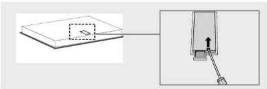
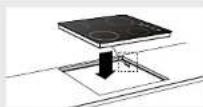
There is a label on the underside of the appliance with the wiring diagrams. The connection terminals are accessible once you have opened the junction box on the underneath. The junction box cover can be opened with a screwdriver.
natural_image
Diagram showing a component being inserted into a device, with an arrow indicating the insertion direction (no text or symbols present)If you want to make a fixed connection, make sure that a multi-polar switch with a contact separation of at least 3 mm is fitted in the supply line.
Power setting table
| Type of hob CKT745 CKT755 CKT770 | ||
| Cooklight x x x | ||
| Electrical connection | ||
| 730 V - 50 Hz x x x | ||
| Power of element | ||
| Front left 2300 W | ||
| Front left double 2200 / | 1000 W 2200 / 1000 W | |
| Rear left 1200 W 1200 W | 1200 W | |
| Rear right 2000 W 2000 W | ||
| Rear right fish pan | 2200 / 1400 W | |
| Front right | 1200 W 1200 W 2000 W |
The appliance can be connected in the following ways:
1 phase connection (1 1N a.c. 230 V / 50 Hz):
The voltage between live and neutral is 230 V a.c.
Install connecting bridges between connection points 1-2 and 4-5.
Your group must be protected by a fuse of at least 32 A. The connecting power cable must have a minimum core cross section of 6 mm².
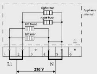
text_image
right rear right front left front left rear Appliance internal 1 2 3 4 5 6 1.1 N 230 V2 lives with 2 neutrals connection (2 2N a.c. 230 V / 50 Hz):
The voltage between live and neutral is 230 V a.c. There may be a voltage of 0 V between the phases if they are connected to the same phase in the meter cupboard but also 400 V if they are connected to 2 different phases. Your groups must be fused with at least 16 A (2x). The connecting power cable must have a minimum core cross section of 2.5 mm ^2 .
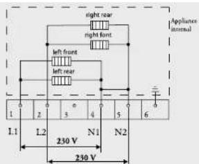
text_image
Appliance internal right rear right front left front left rear 1 2 3 4 5 6 L1 L2 N1 N2 230 V 230 V
Pelgrim

Pelgrim
2 lives with 1 neutral connection (2 1N a.c. 400 V / 50 Hz):
The voltage between the phases and the neutral is 230 V a.c. Between the lives there is a voltage of 400 V. If there is not a voltage of 400 V between the lives, two wires have been taken from the same live in the meter cupboard and the hob must be connected with two neutral wires, as indicated above under 2 lives with 2 neutrals. Install a connecting bridge between the connection points 4-5. Your groups must be fused with at least 16 A (2x). The connecting power cable must have a minimum core cross section of 2.5 mm ^2 .
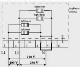
text_image
Appliance internal right rear right front left front left rear 1 2 3 4 5 6 L1 L2 230 V N 400 V 230 V3 lives with 1 neutral connection (3 1N a.c. 400 V / 50 Hz):
The voltage between the phases and the neutral is 230 V a.c. There is a voltage of 400 V between the lives. Fit a connecting bridge between the connection points 4-5. Phase 3 carries no load. Your groups must be fused with at least 16 A (3x). The connecting power cable must have a minimum core cross section of 2.5 mm ^2 .
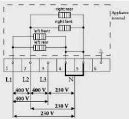
text_image
Appliance internal right rear right front left front left rear 1 2 3 4 5 6 L1 L2 L3 N 400 V 400 V 250 V 400 V 230 V 230 V3-phase connection (3 a.c. 230 V / 50 Hz):
The voltage between the phases and the neutral is 230 V a.c. Install connecting bridges between the connection points 4-5. Uw groepen mooten afgezekerd zijn met minimaal 16 A (3x). The connecting power cable must have a minimum core cross section of 2,5 mm ^2 .
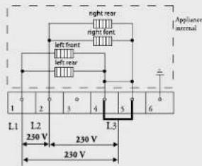
text_image
night rear night front left front left rear Applancer accrual L1 L2 250 V 230 V L3 230 VYou can use the bridges provided on the connecting block to make the required interconnections as indicated in the preceding illustrations. How to install the bridges is indicated in the junction box cover and in the illustration below. The bridges should not be placed immediately on top of the connecting wires, but between the screw-head and the clamp around the connecting wire.
Secure the cable with the strain relief and close the cover.


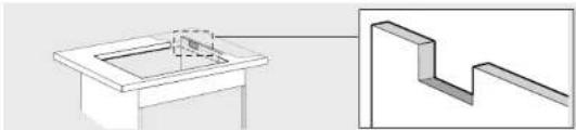
Building in
Cut opening in worktop
Saw the opening in the worktop. This should be done very accurately (see table). Also saw out any partitions that may be present.
The distance from the saw line to the rear wall and/or side wall is indicated in the table.
Table
| Type of hob CKT745 CKT755 CKT770 | |||
| Appliance width x depth | |||
| 575 x 505 mm x | |||
| 600 x 510 mm x | |||
| 770 x 510 mm x | |||
| Installation height from top of worktop | |||
| 56 | x | ||
| 48 x x | |||
| Cut out dimensions width x depth | |||
| 560 x 490 mm x x | |||
| 750 x 490 mm x | |||
| Distance from saw line to rear wall 50 mm | 50 mm 50 mm | ||
| Distance from saw line to side wall 60 mm | 50 mm 50 mm |
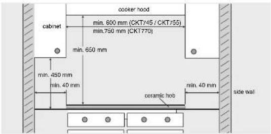
Space to be left free around the appliance
text_image
cooker hood cabinet min. 600 mm (CKT745 / CKT755) min.750 mm (CKT770) min. 650 mm min. 450 mm min. 40 min coramic hob min. 40 min side wallFitting the hob
Above a drawer or fixed decorative trim. Above a 60 cm ATAG oven. Above an oven of another make with casing cooling.
Ensure that there is a space of at least 10 mm between a drawer and the hob. Take care that the drawer cannot put any mechanical pressure on the connection cable.
Make an opening in the side wall of the kitchen cupboard for leading the connection cable through (for building-in in combination with an oven). This is necessary when the plug can no longer be reached after building in. Wall socket and plug must be accessible at all times.
natural_image
Technical diagram showing a 3D mechanical part with an inset view of a stepped structure (no text or symbols)A certain height under the worktop is necessary if the hob is installed above an oven. This height under the worktop depends on the following:
■Worktop thickness;
■Installed height of the hob (see table);
■ Height of oven at highest point (not including the operating panel).
The required height under the worktop is the height of the oven at the highest point plus the installed height of the hob less the worktop thickness.
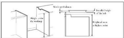
text_image
Window thickness Incremental height of the bar Height at one at higher point Height under the window
Pelgrim
Pelgrim
Above a 90 cm ATAG oven or an oven of another make without casing cooling.
Fit a heat-resistant (85 °C) plate to screen off the hob. Ensure that the space between the hob and the protective plate is ventilated. This space must not be connected with the space above the oven.
The space between the underside of the hob and the too of the protective plate must be at least 25 mm.
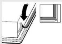
Sealing tape
Stick the sealing tape on the underside of the edge.
Don't stick the sealing tape around the corner; rather cut four pieces to lit effectively in the corners.
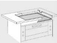
Turn the hob over and allow the appliance to sink into the opening.
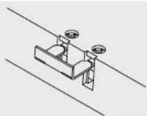
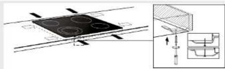
Only for CKT755
Secure the hob using the fasteners supplied. In the case of worktops thinner than 40 mm a filler block has to be used between the fasteners and the worktop. The screws must be screwed into the pressed holes.
text_image
Technical diagram showing a stator with four circular holes and a magnified inset of the component with internal structure.Connecting up and checking hob
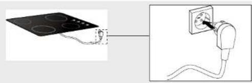
Make the electrical connection by inserting the plug in the socket or set the switch of the power supply cable (in the case of a fixed connection) to 1.
natural_image
Diagram showing a circuit board connected to an electrical outlet with wires, no text or symbols presentTest to check the hob is operational.