
WS 2200180 - Grinder AEG - Free user manual and instructions
Find the device manual for free WS 2200180 AEG in PDF.
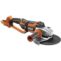
| Product type | Angle grinder (grinder) |
| Brand | AEG |
| Model | WS 2200180 |
| Disc diameter | 180 mm |
| Rated power | 2200 W |
| No-load speed | 8500 min⁻¹ |
| Spindle thread | M14 |
| Weight | 5.7 kg |
| Sound pressure level (K=3 dB) | 94.3 dB(A) |
| Sound power level (K=3 dB) | 105.3 dB(A) |
| Vibrations (cutting/rough grinding) | 7.6 m/s² (K=1.5 m/s²) |
| Vibrations (grinding) | 15.9 m/s² (K=1.5 m/s²) |
| Protection class | II |
| Power supply | Single-phase 230 V |
| Main applications | Grinding, cutting, sanding, wire brushing |
| Additional handle | Yes |
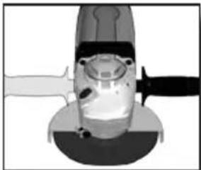
| Protective guard | Yes (supplied) |
| Recommended hearing protection | Yes |
| Maintenance | Clean ventilation slots regularly |
| Spare parts | Available from AEG after-sales service |
| Warranty | See enclosed brochure |
Frequently Asked Questions - WS 2200180 AEG
User questions about WS 2200180 AEG
0 question about this device. Answer the ones you know or ask your own.
Ask a new question about this device
Download the instructions for your Grinder in PDF format for free! Find your manual WS 2200180 - AEG and take your electronic device back in hand. On this page are published all the documents necessary for the use of your device. WS 2200180 by AEG.
USER MANUAL WS 2200180 AEG
Original instructions
natural_image
Exterior view of a silver AEG power tool with black handle and circular base (no text or symbols on the tool itself)
natural_image
Close-up of a mechanical device with a central hub and blade, no visible text or symbols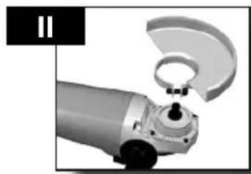
natural_image
Close-up of a robotic arm gripping a curved mechanical component (no visible text or symbols)
natural_image
Top-down view of a robotic arm with motion capture and control buttons, enclosed in a circular frame (no text or symbols visible)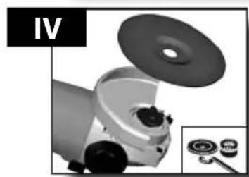
natural_image
Mechanical device with a lid and inset showing internal components (no text or symbols visible)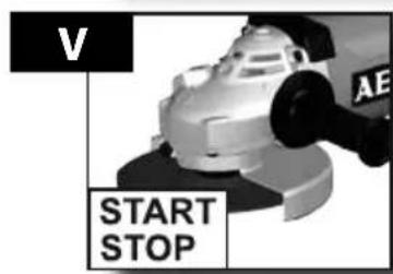
natural_image
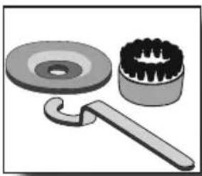
Illustration of a mechanical tool with a washer, gear, and handle (no text or symbols)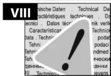
Accessory Zubehör Accessoires Accessorio orio • Acessório oren • Tilbehør • Tillbehör • Εξαρτήματα ar • Pînslušenstvn instv Wyposażenie a tartozékokat • Piederumi • Tarvikud итель • Аксесоари iu • ополнителна • 配件 • تاقجيم
natural_image
Close-up of a mechanical component with two hands operating it, no visible text or symbols
natural_image
3D rendering of a mechanical component with a tool inserted, showing internal structure and motion direction (no text or symbols)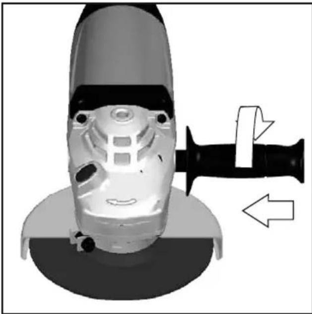
natural_image
Close-up of a mechanical device with a tool inserted, showing a face and blade assembly (no text or symbols visible)
natural_image
Cross-sectional diagram of a mechanical device with internal components and directional arrows (no text or symbols)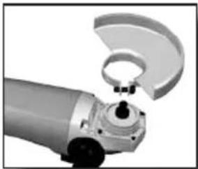
natural_image
Close-up of a robotic arm gripping a mechanical component (no visible text or symbols)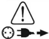

natural_image
Diagram of a mechanical device with an eye and surgical tool, no text or symbols present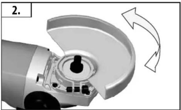
natural_image
Close-up of a robotic arm with a curved mechanical component and directional arrows indicating motion (no text or symbols)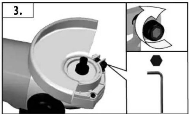
natural_image
Mechanical component diagram showing a cam and pin assembly with an arrow pointing to a cylindrical part (no text or symbols present)
natural_image
Mechanical component with a curved metallic part and internal gear mechanism (no visible text or symbols)For cutting-off operations!
Für Trennarbeiten!
natural_image
Close-up of a mechanical component with a circular base and radial blades (no visible text or symbols)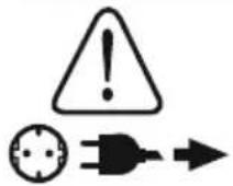


natural_image
Close-up of a mechanical device with a disc and inset showing mechanical components (no visible text or symbols)

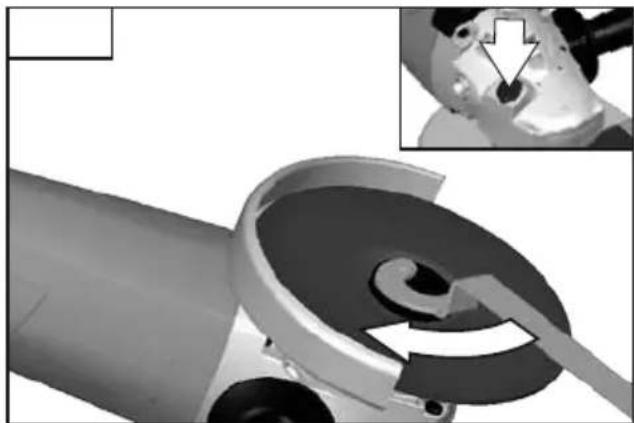
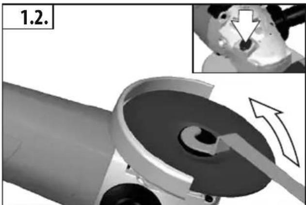
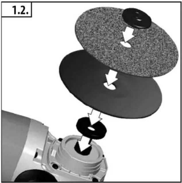
Use only spindle nuts as provided by the manufacturer. Do not use any keyless nuts!
natural_image
Close-up of a mechanical component with a highlighted section and arrow indicating a detail (no text or symbols)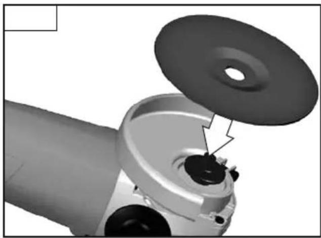
natural_image
Close-up of a mechanical component with a circular top and internal structure, showing no visible text or symbols.


natural_image
Close-up of a mechanical device with a disc and inset showing internal components (no visible text or symbols)
natural_image
Close-up of a mechanical component with a tool inserted, showing internal components and a magnified inset (no text or symbols visible)
natural_image
Mechanical component diagram showing a cutting tool interacting with a motor, with an inset close-up highlighting the machining process (no text or symbols present)
natural_image
Close-up of a mechanical component with a circular opening and a small inset showing a hole (no text or symbols visible)
natural_image
Close-up of a mechanical component with a highlighted part, showing internal components and a circular opening (no text or symbols)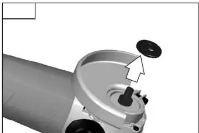
natural_image
Close-up of a mechanical component with a dial and handle, showing no visible text or symbols


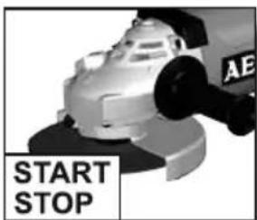
Start
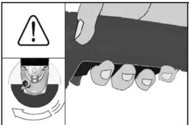
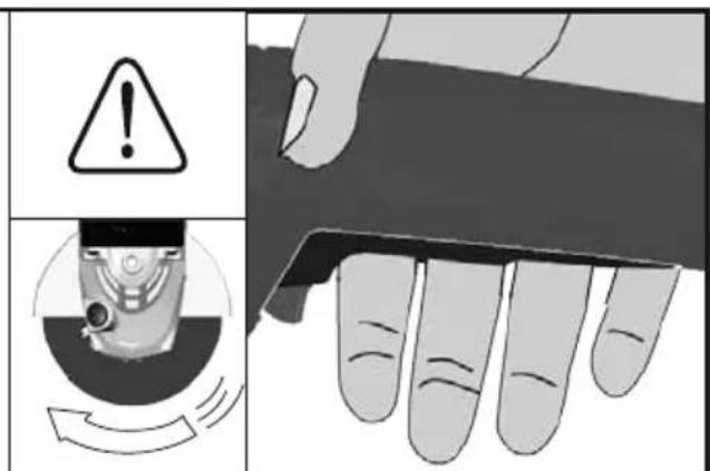
Stop

natural_image
Close-up of a mechanical tool interacting with a flat surface, showing no visible text or symbols.
natural_image
Blank gray image with no visible content, text, or symbols
natural_image
Illustration of a mechanical tool with a washer and gear (no text or symbols)Accessory
Zubehör
Accessoire
Accessorio
Accessorio
Acessório
Toebehoren
Tilbehør
Tilbehør
Tillbehör
Lisälaite
Εξαρτήματα
Aksesuar
Příslušenství
Príslušenstvo
Element
wyposażenia
dodatkowego
Tartozék
Oprema
Pribor
Papildus
aprikojums
Priedas
Tarvikud
Дополнитель
Аксесоар
Accesorii
Додатоци
配件
تاقحلم
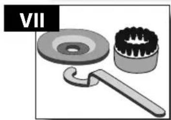
VII
natural_image
3D mechanical assembly diagram showing a robotic arm with internal components and directional arrows (no text or symbols)
natural_image
Mechanical assembly diagram showing a motor with gear meshing and a close-up inset of a mechanical component (no text or symbols visible)
natural_image
Mechanical assembly diagram showing a motor with gear-like components and a close-up of a mechanical component (no text or symbols visible)
natural_image
3D mechanical assembly diagram showing a motor and gear assembly with arrows indicating motion (no text or symbols)


natural_image
Illustration of a mechanical tool with a washer and brush (no text or symbols)Accessory
Zubehör
Accessoire
Accessorio
Accessorio
Acessório
Toebehoren
Tilbehør
Tilbehør
Tillbehör
Lisälaite
Εξαρτήματα
Aksesuar
Příslušenství
Príslušenstvo
Element
wyposażenia
dodatkowego
Tartozék
Oprema
Pribor
Papildus
aprikojums
Priedas
Tarvikud
Дополнитель
Аксесоар
Accesorii
Додатоци
配件
تاقحلم
natural_image
Mechanical assembly diagram showing a motor and three circular components with arrows indicating motion (no text or symbols)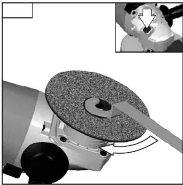
natural_image
Mechanical assembly diagram showing a grinding machine with a circular workpiece and tool interacting with it, accompanied by an inset close-up of a robotic arm (no text or symbols visible)
natural_image
Close-up of a mechanical component with a downward arrow pointing to a central feature (no visible text or symbols)
natural_image
Mechanical component with a rotating disc and tool, showing a close-up view of a mechanical part (no text or symbols visible)
natural_image
Close-up of a robotic arm with a white arrow pointing to a circular feature (no text or symbols visible)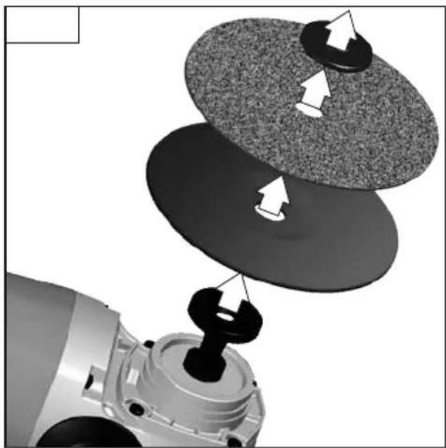
natural_image
Mechanical assembly diagram showing a motor and three circular components with directional arrows indicating motion (no text or symbols)WS 2200 WS 2200-180 WS 2200-230
| Rated input | 2200 | W | 2200 | W |
| Rated speed | 8500 | min^-1 | 6600 | min^-1 |
| Grinding disk diameter | 180 | mm | 230 | mm |
| Thread of work spindle | M | 14 | M | 14 |
| Weight according EPTA-Procedure 01/2003 | 5,7 | kg | 5,8 | kg |
Noise/Vibration Information
Measured values determined according to EN 60 745.
Typically, the A-weighted noise levels of the tool are:
Sound pressure level (K=3 dB(A)). 94,3 dB (A) 94,3 dB (A)
Sound power level(K=3 dB(A))....105,3 dB (A)....105,3 dB (A)
Wear ear protectors!
Total vibration values (vector sum in the three axes) determined according to EN 60745.
Surface grinding: vibration emission value a_b 7,6 m/s ^2 7,6 m/s ^2
Uncertainty K....1,5 m/s ^2 ....1,5 m/s ^2
Disk sanding: vibration emission level a_h .....15,9 m/s ^2 .....15,9 m/s ^2
Uncertainty K....1,5 m/s ^2 ....1,5 m/s ^2
For other applications, e.g. Abrasive Cutting-Off Operations or Wire Brushing other vibration values could occur.
WARNING
The vibration emission level given in this information sheet has been measured in accordance with a standardised test given in EN 60745 and may be used to compare one tool with another. It may be used for a preliminary assessment of exposure.
The declared vibration emission level represents the main applications of the tool. However if the tool is used for different applications, with different accessories or poorly maintained, the vibration emission may differ. This may significantly increase the exposure level over the total working period. An estimation of the level of exposure to vibration should also take into account the times when the tool is switched off or when it is running but not actually doing the job. This may significantly reduce the exposure level over the total working period.
Identify additional safety measures to protect the operator from the effects of vibration such as: maintain the tool and the accessories, keep the hands warm, organisation of work patterns.

WARNING!
Read all safety warnings and all instructions, including those given in the accompanying brochure. Failure to follow the warnings and instructions may result in electric shock, fire and/or serious injury.
Save all warnings and instructions for future reference.
SAFETY INSTRUCTIONS
Safety Warnings Common for Grinding, Sanding, Wire Brushing or Abrasive Cutting-Off Operations:
a) This power tool is intended to function as a grinder, sander, wire brush, or cut-off tool. Read all safety warnings, instructions, illustrations and specifications provided with this power tool.
Failure to follow all instructions listed below may result in electric shock, fire and/or serious injury.
b) Operations such as polishing are not recommended to be performed with this power tool. Operations for which the power tool was not designed may create a hazard and cause personal injury.
c) Do not use accessories which are not specifically designed and recommended by the tool manufacturer. Just because the accessory can be attached to your power tool, it does not assure safe operation.
d) The rated speed of the accessory must be at least equal to the maximum speed marked on the power tool. Accessories running faster than their rated speed can break and fly apart.
e) The outside diameter and the thickness of your accessory must be within the capacity rating of your power tool. Incorrectly sized accessories cannot be adequately guarded or controlled.
f) The arbour size of wheels, flanges, backing pads or any other accessory must properly fit the spindle of the power tool.
Accessories with arbour holes that do not match the mounting hardware of the power tool will run out of balance, vibrate excessively and may cause loss of control.
g) Do not use a damaged accessory. Before each use inspect the accessory such as abrasive wheels for chips and cracks, backing pad for cracks, tear or excess wear, wire brush for loose or cracked wires. If power tool or accessory is dropped, inspect for damage or install an undamaged accessory. After inspecting and installing an accessory, position yourself and bystanders away from the plane of the rotating accessory and run the power tool at maximum noload speed for one minute. Damaged accessories will normally break apart during this test time.
h) Wear personal protective equipment. Depending on application, use face shield, safety goggles or safety glasses. As appropriate, wear dust mask, hearing protectors, gloves and shop apron capable of stopping small abrasive or workpiece fragments. The eye protection must be capable of stopping flying debris generated by various operations. The dust mask or respirator must be capable of filtrating particles generated by your operation. Prolonged exposure to high intensity noise may cause hearing loss.
i) Keep bystanders a safe distance away from work area. Anyone entering the work area must wear personal protective equipment. Fragments of workpiece or of a broken accessory may fly away and cause injury beyond immediate area of operation.

j) Hold power tool by insulated gripping surfaces, when performing an operation where the cutting accessory may contact hidden wiring or its own cord. Cutting accessory contacting a „live“ wire may make exposed metal parts of the power tool „live“ and could give the operator an electric shock.
k) Position the cord clear of the spinning accessory. If you lose control, the cord may be cut or snagged and your hand or arm may be pulled into the spinning accessory.
I) Never lay the power tool down until the accessory has come to a complete stop. The spinning accessory may grab the surface and pull the power tool out of your control.
m) Do not run the power tool while carrying it at your side. Accidental contact with the spinning accessory could snag your clothing, pulling the accessory into your body.
n) Regularly clean the power tool's air vents. The motor's fan will draw the dust inside the housing and excessive accumulation of powdered metal may cause electrical hazards.
o) Do not operate the power tool near flammable materials. Sparks could ignite these materials.
p) Do not use accessories that require liquid coolants. Using water or other liquid coolants may result in electrocution or shock.
Kickback and related warnings
Kickback is a sudden reaction to a pinched or snagged rotating wheel. Pinching or snagging causes rapid stalling of the rotating wheel which in turn causes the uncontrolled power tool to be forced in the direction opposite of the wheel's rotation at the point of the binding.
For example, if an abrasive wheel is snagged or pinched by the workpiece, the edge of the wheel that is entering into the pinch point can dig into the surface of the material causing the wheel to climb out or kick out. The wheel may either jump toward or away from the operator, depending on direction of the wheel's movement at the point of pinching. Abrasive wheels may also break under these conditions.
Kickback is the result of saw misuse and/or incorrect operating procedures or conditions and can be avoided by taking proper precautions as given below.
a) Maintain a firm grip on the power tool and position your body and arm to allow you to resist kickback forces. Always use auxiliary handle, if provided, for maximum control over kickback or torque reaction during start-up. The operator can control torque reactions or kickback forces, if proper precautions are taken.
b) Never place your hand near the rotating accessory. Accessory may kickback over your hand.
c) Do not position your body in the area where power tool will move if kickback occurs. Kickback will propel the tool in direction opposite to the wheel's movement at the point of snagging.
d) Use special care when working corners, sharp edges, etc. Avoid bouncing and snagging the accessory. Corners, sharp edges or bouncing have a tendency to snag the rotating accessory and cause loss of control or kickback.
e) Do not attach a saw chain, woodcarving blade or toothed saw blade. Such blades create frequent kickback and loss of control.
Safety Warnings Specific for Grinding and Abrasive Cutting-Off Operations:
a) Use only wheel types that are recommended for your power tool and the specific guard designed for the selected wheel.
Wheels for which the power tool was not designed cannot be adequately guarded and are unsafe.
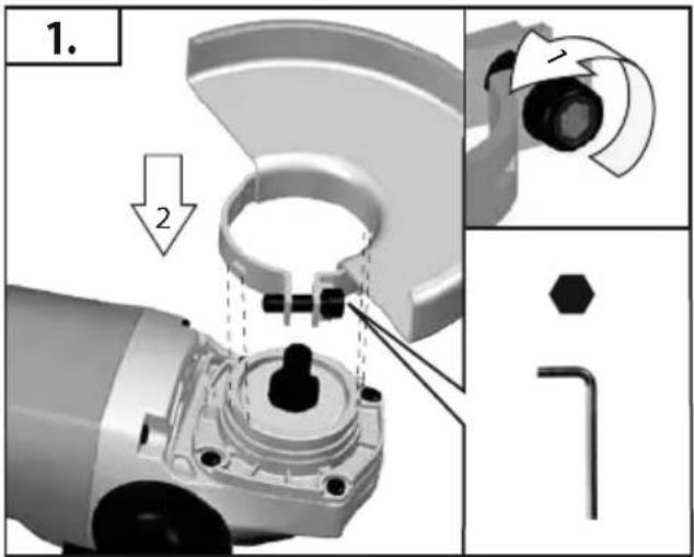
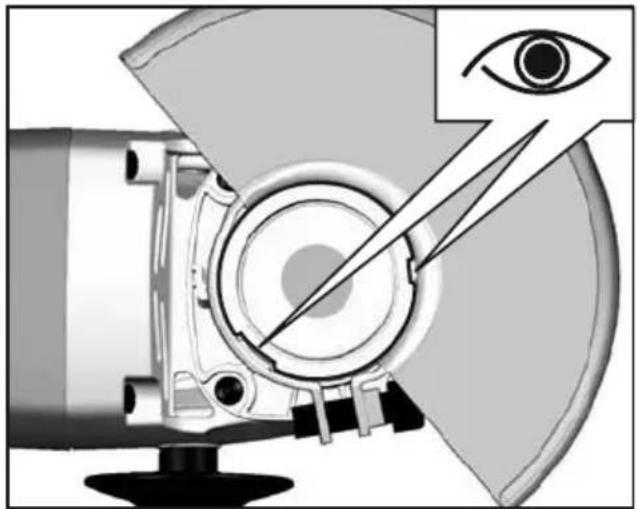
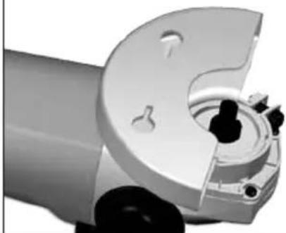
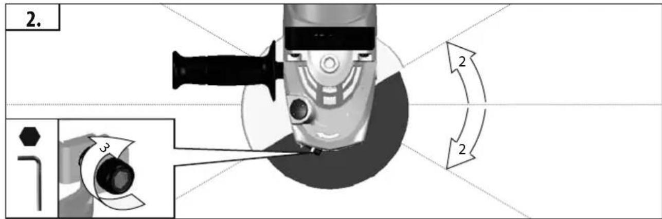
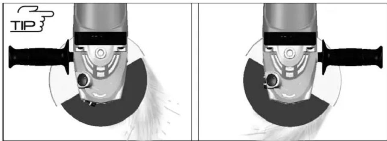
b) The guard must be securely attached to the power tool and positioned for maximum safety, so the least amount of wheel is exposed towards the operator. The guard helps to protect operator from broken wheel fragments and accidental contact with wheel.
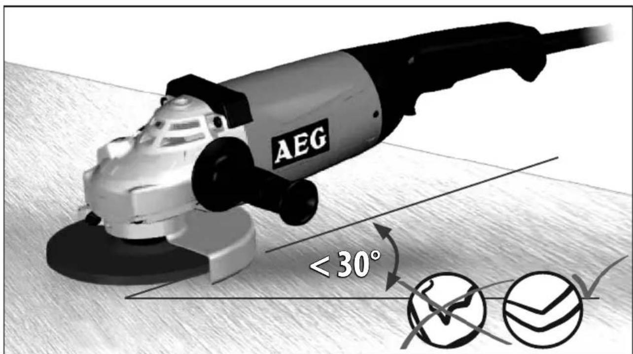
c) Wheels must be used only for recommended applications. For example: do not grind with the side of cut-off wheel. Abrasive cut-off wheels are intended for peripheral grinding, side forces applied to these wheels may cause them to shatter.
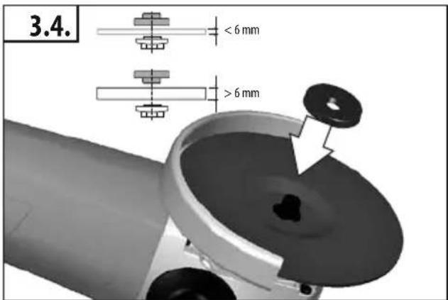
d) Always use undamaged wheel flanges that are of correct size and shape for your selected wheel. Proper wheel flanges support the wheel thus reducing the possibility of wheel breakage. Flanges for cut-off wheels may be different from grinding wheel flanges.
e) Do not use worn down wheels from larger power tools. Wheel intended for larger power tool is not suitable for the higher speed of a smaller tool and may burst.
Additional Safety Warnings Specific for Abrasive Cutting-Off Operations:
a) Do not "jam" the cut-off wheel or apply excessive pressure. Do not attempt to make an excessive depth of cut. Overstressing the wheel increases the loading and susceptibility to twisting or binding of the wheel in the cut and the possibility of kickback or wheel breakage.
b) Do not position your body in line with and behind the rotating wheel. When the wheel, at the point of operation, is moving away from your body, the possible kickback may propel the spinning wheel and the power tool directly at you.
c) When wheel is binding or when interrupting a cut for any reason, switch off the power tool and hold the power tool motionless until the wheel comes to a complete stop. Never attempt to remove the cut-off wheel from the cut while the wheel is in motion otherwise kickback may occur. Investigate and take corrective action to eliminate the cause of wheel binding.
d) Do not restart the cutting operation in the workpiece. Let the wheel reach full speed and carefully reenter the cut. The wheel may bind, walk up or kickback if the power tool is restarted in the workpiece.
e) Support panels or any oversized workpiece to minimize the risk of wheel pinching and kickback. Large workpieces tend to sag under their own weight. Supports must be placed under the workpiece near the line of cut and near the edge of the workpiece on both sides of the wheel.
f) Use extra caution when making a "pocket cut" into existing walls or other blind areas. The protruding wheel may cut gas or water pipes, electrical wiring or objects that can cause kickback.
Safety Warnings Specific for Sanding Operations:
a) Do not use excessively oversized sanding disc paper. Follow manufacturers recommendations, when selecting sanding paper. Larger sanding paper extending beyond the sanding pad presents a laceration hazard and may cause snagging, tearing of the disc or kickback.
Safety Warnings Specific for Wire Brushing Operations:
a) Be aware that wire bristles are thrown by the brush even during ordinary operation. Do not overstress the wires by applying excessive load to the brush. The wire bristles can easily penetrate light clothing and/or skin.
b) If the use of a guard is recommended for wire brushing, do not allow any interference of the wire wheel or brush with the guard. Wire wheel or brush may expand in diameter due to work load and centrifugal forces.
English
Appliances used at many different locations including open air should be connected via a residual current device (FI, RCD, PRCD) of 30mA or less.
Sawdust and splinters must not be removed while the machine is running. Only plug-in when machine is switched off.
Never reach into the danger area of the plane when it is running.
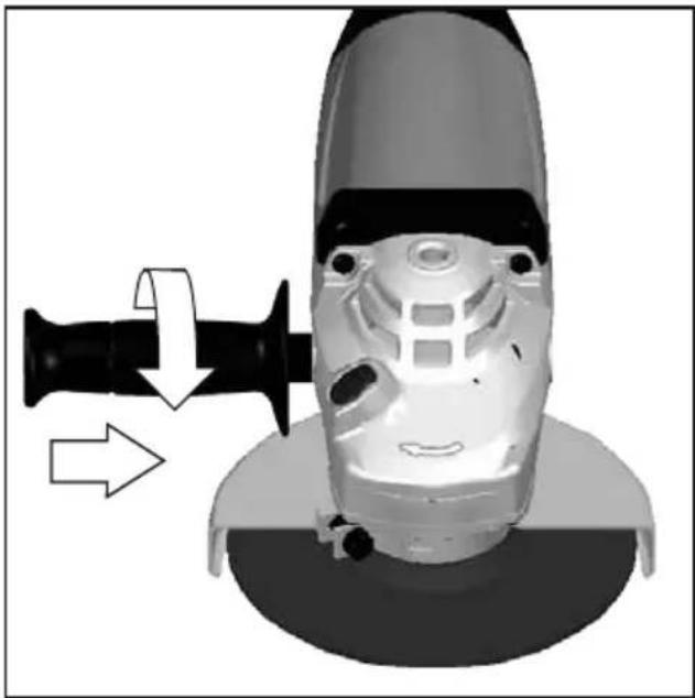
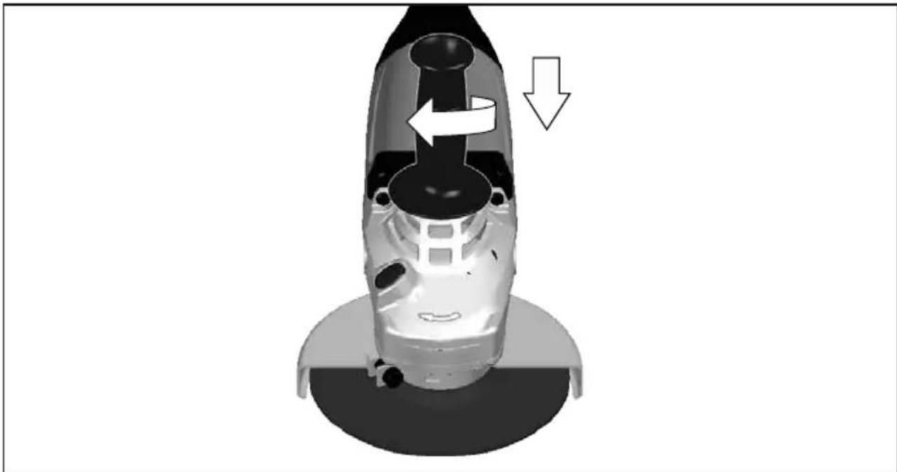
Always use the auxiliary handle.
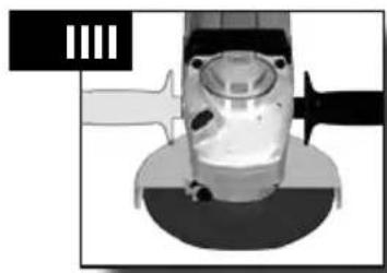
Always use the protecting cap when roughing-down and separating.
Immediately switch off the machine in case of considerable vibrations or if other malfunctions occur. Check the machine in order to find out the cause.
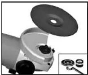
Always use and store the grinding disks according to the manufacturer's instructions.
When grinding metal, flying sparks are produced. Take care that no persons are endangered. Because of the danger of fire, no combustible materials should be located in the vicinity (spark flight zone). Do not use dust extraction.
Due care should be taken that no sparks or sanding dust flying from the workpiece come into contact with you.
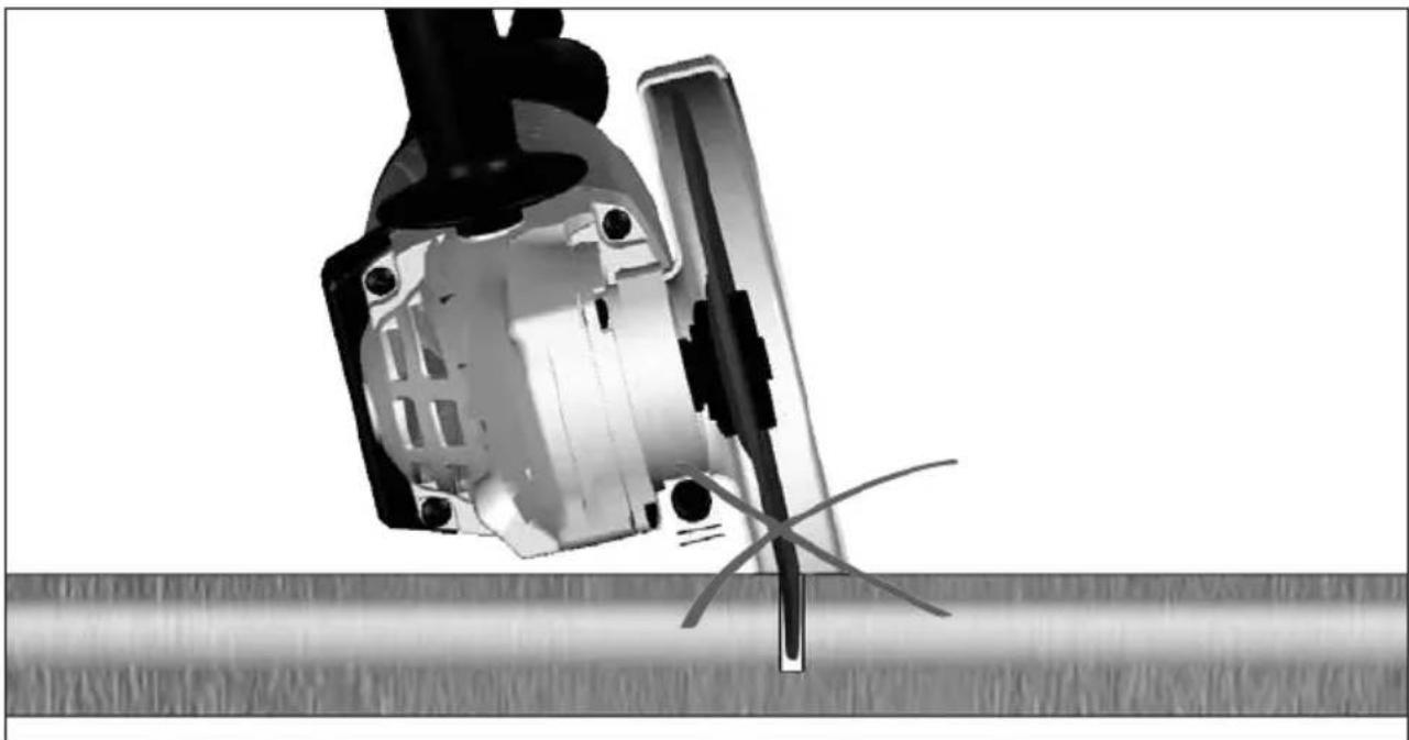
When separating stone the guide shoe must be used!
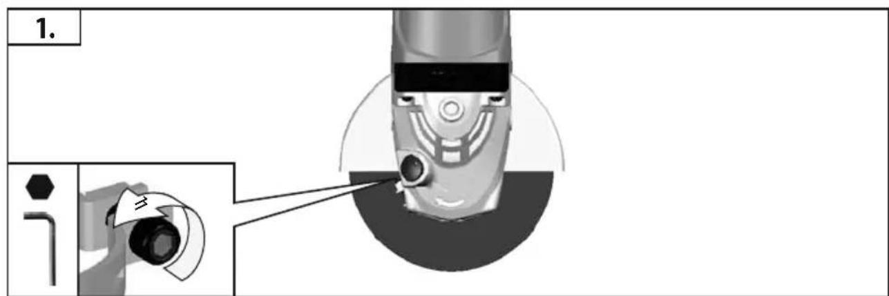
The adjusting nut must be tightened before starting to work with the machine.
The workpiece must be fixed if it is not heavy enough to be steady. Never lead the workpiece to the grinding disk with your hand.
Under extreme conditions (e.g. smooth-grinding metals with the arbour and vulcanized fibre grinding wheel), significant contamination can build up on the inside of the angle grinder. For safety reasons, in such conditions the inside should be cleaned thoroughly of metal deposits and a motor circuit-breaker must be connected in series. If the motor circuit-breaker trips the machine must be sent for repair.
For accessories intended to be fitted with threaded hole wheel, ensure that the thread in the wheel is long enough to accept the spindle length.
Use the safety guard from the accessories range when performing out cutting work.
SPECIFIED CONDITIONS OF USE
The angle grinder may be used for cutting, grinding, sanding and wire brushing a wide range of materials, such as metal or stone. If you have any doubts, please refer to the instructions supplied by the accessory manufacturer.
Do not use this product in any other way as stated for normal use.
MAINS CONNECTION

Connect only to single-phase AC current and only to the system voltage indicated on the rating plate. It is also possible to connect to sockets without an earthing contact as the design conforms to safety class II.
Inrush currents cause short-time voltage drops. Under unfavourable power supply conditions, other equipment may be affected. If the system impedance of the power supply is lower than 0,2 Ohm, disturbances are unlikely to occur.
MAINTENANCE
The ventilation slots of the machine must be kept clear at all times.
Do not let any metal parts enter the airing slots - danger of short circuit! Use only AEG accessories and spare parts. Should components need to be replaced which have not been described, please contact one of our AEG service agents (see our list of guarantee/service addresses).
If needed, an exploded view of the tool can be ordered. Please state the Article No. as well as the machine type printed on the label and order the drawing at your local service agents or directly at: AEG Electric Tools GmbH, Max-Eyth-Straße 10, D-71364 Winnenden, Germany
SYMBOLS

Please read the instructions carefully before starting the machine.

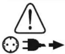
CAUTION! WARNING! DANGER!

Always wear goggles when using the machine.

Always disconnect the plug from the socket before carrying out any work on the machine.

Accessory - Not included in standard equipment, available as an accessory.
Do not dispose of electric tools together with household waste material! In observance of European Directive 2002/96/EC on waste electrical and electronic equipment and its implementation in accordance with national law, electric tools that have reached the end of their life must be collected separately and returned to an environmentally compatible recycling facility.
WS 2200 WS 2200-180 WS 2200-230
OPGELET! WAARSCHUWING! GEVAAR!

UPORABA V SKLADU Z NAMEMBNOSTJO
SPETSIAALSED TURVAJUHISED


- Start
- Stop
- Noise/Vibration Information
- Wear ear protectors!
- WARNING
- WARNING!
- SAFETY INSTRUCTIONS
- Kickback and related warnings
- Safety Warnings Specific for Grinding and Abrasive Cutting-Off Operations:
- Additional Safety Warnings Specific for Abrasive Cutting-Off Operations:
- Safety Warnings Specific for Sanding Operations:
- Safety Warnings Specific for Wire Brushing Operations:
- English
- SPECIFIED CONDITIONS OF USE
- MAINS CONNECTION
- MAINTENANCE
- SYMBOLS
- UPORABA V SKLADU Z NAMEMBNOSTJO
- SPETSIAALSED TURVAJUHISED
Brand : AEG
Model : WS 2200180
Category : Grinder