
BEWS 18-230BL - Grinder AEG - Free user manual and instructions
Find the device manual for free BEWS 18-230BL AEG in PDF.

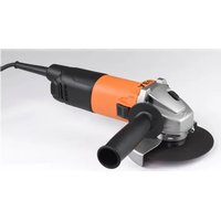
| Product type | Cordless angle grinder |
| Brand | AEG |
| Model | BEWS 18-230BL |
| Nominal voltage | 18 V |
| No-load speed | 5500 min⁻¹ |
| Maximum grinding disc diameter | 230 mm |
| Disc bore diameter | 22.2 mm |
| Cutting disc thickness (min./max.) | 1.9 / 3 mm |
| Maximum polishing disc thickness | 8 mm |
| Battery type | Interchangeable lithium-ion (GBS system) |
| Battery capacity | Compatible with 18 V batteries from the range |
| Main functions | Grinding, cutting, sanding, wire brushing, polishing |
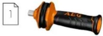
| Safety | Anti-restart protection, soft start, protective guard, auxiliary handle |
| Maintenance and cleaning | Regularly clean ventilation slots; remove battery before any maintenance |
| Spare parts and repairability | Use only AEG parts; contact AEG service for repairs |
| General information | Category: grinder; professional use; anti-vibration system |
Frequently Asked Questions - BEWS 18-230BL AEG
User questions about BEWS 18-230BL AEG
0 question about this device. Answer the ones you know or ask your own.
Ask a new question about this device
Download the instructions for your Grinder in PDF format for free! Find your manual BEWS 18-230BL - AEG and take your electronic device back in hand. On this page are published all the documents necessary for the use of your device. BEWS 18-230BL by AEG.
USER MANUAL BEWS 18-230BL AEG
Original instructions
natural_image
Orange AEG power tool with black handle and gray base, no visible text or symbols on the device itself
natural_image
Close-up of a mechanical lever with orange and black components, no visible text or symbols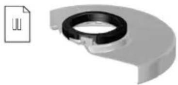
natural_image
3D rendered mechanical component with a black ring and a document icon on the left (no text or symbols on the main subject)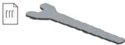
natural_image
3D rendered mechanical part with a close-up of its edge detail (no text or symbols)
natural_image
Illustration of a mechanical device with orange and black components, no visible text or symbols
natural_image
Close-up of a mechanical component with an arrow indicating rotation or assembly (no visible text or symbols)
natural_image
Close-up of a robotic arm with a metallic clamp and orange base (no visible text or symbols)
natural_image
Top-down view of a mechanical device with orange and silver components, no visible text or symbols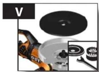
natural_image
Close-up of industrial cleaning tools including a power tool, disc, and gear assembly (no visible text or symbols)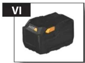
natural_image
Black rectangular electronic component with orange highlights, labeled 'VI' in top-left corner (no other text or symbols)
natural_image
Illustration of a wrench, a washer, and a gear-like component (no text or symbols)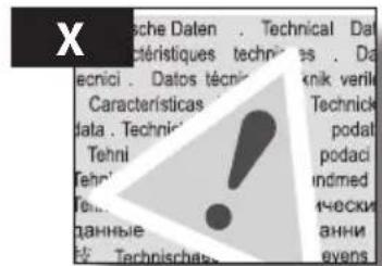
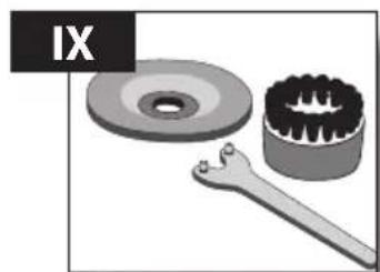
Accessory Zubehör Accessoires Accessorio
natural_image
3D rendered mechanical component with orange and black parts, no visible text or symbols

natural_image
3D rendering of a power tool with orange and gray components, showing internal flow arrows (no text or symbols)
natural_image
Cross-sectional diagram of a mechanical device with internal components and directional arrows indicating motion (no text or symbols)
natural_image
Close-up of a mechanical device with orange and black components, no visible text or symbols

natural_image
Close-up of a robotic arm with a metallic component and orange base (no visible text or symbols)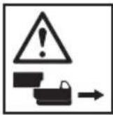
natural_image
Close-up of an orange AEC robotic grinding machine with a mechanical component, showing no visible text or symbols.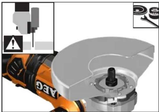
natural_image
Close-up of a mechanical power tool with warning symbols and exploded view (no readable text or labels)
natural_image
Close-up of a NE6 electric motor with mechanical components, showing assembly detail (no text or symbols)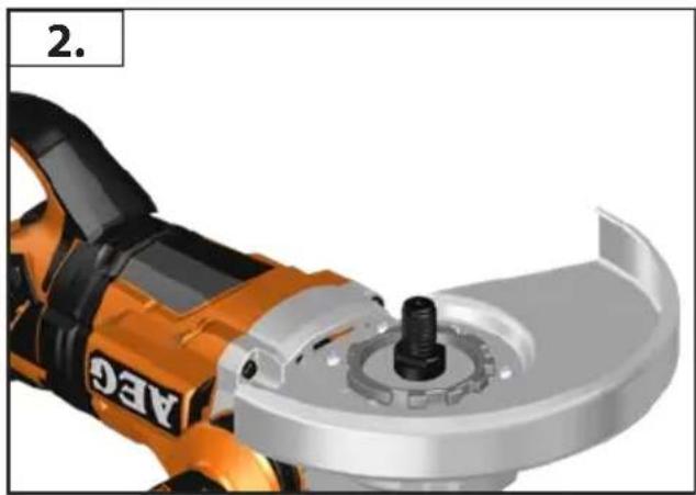
natural_image
Close-up of an orange AEC power saw with a mechanical component (no text or symbols visible)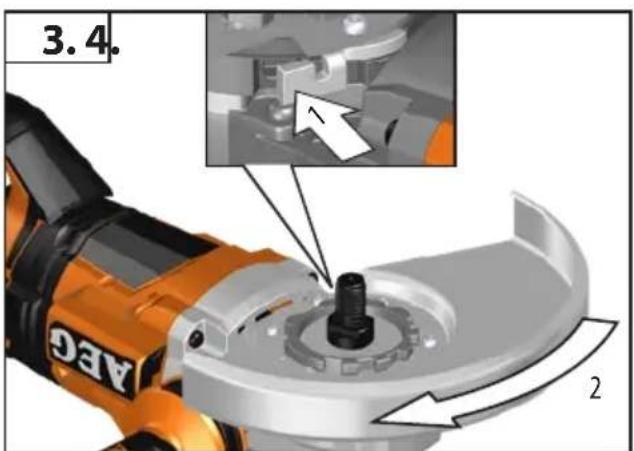
natural_image
Top-down view of a mechanical tool with orange and silver components, no visible text or symbols
natural_image
Technical illustration of a mechanical device with orange and black components, no visible text or symbols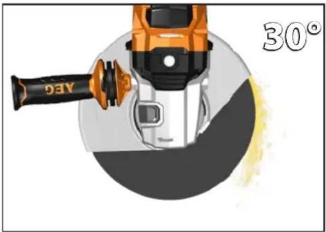
natural_image
Illustration of a welding torch with a 30° angle indicator, showing mechanical components without any text or symbols on the diagram itself.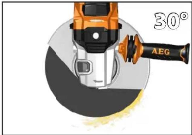
natural_image
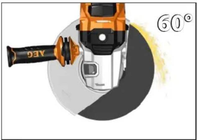
Illustration of a power saw cutting a circular blade with a 60° angle indicator (no text or symbols on the diagram itself)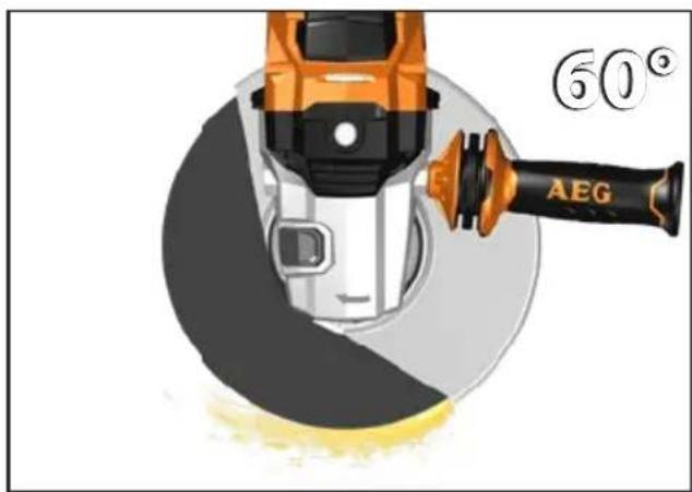
natural_image
Close-up of industrial tools including a grinding machine and mechanical components (no visible text or symbols)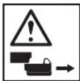

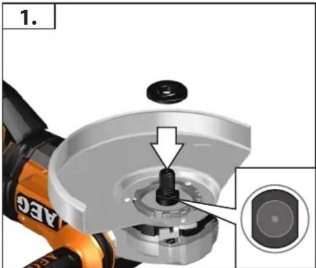
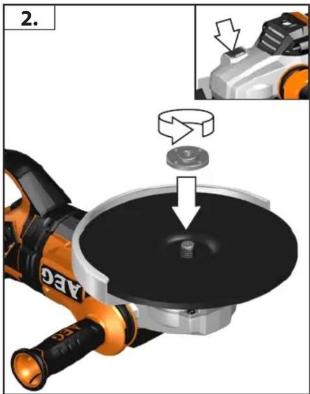
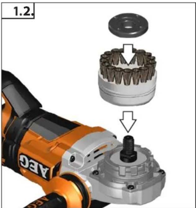
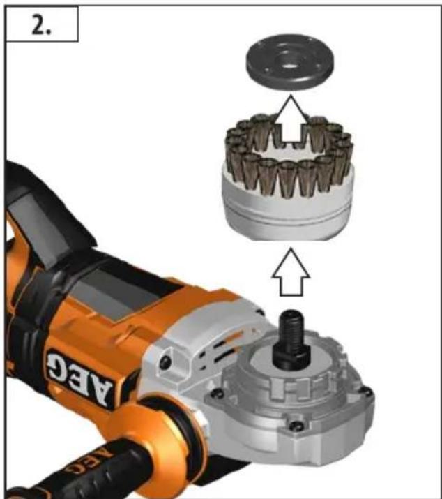
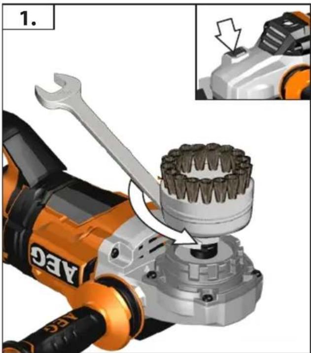
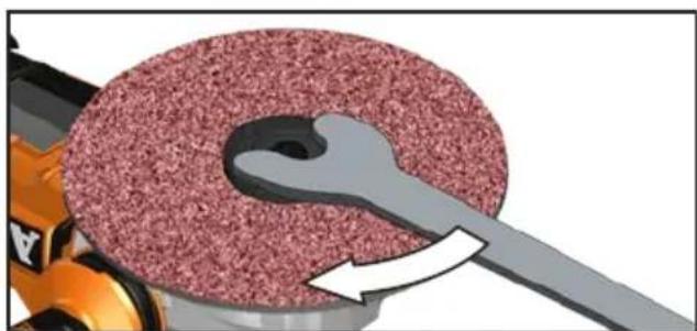
Use only spindle nuts as provided by the manufacturer. Do not use any keyless nuts!
natural_image
Product photo of a robotic grinding tool with mechanical components (no visible text or symbols)


natural_image
Close-up of mechanical components including a power tool, disc, washer, and wrench (no visible text or symbols)

natural_image
Close-up of a power tool's internal components, showing disc and base assembly (no text or symbols visible)
natural_image
Black rectangular electronic component with orange highlights (no visible text or symbols)
natural_image
Illustration of a power crimping tool and its internal component, showing the tool's handle and part (no text or symbols)
natural_image
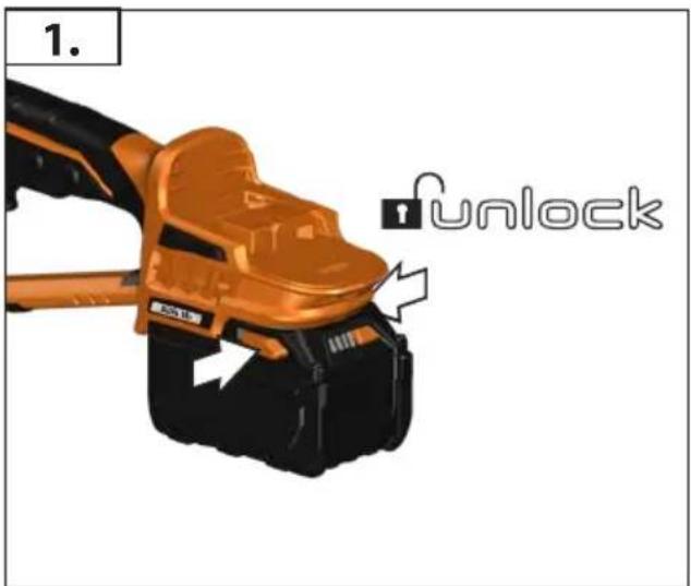
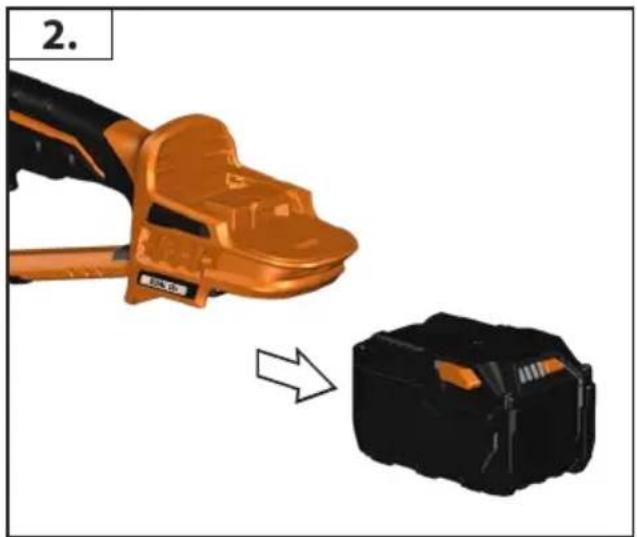
Illustration of a hand holding an orange tool next to a black device with an arrow indicating transformation (no text or symbols)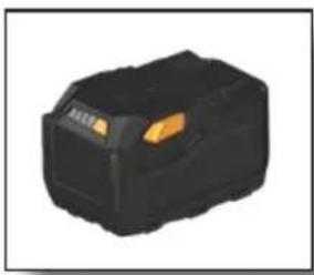
natural_image
Black rectangular electronic component with orange highlights (no visible text or symbols)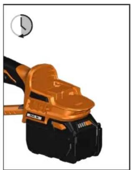
natural_image
Illustration of a mechanical device with orange and black casing, no visible text or symbols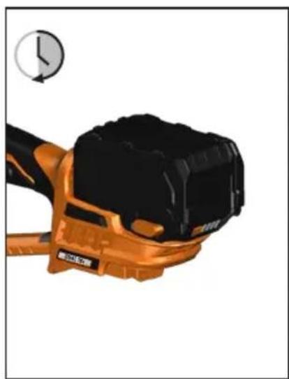
natural_image
Close-up of a black and orange industrial tool with a circular gauge indicator (no visible text or symbols)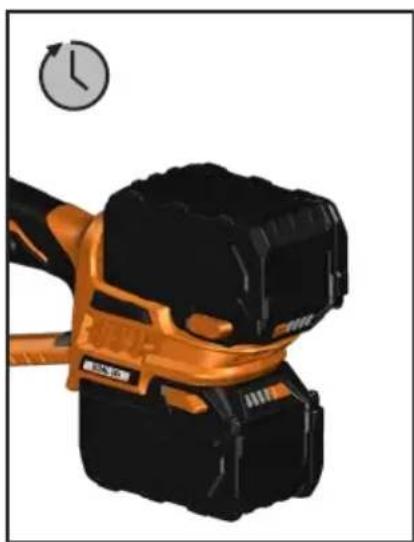
natural_image
Illustration of a black and orange handheld device with a clock icon above (no text or symbols on the device itself)
natural_image
Illustration of a hand pointing at a black electronic device with a yellow button (no text or symbols visible)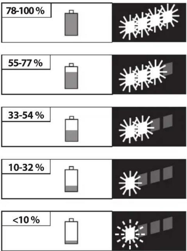
bar
| Category | Percentage (%) | | :--- | :--- | | 78-100% | [Estimated from visual bar] | | 55-77% | [Estimated from visual bar] | | 33-54% | [Estimated from visual bar] | | 10-32% | [Estimated from visual bar] | | <10% | [Estimated from visual bar] |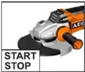

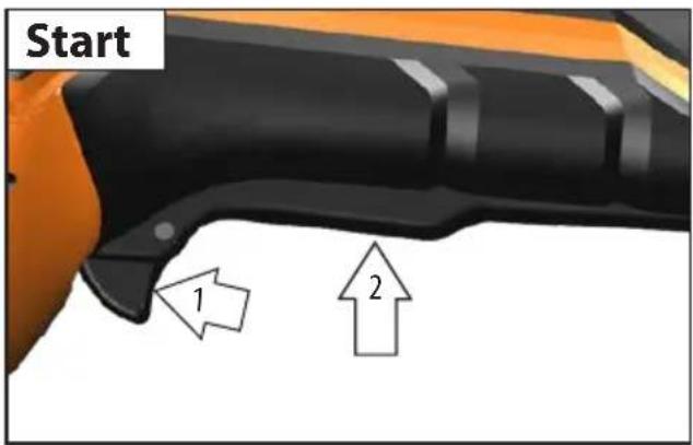
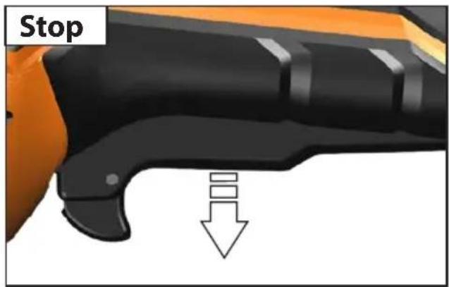
Switch cannot be locked
natural_image
Two-step illustration showing a hand holding an orange electric shock absorber and a black plastic case with an arrow indicating the process (no text or symbols)

Steady Red
Kontinuierlich Rot
Fixe Rouge
Fisso Rosso
Encendido Rojo
Sólido Vermelho
Continu Rood
Lyser konstant Rød
Konstant Rødt
Enfärgad Röd
Jatkuva Punainen
Μονόχρωμο Κόκκινο
Sağlam Kırmızı


Flashing Red
Blinkend Rot
Bouton clignotant Rouge
Intermittente Rosso
Parpadeante Rojo


natural_image
Mechanical assembly diagram showing a tool interacting with a metal surface, marked with red X (no text or symbols present)
natural_image
Illustration of a wrench, a washer, and a gear-like component (no text or symbols)Accessory
Zubehör
Accessoires
Accessorio
Accessorio
Acessório
Toebehoren
Tilbehør
Tilbehør
Tillbehör
Lisälaite
Εξαρτήματα
Aksesuar
Příslušenství
Príslušenstv
Wyposażenie
Tartozékokat
Oprema
Piederumi
Prieda
Tarvikud
Aksessuaarid
Дополнитель
Аксесоари
Accesoriu
Додатоци
Комплектуючі
الملحق


natural_image
Mechanical assembly diagram showing a power tool and gear mechanism with no visible text or symbols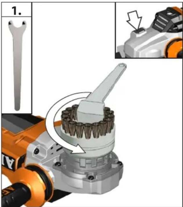

natural_image
Illustration of a wrench, a washer, and a gear-like component (no text or symbols)Accessory
Zubehör
Accessoires
Accessorio
Accessorio
Acessório
Toebehoren
Tilbehør
Tilbehør
Tillbehör
Lisälaite
Εξαρτήματα
Aksesuar
Příslušenství
Príslušenstv
Wyposażenie
Tartozékokat
Oprema
Piederumi
Prieda
Tarvikud
Aksessuaarid
Дополнитель
Аксесоари
Accesoriu
Додатоци
Комплектуючі
الملحق

natural_image
Close-up of a robotic arm with a gear and screw assembly, showing mechanical components (no text or symbols visible)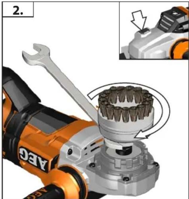
natural_image
Close-up of a robotic arm with a wrench and gear assembly, showing tool path and component details (no text or symbols)
natural_image
Close-up of a robotic arm with a gear assembly and a close-up of its internal components (no text or symbols visible)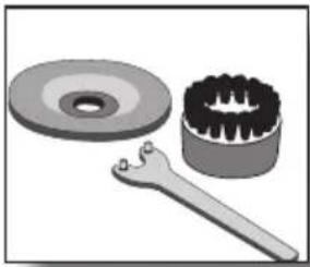
natural_image
Illustration of a mechanical gear assembly including a washer, cutter head, and wrench (no text or symbols)Accessory
Zubehör
Accessoires
Accessorio
Accessorio
Acessório
Toebehoren
Tilbehør
Tilbehør
Tillbehör
Lisälaite
Εξαρτήματα
Aksesuar
Příslušenství
Príslušenstv
Wyposażenie
Tartozékokat
Oprema
Piederumi
Prieda
Tarvikud
Aksessuaarid
Дополнитель
Аксесоари
Accesoriu
Додатоци
Комплектуючі
الملحق

natural_image
Mechanical diagram showing a wrench interacting with a circular component, no text or symbols present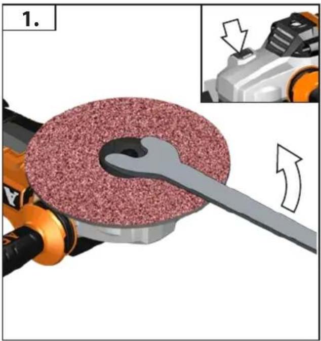
natural_image
Mechanical assembly diagram showing a tool interacting with a textured circular component, with an inset view of a mechanical component (no text or symbols present)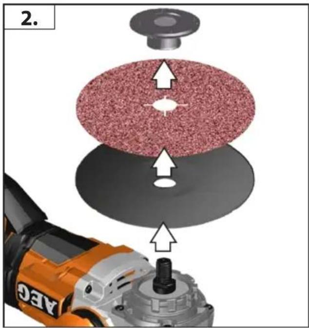
| TECHNICAL DATACordless Angle Grinder | BEWS18-230BL | |
| Production code 4672 50 01 ... | 000001-999999 | |
| Battery voltage 18 V | ||
| Rated speed 5500 min | -1 | |
D= Grinding disk diameter max.d= Grinding disk hole diameter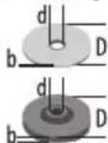 | b= Cutting disk thickness min. / max.b= Grinding disk thickness max. | 230 mm22,2 mm1,9/3 mm8 mm |
 | D= Grinding surface diameter max. 230 mm | |
 | D= Wiring brush diameter max. 100 mm | |
| Thread of work spindle M 14 | ||
| Weight according EPTA-Procedure 01/2014 (Li-Ion 1 x 1,5Ah...2 x 9,0Ah) 5,2 kg ... 7,1 kg | ||
| Recommended Ambient Operating Temperature -18°C ... +50°C | ||
| Recommended battery types L18... | ||
| Recommended charger AL1218... / BL 1218... | ||
| Noise informationMeasured values determined according to EN 60745. Typically, the A-weighted noise levels of the tool are:Sound pressure level (Uncertainty K=3dB(A)) 86,0 dB(A)Sound power level (Uncertainty K=3dB(A))Wear ear protectors! | 97,0 dB(A) | |
| Vibration informationVibration total values (triaxial vector sum) determined according to EN 60745Surface grinding (Li-Ion 1 x 1,5Ah...2 x 9,0Ah): Vibration emission value ah,AGUncertainty K=Disk sanding (Li-Ion 1 x 1,5Ah...2 x 9,0Ah): Vibration emission value ah,DSUncertainty K= | 7,0 m/s21,5 m/s22,5 m/s21,5 m/s2 | |
For other applications, e.g. Abrasive Cutting-Off Operations or Wire Brushing other vibration values could occur.
WARNING!
The vibration emission level given in this information sheet has been measured in accordance with a standardised test given in EN 60745 and may be used to compare one tool with another. It may be used for a preliminary assessment of exposure.
The declared vibration emission level represents the main applications of the tool. However if the tool is used for different applications, with different accessories or poorly maintained, the vibration emission may differ. This may significantly increase the exposure level over the total working period.
An estimation of the level of exposure to vibration should also take into account the times when the tool is switched off or when it is running but not actually doing the job. This may significantly reduce the exposure level over the total working period.
Identify additional safety measures to protect the operator from the effects of vibration such as: maintain the tool and the accessories, keep the hands warm, organisation of work patterns.

WARNING!
Read all safety warnings and all instructions. Failure to follow the warnings and instructions may result in electric shock, fire and/or serious injury.
Save all warnings and instructions for future reference.

ANGLE GRINDER SAFETY WARNINGS
Safety Warnings Common for Grinding, Sanding, Wire Brushing or Abrasive Cutting-Off Operations:
a) This power tool is intended to function as a grinder, sander, wire brush or cut-off tool. Read all safety warnings, instructions, illustrations and specifications provided with
this power tool. Failure to follow all instructions listed below may result in electric shock, fire and/or serious injury.
b) Operations such as polishing are not recommended to be performed with this power tool. Operations for which the power tool was not designed may create a hazard and cause personal injury.
c) Do not use accessories which are not specifically designed and recommended by the tool manufacturer. Just because the accessory can be attached to your power tool, it does not assure safe operation.
d) The rated speed of the accessory must be at least equal to the maximum speed marked on the power tool. Accessories running faster than their rated speed can break and fly apart.
English

e) The outside diameter and the thickness of your accessory must be within the capacity rating of your power tool. Incorrectly sized accessories cannot be adequately guarded or controlled.
f) Threaded mounting of accessories must match the grinder spindle thread. For accessories mounted by flanges, the arbour hole of the accessory must fit the locating diameter of the flange. Accessories that do not match the mounting hardware of the power tool will run out of balance, vibrate excessively and may cause loss of control.
g) Do not use a damaged accessory. Before each use inspect the accessory such as abrasive wheels for chips and cracks, backing pad for cracks, tear or excess wear, wire brush for loose or cracked wires. If power tool or accessory is dropped, inspect for damage or install an undamaged accessory. After inspecting and installing an accessory, position yourself and bystanders away from the plane of the rotating accessory and run the power tool at maximum no-load speed for one minute. Damaged accessories will normally break apart during this test time.
h) Wear personal protective equipment. Depending on application, use face shield, safety goggles or safety glasses. As appropriate, wear dust mask, hearing protectors, gloves and shop apron capable of stopping small abrasive or workpiece fragments. The eye protection must be capable of stopping flying debris generated by various operations. The dust mask or respirator must be capable of filtrating particles generated by your operation. Prolonged exposure to high intensity noise may cause hearing loss.
i) Keep bystanders a safe distance away from work area. Anyone entering the work area must wear personal protective equipment. Fragments of workpiece or of a broken accessory may fly away and cause injury beyond immediate area of operation.
j) Hold the power tool by insulated gripping surfaces only, when performing an operation where the cutting accessory may contact hidden wiring. Cutting accessory contacting a "live" wire may make exposed metal parts of the power tool "live" and could give the operator an electric shock.
k) Never lay the power tool down until the accessory has come to a complete stop. The spinning accessory may grab the surface and pull the power tool out of your control.
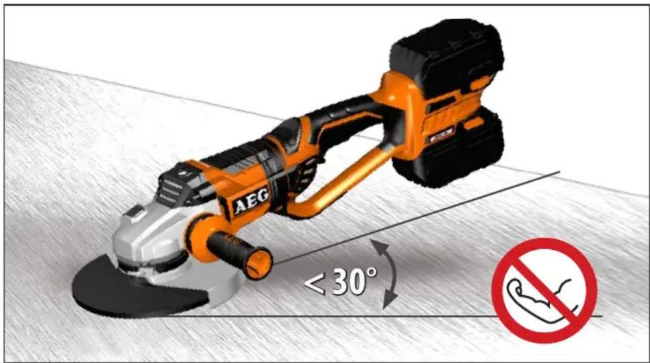
I) Do not run the power tool while carrying it at your side. Accidental contact with the spinning accessory could snag your clothing, pulling the accessory into your body.
m) Regularly clean the power tool's air vents. The motor's fan will draw the dust inside the housing and excessive accumulation of powdered metal may cause electrical hazards.
n) Do not operate the power tool near flammable materials. Sparks could ignite these materials.
o) Do not use accessories that require liquid coolants. Using water or other liquid coolants may result in electrocution or shock.
Kickback and Related Warnings
Kickback is a sudden reaction to a pinched or snagged rotating wheel, backing pad, brush or any other accessory. Pinching or snagging causes rapid stalling of the rotating accessory which in turn causes the uncontrolled power tool to be forced in the direction opposite of the accessory's rotation at the point of the binding. For example, if an abrasive wheel is snagged or pinched by the workpiece, the edge of the wheel that is entering into the pinch point can dig into the surface of the material causing the wheel to climb out or kick out. The wheel may either jump toward or
away from the operator, depending on direction of the wheel's movement at the point of pinching. Abrasive wheels may also break under these conditions.
Kickback is the result of power tool misuse and/or incorrect operating procedures or conditions and can be avoided by taking proper precautions as given below.
a) Maintain a firm grip on the power tool and position your body and arm to allow you to resist kickback forces. Always use auxiliary handle, if provided, for maximum control over kickback or torque reaction during start-up. The operator can control torque reactions or kickback forces, if proper precautions are taken.
b) Never place your hand near the rotating accessory. Accessory may kickback over your hand.
c) Do not position your body in the area where power tool will move if kickback occurs. Kickback will propel the tool in direction opposite to the wheel's movement at the point of snagging.
d) Use special care when working corners, sharp edges etc. Avoid bouncing and snagging the accessory. Corners, sharp edges or bouncing have a tendency to snag the rotating accessory and cause loss of control or kickback.
e) Do not attach a saw chain woodcarving blade or toothed saw blade. Such blades create frequent kickback and loss of control.
Safety Warnings Specific for Grinding and Abrasive Cutting-Off Operations:
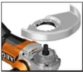
a) Use only wheel types that are recommended for your power tool and the specific guard designed for the selected wheel. Wheels for which the power tool was not designed cannot be adequately guarded and are unsafe.
b) The grinding surface of the centre depressed wheels must be mounted below the plane of the guard lip. An improperly mounted wheel that projects through the plane of the guard lip cannot be adequately protected.
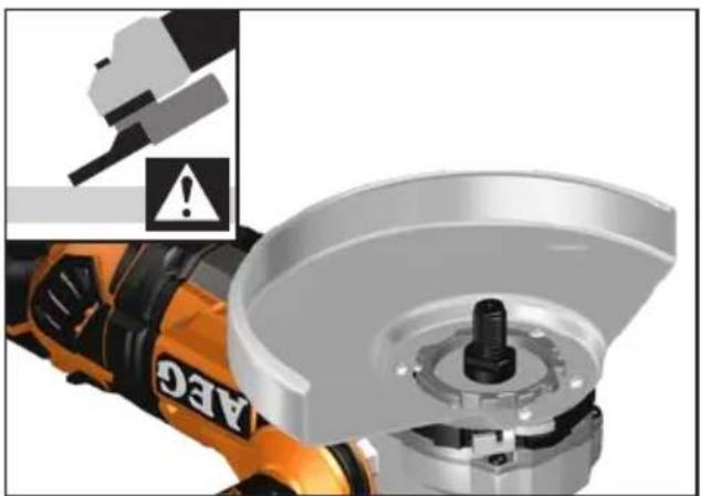
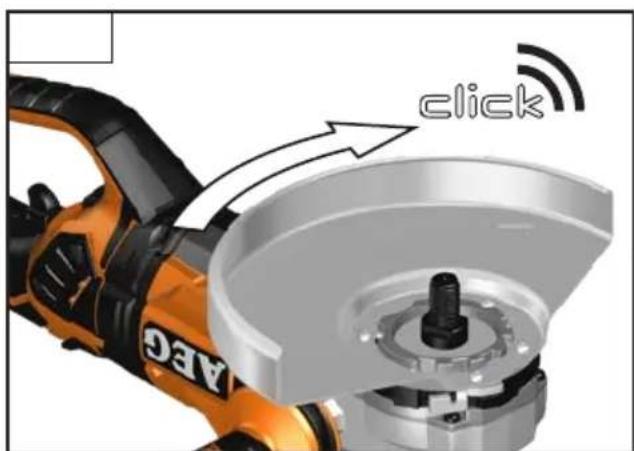
c) The guard must be securely attached to the power tool and positioned for maximum safety, so the least amount of wheel is exposed towards the operator. The guard helps to protect the operator from broken wheel fragments, accidental contact with wheel and sparks that could ignite clothing.
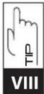
d) Wheels must be used only for recommended applications. For example: do not grind with the side of cut-off wheel.
Abrasive cut-off wheels are intended for peripheral grinding, side forces applied to these wheels may cause them to shatter.
e) Always use undamaged wheel flanges that are of correct size and shape for your selected wheel. Proper wheel flanges support the wheel thus reducing the possibility of wheel breakage. Flanges for cut-off wheels may be different from grinding wheel flanges.
f) Do not use worn down wheels from larger power tools. Wheel intended for larger power tool is not suitable for the higher speed of a smaller tool and may burst.
Additional Safety Warnings Specific for Abrasive Cutting-Off Operations:
a) Do not "jam" the cut-off wheel or apply excessive pressure. Do not attempt to make an excessive depth of cut. Overstressing the wheel increases the loading and susceptibility to twisting or binding of the wheel in the cut and the possibility of kickback or wheel breakage.
English
b) Do not position your body in line with and behind the rotating wheel. When the wheel, at the point of operation, is moving away from your body, the possible kickback may propel the spinning wheel and the power tool directly at you.
c) When wheel is binding or when interrupting a cut for any reason, switch off the power tool and hold the power tool motionless until the wheel comes to a complete stop. Never attempt to remove the cut-off wheel from the cut while the wheel is in motion otherwise kickback may occur. Investigate and take corrective action to eliminate the cause of wheel binding.
d) Do not restart the cutting operation in the workpiece. Let the wheel reach full speed and carefully re-enter the cut. The wheel may bind, walk up or kickback if the power tool is restarted in the workpiece.
e) Support panels or any oversized workpiece to minimize the risk of wheel pinching and kickback. Large workpieces tend to sag under their own weight. Supports must be placed under the workpiece near the line of cut and near the edge of the workpiece on both sides of the wheel.
f) Use extra caution when making a "pocket cut" into existing walls or other blind areas. The protruding wheel may cut gas or water pipes, electrical wiring or objects that can cause kickback.
Safety Warnings Specific for Sanding Operations:
a) Do not use excessively oversized sanding disc paper. Follow manufacturers recommendations, when selecting sanding paper. Larger sanding paper extending beyond the sanding pad presents a laceration hazard and may cause snagging, tearing of the disc or kickback.
Safety Warnings Specific for Wire Brushing Operations:
a) Be aware that wire bristles are thrown by the brush even during ordinary operation. Do not overstress the wires by applying excessive load to the brush. The wire bristles can easily penetrate light clothing and/or skin.
b) If the use of a guard is recommended for wire brushing, do not allow any interference of the wire wheel or brush with the guard. Wire wheel or brush may expand in diameter due to work load and centrifugal forces.
Additional Safety and Working Instructions
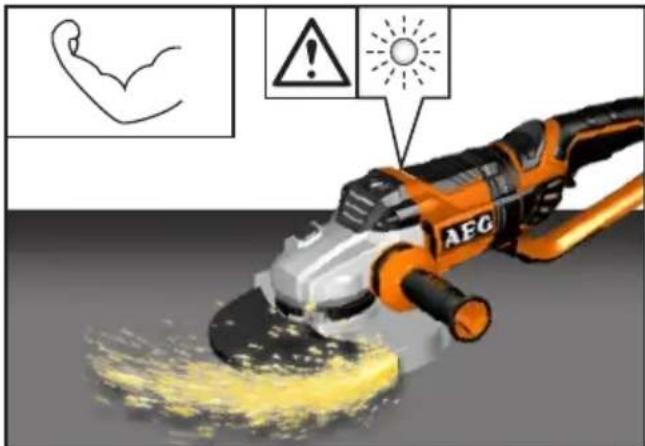
When grinding metal, flying sparks are produced. Take care that no persons are endangered. Because of the danger of fire, no combustible materials should be located in the vicinity (spark flight zone). Do not use dust extraction.
Avoid flying sparks and sanding dust hit your body.
Never reach into the danger area of the machine when it is running.
Chips and splinters must not be removed while the machine is running.
Immediately switch off the machine in case of considerable vibrations or if other malfunctions occur. Check the machine in order to find out the cause.
Under extreme conditions (e.g. smooth-grinding metals with the arbour and vulcanized fibre grinding disk), significant contamination can build up on the inside of the angle grinder.
Do not let any metal parts enter the airing slots - danger of short circuit!
WARNING! To reduce the risk of fire, personal injury, and product damage due to a short circuit, never immerse your tool, battery pack or charger in fluid or al-low a fluid to flow inside them. Corrosive or conductive fluids, such as seawater, certain industrial
chemicals, and bleach or bleach containing products, etc., Can cause a short circuit.
Never break open battery packs and chargers and store only in dry rooms. Keep dry at all times.
Use only System GBS chargers for charging System GBS battery packs. Do not use battery packs from other systems.
SPECIFIED CONDITIONS OF USE
The angle grinder is intended for grinding and cutting metal, stone and ceramic materials as well as sanding and wire brushing.
Use the cutting guard from the accessories range for cutting application.
Please refer to the instructions supplied by the accessory manufacturer.
The machine is suitable only for working without water.
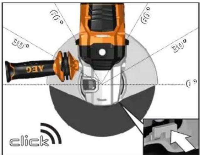
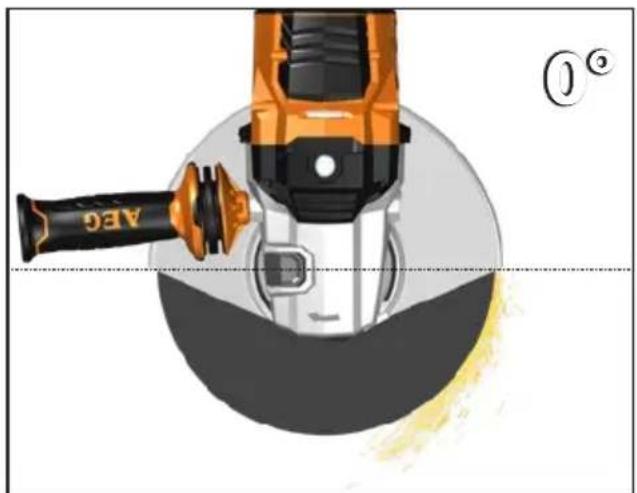
WORKING INSTRUCTIONS
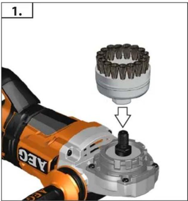
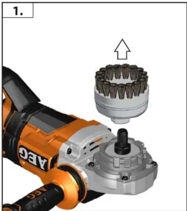
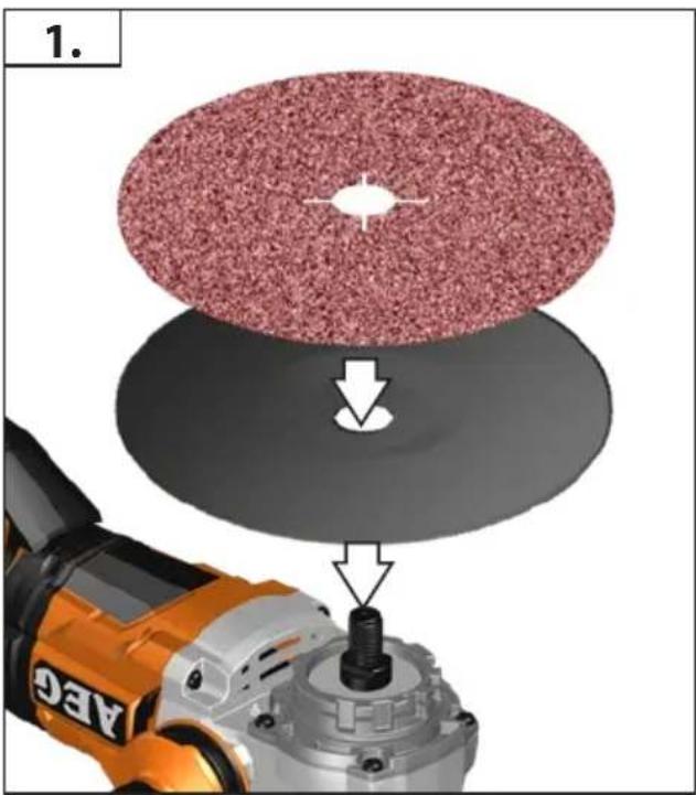
For accessories intended to be fitted with threaded hole wheel, ensure that the thread in the wheel is long enough to accept the spindle length.
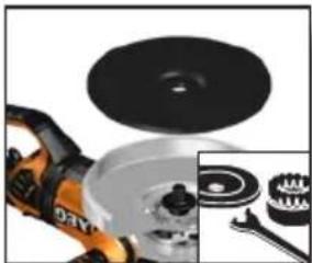
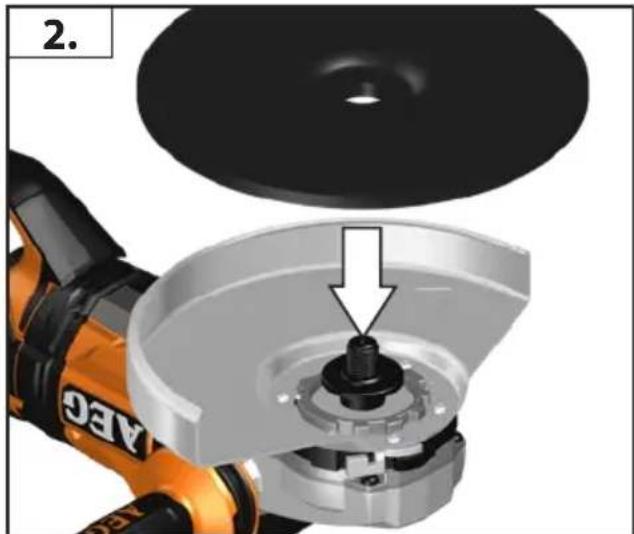
Always use and store the cutting and grinding disks according to the manufacturer's instructions.
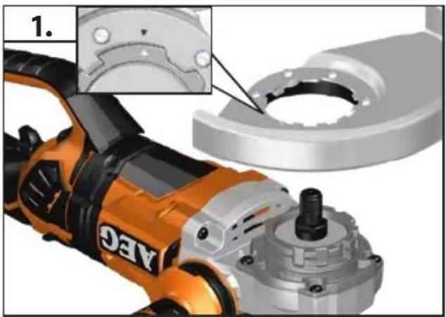
Always use the correct guard for cutting and grinding.
The grinding surface of the centre depressed disks must be mounted min. 2 mm below the plane of the guard lip.
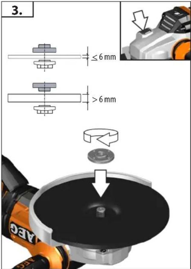
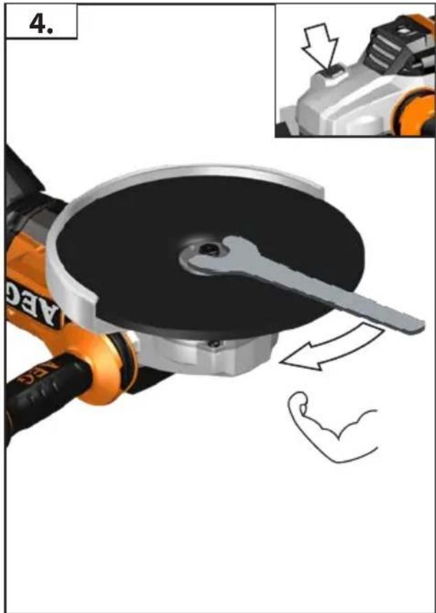
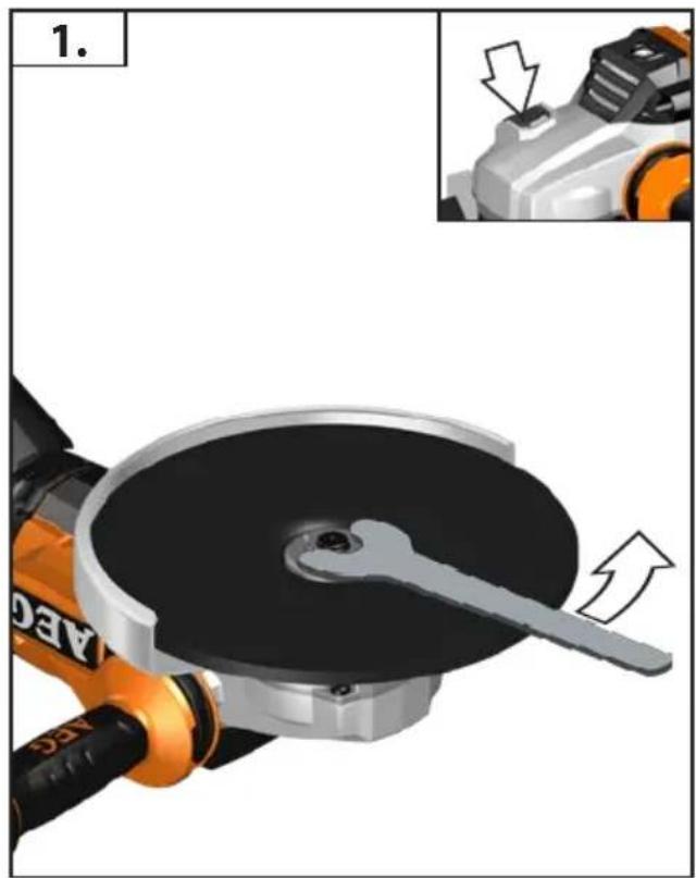
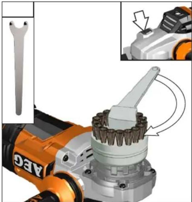
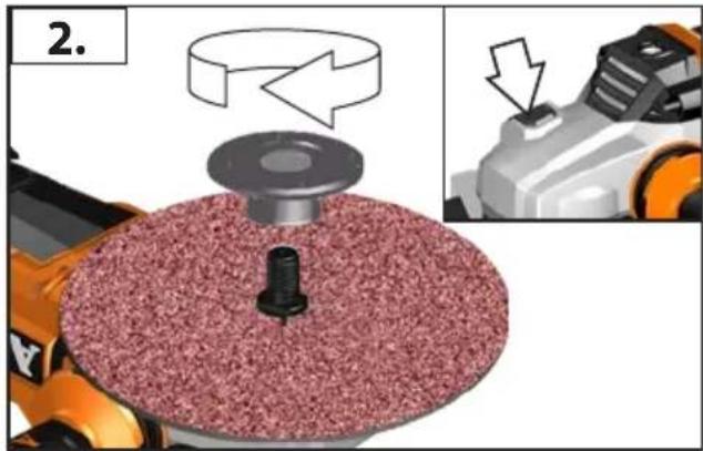
The adjusting nut must be tightened before starting to work with the machine.
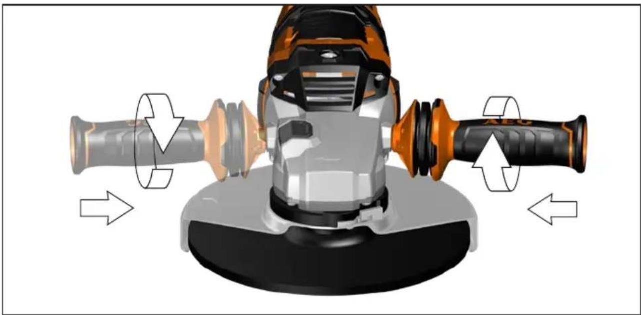
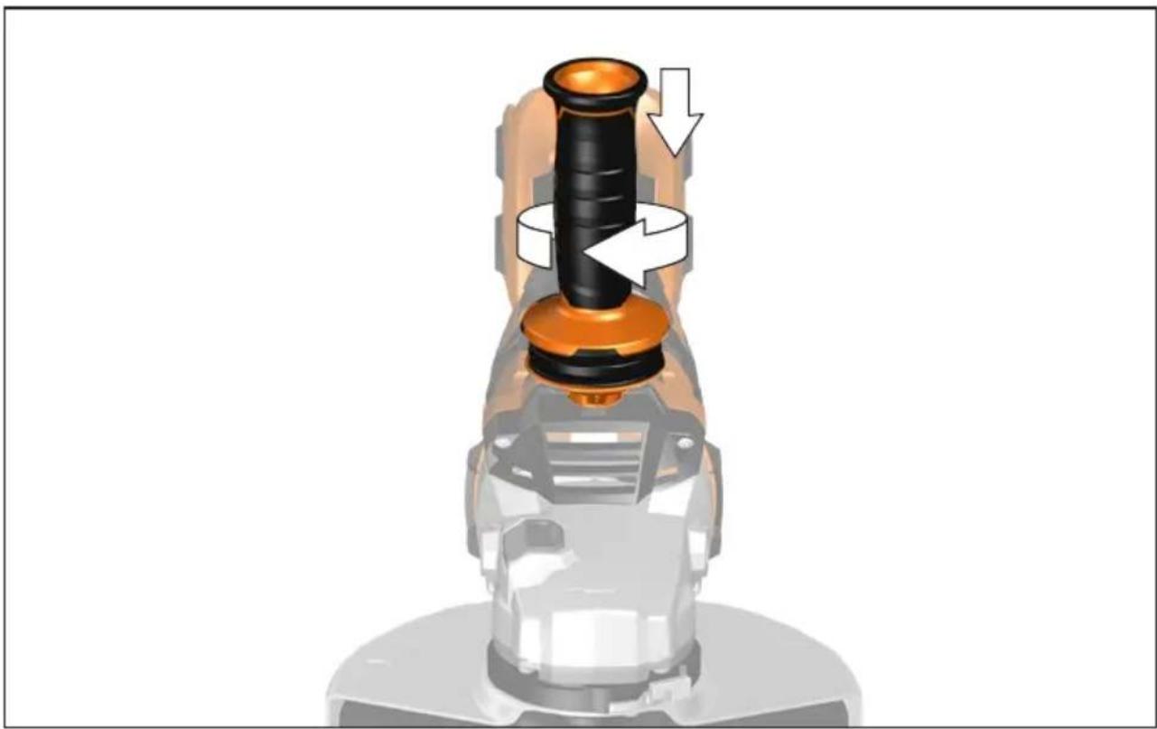
Always use the auxiliary handle.
The workpiece must be fixed if it is not heavy enough to be steady. Never move the workpiece towards the rotating disk by hand.
BATTERIES
Temperatures in excess of 50irc C ( 122irc F) reduce the performance of the battery pack. Avoid extended exposure to heat or sunshine (risk of overheating).
The contacts of chargers and battery packs must be kept clean.
For an optimum life-time, the battery packs have to be fully charged, after use. Battery packs which have not been used for some time should be recharged before use.
To obtain the longest possible battery life remove the battery pack from the charger once it is fully charged.
For battery pack storage longer than 30 days:, Store the battery pack where the temperature is below 27irc C and away from moisture, Store the battery packs in a 30% - 50% charged condition, Every six months of storage, charge the pack as normal.
Do not dispose of used battery packs in the household refuse or by burning them. AEG Distributors offer to retrieve old batteries to protect our environment.
Do not store the battery pack together with metal objects (short circuit risk).
TRANSPORTING LITHIUM BATTERIES
Lithium-ion batteries are subject to the Dangerous Goods Legislation requirements.
Transportation of those batteries has to be done in accordance with local, national and international provisions and regulations.
The user can transport the batteries by road without further requirements.


Commercial transport of Lithium-Ion batteries by third parties is subject to Dangerous Goods regulations. Transport preparation and transport are exclusively to be carried out by appropriately trained persons and the process has to be accompanied by corresponding experts.
When transporting batteries:
Ensure that battery contact terminals are protected and insulated to prevent short circuit. Ensure that battery pack is secured against movement within packaging. Do not transport batteries that are cracked or leak. Check with forwarding company for further advice
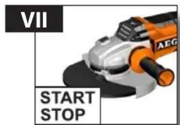
RESTART CUTOUT
A zero-voltage switch prevents the machine from restarting after a power cut (Battery change).
When resuming work, switch the machine off and then switch it back on again.
SMOOTH START
Electronic smooth start for save use prevents jerky run-up of the machine.
MAINTENANCE
Remove the battery pack before starting any work on the appliance.
The ventilation slots of the machine must be kept clear at all times. Use only AEG accessories and spare parts. Should components need to be replaced which have not been described, please contact one of our AEG service agents (see our list of guarantee/service addresses).
If needed, an exploded view of the tool can be ordered. Please state the Article No. as well as the machine type printed on the label and order the drawing at your local service agents or directly at: Techtronic Industries GmbH, Max-Eyth-Straße 10, 71364 Winnenden, Germany.
EC-DECLARATION OF CONFORMITY
We declare under our sole responsibility that the product described under "Technical Data" fulfills all the relevant provisions of the directives
2011/65/EU (RoHS)
2006/42/EC
2014/30/EU
and the following harmonized standards have been used.
EN 60745-1:2009 + A11:2010
EN 60745-2-3:2011 + A2:2013 + A11:2014 + A12:2014 + A13:2015
EN 55014-1:2017
EN 55014-2:2015
EN 50581:2012

Winnenden, 2018-01-30

Alexander Krug / Managing Director
Authorized to compile the technical file
Techtronic Industries GmbH
Max-Eyth-Straße 10, 71364 Winnenden, Germany
SYMBOLS

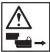
CAUTION! WARNING! DANGER!

Please read the instructions carefully before starting the machine.

Always wear goggles when using the machine.

Wear gloves!

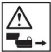
Remove the battery pack before starting any work on the appliance.

ANTI Vibration System

Do not use force.

Only for cutting work.

Only for grinding.

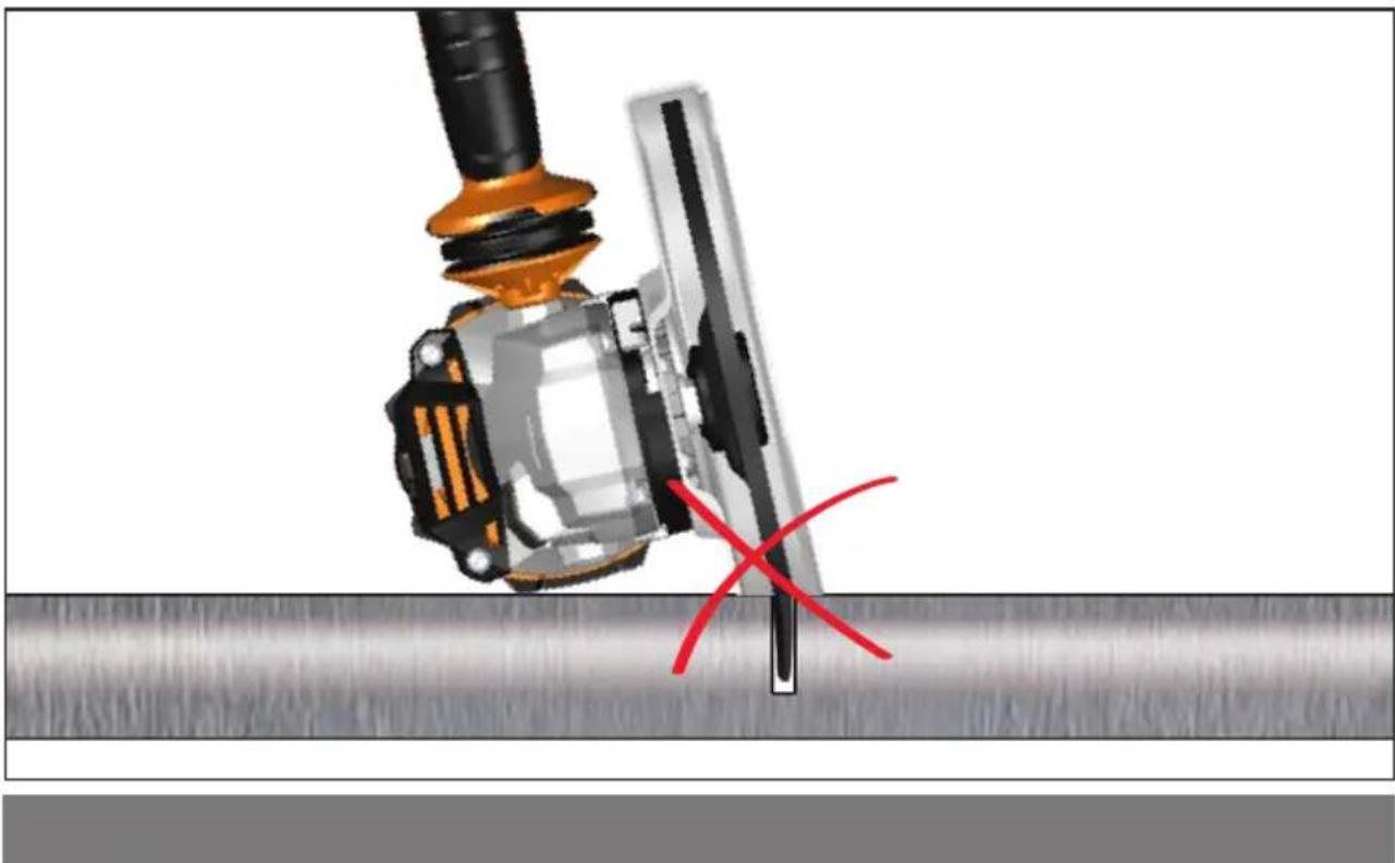
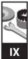
Accessory - Not included in standard equipment, available as an accessory.

Do not dispose electric tools, batteries/rechargeable batteries together with household waste material. Electric tools and batteries that have reached the end of their life must be collected separately and returned to an environmentally compatible recycling facility. Check with your local authority or retailer for recycling advice and collection point.
n
Rated speed

European Conformity Mark

Ukraine Conformity Mark

EurAsian Conformity Mark
English
Alexander Krug / Managing Director
Max-Eyth-Straße 10, 71364 Winnenden, Germany
Deutsch
SYMBOLE

DÉCLARATION CE DE CONFORMITÉ
Alexander Krug / Managing Director
Max-Eyth-Straße 10, 71364 Winnenden, Germany
Français
SYMBOLES

ATTENTION! AVERTISSEMENT! DANGER!

Alexander Krug / Managing Director
Max-Eyth-Straße 10, 71364 Winnenden, Germany
SIMBOLI

ATTENZIONE! AVVERTENZA! PERICOLO!

Alexander Krug / Managing Director
Max-Eyth-Straße 10, 71364 Winnenden, Germany
SÍMBOLOS

Alexander Krug / Managing Director
Max-Eyth-Straße 10, 71364 Winnenden, Germany
Português
SYMBOLE

ATENÇÃO! PERIGO!

Alexander Krug / Managing Director
Max-Eyth-Straße 10, 71364 Winnenden, Germany

SYMBOLEN

OPGELET! WAARSCHUWING! GEVAAR!

Alexander Krug / Managing Director
Max-Eyth-Straße 10, 71364 Winnenden, Germany
Dansk
SYMBOLER

VIGTIGT! ADVARSEL! FARE!

Alexander Krug / Managing Director
Max-Eyth-Straße 10, 71364 Winnenden, Germany
SYMBOLER

OBS! ADVARSEL! FARE!

Alexander Krug / Managing Director
Max-Eyth-Straße 10, 71364 Winnenden, Germany

SYMBOLER

OBSERVERA! WARNING! FARA!

Läs instruktionen noga innan du startar maskinen.

Alexander Krug / Managing Director
Max-Eyth-Straße 10, 71364 Winnenden, Germany
Suomi
SYMBOLIT

HUOMIO! VAROITUS! VAARA!

Alexander Krug / Managing Director
Max-Eyth-Straße 10, 71364 Winnenden, Germany
ΣΥΜΒΟΛΑ

Alexander Krug / Managing Director
Max-Eyth-Straße 10, 71364 Winnenden, Germany
SEMBOLLER

DİKKAT! UYARI! TEHLİKE!

Alexander Krug / Managing Director
Max-Eyth-Straße 10, 71364 Winnenden, Germany

SYMBOLY

POZOR! VAROVÁN! NEBEZPEČÍ!

CE - VYHLÁSENIE KONFORMITY
Max-Eyth-Straße 10, 71364 Winnenden, Germany
Slovensky
SYMBOLY

POZOR! NEBEZPEČENSTVO!

Alexander Krug / Managing Director
Max-Eyth-Straße 10, 71364 Winnenden, Germany
SYMBOLE

Alexander Krug / Managing Director
Max-Eyth-Straße 10, 71364 Winnenden, Germany
Magyar
SZIMBÓLUMOK

FIGYELEM! FIGYELMEZTETÉS! VESZÉLY!

UPORABA V SKLADU Z NAMEMBNOSTJO
Alexander Krug / Managing Director
Max-Eyth-Straße 10, 71364 Winnenden, Germany

SIMBOLI

POZOR! OPOZORILO! NEVARNO!

Prosimo, da pred uporabo pozorno preberete to navodilo za uporabo.

Alexander Krug / Managing Director
Ovlašten za formiranje tehničke dokumentacije.
Techtronic Industries GmbH
Max-Eyth-Straße 10, 71364 Winnenden, Germany
SIMBOLI

PAŽNJA! UPOZORENIE! OPASNOST!

Molimo da pažljivo pročitate uputu o upotrebi prije puštanja u rad.

Alexander Krug / Managing Director
Max-Eyth-Straße 10, 71364 Winnenden, Germany

SIMBOLI


UZMANİBU! BİSTAMI!

Max-Eyth-Straße 10, 71364 Winnenden, Germany
SIMBOLIAI

DĖMESIO! JSPĖJIMAS! PAVOJUS!

Alexander Krug / Managing Director
Max-Eyth-Straße 10, 71364 Winnenden, Germany
SÜMBOLID

ETTEVAATUST! TÄHELEPANU! OHUD!

Alexander Krug / Managing Director
Max-Eyth-Straße 10, 71364 Winnenden, Germany
СИМВОЛЫ

Alexander Krug / Managing Director
Max-Eyth-Straße 10, 71364 Winnenden, Germany
СИМВОЛИ

Alexander Krug / Managing Director
Max-Eyth-Straße 10, 71364 Winnenden, Germany
Romănia
SIMBOLURI

PERICOL! AVERTIZARE! ATENTIE!

Max-Eyth-Straße 10, 71364 Winnenden, Germany
СИМБОЛИ

ВНИМАНИЕ! ПРЕДУПРЕДУВАНЬЕ! ОПАСНОСТ!

Alexander Krug / Managing Director
Max-Eyth-Straße 10, 71364 Winnenden, Germany
СИМВОЛИ


- WARNING!
- ANGLE GRINDER SAFETY WARNINGS
- Kickback and Related Warnings
- English
- Safety Warnings Specific for Sanding Operations:
- Safety Warnings Specific for Wire Brushing Operations:
- Additional Safety and Working Instructions
- SPECIFIED CONDITIONS OF USE
- WORKING INSTRUCTIONS
- BATTERIES
- TRANSPORTING LITHIUM BATTERIES
- RESTART CUTOUT
- SMOOTH START
- MAINTENANCE
- EC-DECLARATION OF CONFORMITY
- SYMBOLS
- Deutsch
- SYMBOLE
- DÉCLARATION CE DE CONFORMITÉ
- SYMBOLES
- SIMBOLI
- SÍMBOLOS
- Português
- SYMBOLEN
- Dansk
- SYMBOLER
- Suomi
- SYMBOLIT
- ΣΥΜΒΟΛΑ
- SEMBOLLER
- SYMBOLY
- CE - VYHLÁSENIE KONFORMITY
- Slovensky
- Magyar
- SZIMBÓLUMOK
- UPORABA V SKLADU Z NAMEMBNOSTJO
- SIMBOLIAI
- SÜMBOLID
- СИМВОЛЫ
- СИМВОЛИ
- Romănia
- SIMBOLURI
- СИМБОЛИ
Brand : AEG
Model : BEWS 18-230BL
Category : Grinder