U14ME1E8E - Air-conditioner PANASONIC - Free user manual and instructions
Find the device manual for free U14ME1E8E PANASONIC in PDF.
Download the instructions for your Air-conditioner in PDF format for free! Find your manual U14ME1E8E - PANASONIC and take your electronic device back in hand. On this page are published all the documents necessary for the use of your device. U14ME1E8E by PANASONIC.
USER MANUAL U14ME1E8E PANASONIC
- We recommend that this air conditioner be installed properly by qualified installation technicians in accordance with the Installation Instructions provided with the unit.
- Before installation, check that the voltage of the electric supply in your home or office is the same as the voltage shown on the nameplate. Electrical Requirements
1. All wiring must conform to the local electrical codes. Consult your dealer or a qualified
electrician for details.
2. Each unit must be properly grounded with a ground (or earth) wire or through the supply
3. Wiring must be done by a qualified electrician.
- Read this Instruction Manual carefully before using this air conditioner. If you still have any difficulties or problems, consult your dealer for help.
- This air conditioner is designed to give you comfortable room conditions. Use this only for its intended purpose as described in this Instruction Manual.
- Do not install this air conditioner where there are fumes or flammable gases, or in an extremely humid space such as a greenhouse.
- Do not install the air conditioner where excessively high heat-generating objects are placed. Avoid: To protect the air conditioner from heavy corrosion, avoid installing the outdoor unit where salty sea water can splash directly onto it or in sulphurous air near a spa. To warm up the system, the power mains must be turned on at least five (5) hours before operation. Leave the power mains ON unless you will not be using this appliance for an extended period.
- Never touch the unit with wet hands.
- Never use or store gasoline or other flammable vapor or liquid near the air conditioner — it is very dangerous.
- This air conditioner has no ventilator for intaking fresh air from outdoors. You must open doors or windows frequently when you use gas or oil heating appliances in the same room, which consume a lot of oxygen from the air. Otherwise there is a risk of suffocation in an extreme case.
- Provide a power outlet to be used exclusively for each unit, and a power supply disconnect, circuit breaker and earth leakage breaker for overcurrent protection should be provided in the exclusive line.
- Provide a power outlet exclusively for each unit, and full disconnection means having a contact separation in all poles must be incorporated in the fixed wiring in accordance with the wiring rules.
- To prevent possible hazards from insulation failure, the unit must be grounded.
- Do not clean inside the indoor and outdoor units by users. Engage authorized dealer or specialist for cleaning.
- In case of malfunction of this appliance, do not repair by yourself. Contact to the sales dealer or service dealer for a repair.
- Refrigerant gas leakage may cause fire.
- For safety, be sure to turn the air conditioner off and also to disconnect the power before cleaning or servicing.
- Stop using the product when any abnormality/failure occurs and disconnect the power plug or turn off the power switch and breaker. (Risk of smoke/ fire/electric shock) Power mains
OI-070-3-EN 01_85464609070013_EN.fm Page 3 Thursday, February 3, 2011 3:19 PM4
- Do not turn the air conditioner on and off from the power mains switch. Use the ON/ OFF operation button.
- Do not stick anything into the air outlet of the outdoor unit. This is dangerous because the fan is rotating at high speed.
- Do not touch the air inlet or the sharp aluminum fins of the outdoor unit. You may get hurt.
- Keep the fire alarm and the air outlet at least 1.5m away from the unit.
- This appliance is not intended for use by persons(including children) with reduced physical, sensory or mental capabilities, or lack of experience and knowledge, unless they have been given supervision or instruction concerning use of the appliance by a person responsible for their safety. Children should be supervised to ensure that do not play with the appliance.
- Do not cool or heat the room too much if babies or invalids are present.
- Do not sit or step on the unit. You may fall down accidentally.
- Do not stick any object into the FAN CASE. You may be injured and the unit may be damaged.
- The compressor may occasionally stop during thunderstorms. This is not a mechanical failure. The unit automatically recovers after a few minutes.
- The English text is the original instructions. Other languages are translation of the original instructions. NOTICE OI-070-4-EN 01_85464609070013_EN.fm Page 4 Thursday, February 3, 2011 3:19 PM5 Wireless Remote Control Unit (Optional parts) Timer Remote Control Unit (Optional parts) Operation Condition Refer to the Instruction Manual attached to the optional Wireless Remote Control Unit. Refer to the Instruction Manual attached to the optional Timer Remote Control Unit. Use this air conditioner under the following temperature range. Indoor temperature range: Cooling mode 14°C-25°C (*WBT) Heating mode 15°C-30°C (*DBT) Outdoor temperature range: Cooling mode -10°C-43°C (*DBT) Heating mode -25°C-15°C (*WBT) 3WAY
-25°C-20°C (*WBT) 2WAY
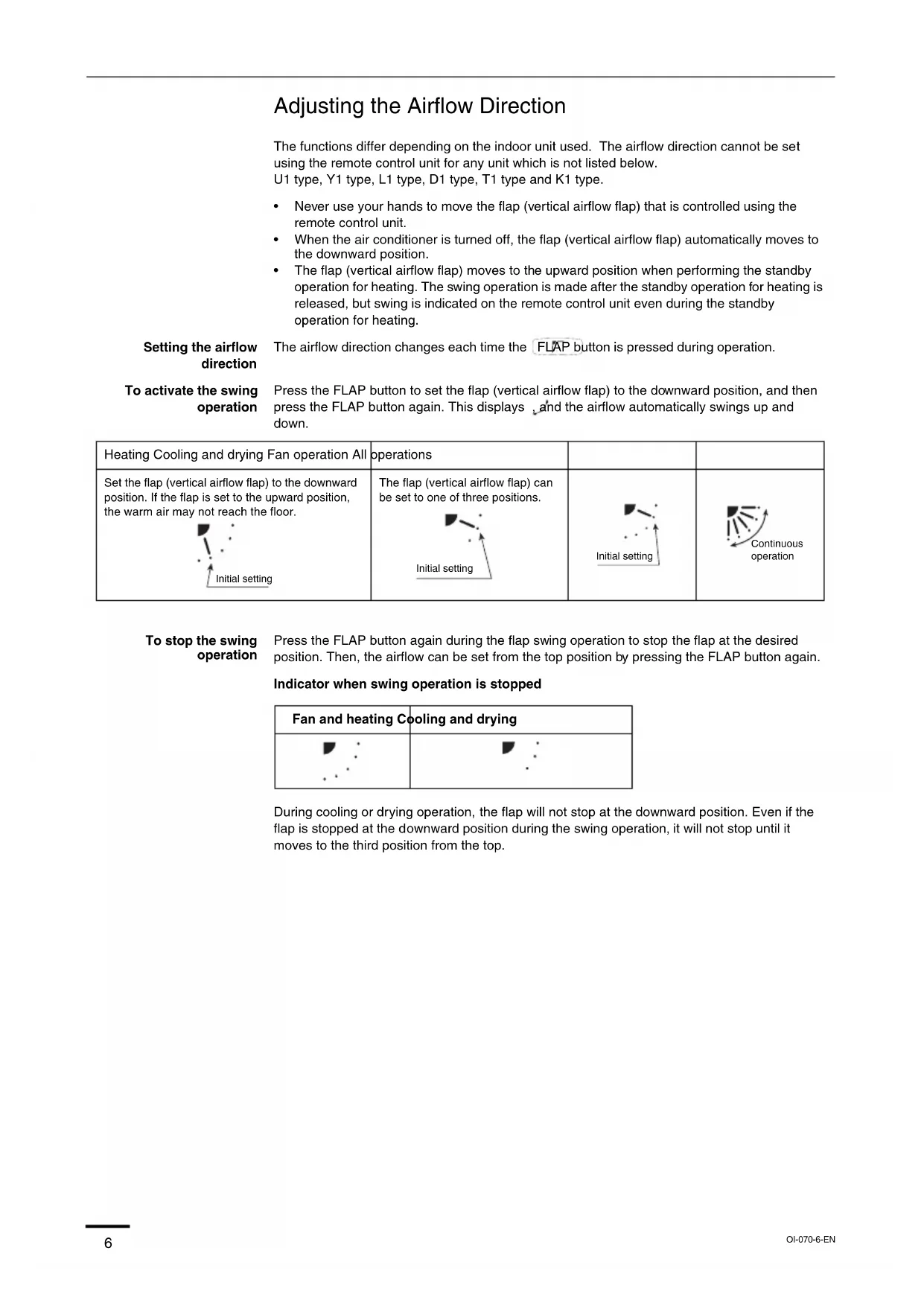
*DBT: Dry bulb temperature *WBT: Wet bulb temperature NOTE NOTE OI-070-5-EN 01_85464609070013_EN.fm Page 5 Thursday, February 3, 2011 3:19 PM6 Adjusting the Airflow Direction The functions differ depending on the indoor unit used. The airflow direction cannot be set using the remote control unit for any unit which is not listed below. U1 type, Y1 type, L1 type, D1 type, T1 type and K1 type.
- Never use your hands to move the flap (vertical airflow flap) that is controlled using the remote control unit.
- When the air conditioner is turned off, the flap (vertical airflow flap) automatically moves to the downward position.
- The flap (vertical airflow flap) moves to the upward position when performing the standby operation for heating. The swing operation is made after the standby operation for heating is released, but swing is indicated on the remote control unit even during the standby operation for heating. Setting the airflow direction The airflow direction changes each time the FLAP button is pressed during operation. To activate the swing operation Press the FLAP button to set the flap (vertical airflow flap) to the downward position, and then press the FLAP button again. This displays , and the airflow automatically swings up and down. To stop the swing operation Press the FLAP button again during the flap swing operation to stop the flap at the desired position. Then, the airflow can be set from the top position by pressing the FLAP button again. Indicator when swing operation is stopped During cooling or drying operation, the flap will not stop at the downward position. Even if the flap is stopped at the downward position during the swing operation, it will not stop until it moves to the third position from the top. Heating Cooling and drying Fan operation All operations Set the flap (vertical airflow flap) to the downward position. If the flap is set to the upward position, the warm air may not reach the floor. The flap (vertical airflow flap) can be set to one of three positions. Initial setting Initial setting Initial setting Continuous operation Fan and heating Cooling and drying OI-070-6-EN 01_85464609070013_EN.fm Page 6 Thursday, February 3, 2011 3:19 PM7 Adjusting the Airflow Direction (continued) U1 type, Y1 type, L1 type and D1 type air conditioners are equipped with auto flaps. You can set the airflow direction to a specific angle or to the sweep mode using the remote control unit. Do not move the flap with your hands. 4-way (U1 type), (Y1 type) • The air outlet flap can be easily removed and washed with water.
- Be sure to always stop operation before removing the flap.
- After washing with water, allow it to dry, and then remount it with the arrow facing outward. Ceiling mounted type (T1) Vertical directions (automatic) This air conditioner is equipped with an auto flap. You can set the airflow direction to a specific angle or to the sweep mode using the remote control unit. (Refer to the description of the remote control unit.) Do not move the flap with your hands. Horizontal directions (manual) The horizontal airflow direction can be adjusted manually by moving the vertical vanes to the left or right. Wall mounted type (K1) Vertical directions (automatic) Confirm that the remote control unit has been turned on. Press the FLAP button to start the flap moving up and down. If you want to stop the flap movement and to direct the air in the desired direction, press the FLAP button again. In the cool mode, do not direct the flap down and move out of the cooling zone “A”, otherwise, condensation may drip on to the floor. Zone ‘‘A’’ is the recommended flap position for cooling. When operating continuously in the fixed airflow direction setting for about an hour, the airflow direction is automatically controlled and the flap position is changed. The airflow direction may be different from the display on the remote controller. Do not move the flap with your hands. Horizontal directions (manual) The horizontal airflow direction can be adjusted manually by moving the vertical vanes to the left or right. Concealed duct type (F1, M1, E1) This air conditioner is not equipped with air outlet parts. These must be obtained locally. Please refer to the manual of the locally adopted air outlet parts. Indoor unit Zone ‘‘B’’ for heating Zone ‘‘A’’ for cooling OI-070-7-EN 01_85464609070013_EN.fm Page 7 Thursday, February 3, 2011 3:19 PM8 Adjusting the Airflow Direction for Multiple Indoor Units Using a Single Remote Control Unit (Wired)
- The airflow direction cannot be set using the remote control unit for the concealed duct type (F1, M1, E1) and floor standing type (P1, R1).
- If multiple indoor units are connected to a remote control unit, the airflow direction can be set for each indoor unit by selecting the indoor units (see the operation below). Auto Flap ( ) button
- To set the airflow for individual units, press the UNIT button. Display shows the indoor unit number under group control. Set the airflow direction for the indoor unit that is shown on the display.
- Each time UNIT is pressed, the indicator changes in the order shown below.
- When nothing is displayed, you can make the setting for all indoor units in one operation.
- The unit number is displayed as Outdoor Unit Number–Indoor Unit Number. It varies depending on the number of units under group control. One outdoor unit and eight indoor units Two outdoor units and four indoor units No display Unit No. 1–1 Unit No. 1–2 Unit No. 1–3 Unit No. 1–8
display Unit No. 1–1 Unit No. 1–2 Unit No. 1–3 Unit No. 2–4 Unit No. 1–4 Unit No. 2–1 OI-070-8-EN 01_85464609070013_EN.fm Page 8 Thursday, February 3, 2011 3:19 PM9 Special Remarks Care and Cleaning How it works • Once the room temperature reaches the level that was set, the unit repeats the cycle of turning on and off automatically.
- In order to prevent the humidity in the room from rising again, the indoor fan also turns off when the unit stops operating.
- The fan speed is set to ‘‘LO.’’ automatically, and cannot be adjusted.
- ‘‘DRY’’ operation is not possible if the outdoor temperature is 15 °C or less. Heating performance • Because this appliance heats a room by utilizing the heat of the outside air (heat pump system), the heating efficiency will fall off when the outdoor temperature is very low. If sufficient heat cannot be obtained with this heat pump, use another heating appliance in conjunction with this unit. Defrosting • When the outdoor temperature is low, frost or ice may form on the outdoor heat exchanger coil, reducing the heating performance. When this happens, a microcomputer-controlled defrosting system operates. At the same time, the fan on the indoor unit stops (or runs at very low speed in some cases) and the ‘‘STANDBY’’ indicator appears on the display until defrosting is completed. Heating operation then restarts after several minutes. (This interval will vary slightly depending upon the outdoor temperature and the way in which frost forms.) (standby) on the display
- For several minutes after the start of heating operation, the indoor fan will not start running (or it will run at very low speed in some cases) until the indoor heat exchanger coil has warmed up sufficiently. This is because a cold draft prevention system is operating. During this period, the ‘‘ ’’ (standby) indicator remains displayed.
- ‘‘ ’’ (standby) remains displayed during defrosting or when the compressor has been turned off (or when the unit is running at very low speed) by the thermostat when the system is in the heating mode.
- Upon completion of defrosting and when the compressor is turned on again, ‘‘ ’’ (standby) will turn off automatically as heating operation resumes. Should the power fail while the unit is running If the power supply for this unit is temporarily cut off, the unit will automatically resume operation (once the power is restored) using the same settings before the power was cut off.
1. For safety, be sure to turn the air conditioner off and also to disconnect the power
2. Do not pour water on the indoor unit to clean it. This will damage the internal
components and cause an electric shock hazard. Air intake and outlet side (Indoor unit) Clean the air intake and outlet side of the indoor unit with a vacuum cleaner brush, or wipe them with a clean, soft cloth. If these parts are stained, use a clean cloth moistened with water. When cleaning the air outlet side, be careful not to force the vanes out of place.
1. Never use solvents or harsh chemicals when cleaning the indoor unit. Do not wipe
plastic parts using very hot water.
2. Some metal edges and the fins are sharp and may cause injury if handled
improperly; be especially careful when you clean these parts.
3. The internal coil and other components of the outdoor unit must be cleaned
periodically. Consult your dealer or service center. ‘‘DRY’’ Operation Heating Operation NOTE OI-070-9-EN 01_85464609070013_EN.fm Page 9 Thursday, February 3, 2011 3:19 PM10 Safety Instructions Stop using the product when any abnormality/failure occurs and disconnect the power plug. (Risk of smoke/fire/electric shock) Examples of abnormality/failure- The product sometimes does not start when turned on.- The power is sometimes disconnected when the cord is moved.- Burnt odor or abnormal noise is detected during operation.- The body is deformed or abnormally hot. Contact immediately your local dealer for maintenance/repair. Information for Users on Collection and Disposal of Old Equipment and Used Batteries These symbols on the products, packaging, and/or accompanying documents mean that used electrical and electronic products and batteries should not be mixed with general household waste. For proper treatment, recovery and recycling of old products and used batteries, please take them to applicable collection points, in accordance with your national legislation and the Directives 2002/96/EC and 2006/66/EC. By disposing of these products and batteries correctly, you will help to save valuable resources and prevent any potential negative effects on human health and the environment which could otherwise arise from inappropriate waste handling. For more information about collection and recycling of old products and batteries, please contact your local municipality, your waste disposal service or the point of sale where you purchased the items. Penalties may be applicable for incorrect disposal of this waste, in accordance with national legislation. For business users in the European Union If you wish to discard electrical and electronic equipment, please contact your dealer or supplier for further information. [Information on Disposal in other Countries outside the European Union] These symbols are only valid in the European Union. If you wish to discard these items, please contact your local authorities or dealer and ask for the correct method of disposal. Note for the battery symbol (bottom two symbol examples): This symbol might be used in combination with a chemical symbol. In this case it complies with the requirement set by the Directive for the chemical involved.
OI-070-3-FR 02_85464609070013_FR.fm Page 13 Thursday, February 3, 2011 3:20 PM14
tromversorgung EIN OI-070-3-DE 03_85464609070013_DE.fm Page 23 Thursday, February 3, 2011 3:21 PM24
OI-070-3-IT 04_85464609070013_IT.fm Page 33 Thursday, February 3, 2011 3:21 PM34
OI-070-3-PT 05_85464609070013_PT.fm Page 43 Thursday, February 3, 2011 3:22 PM44
OI-070-3-GR 06_85464609070013_GR.fm Page 53 Thursday, February 3, 2011 3:34 PM54
(encendido) OI-070-3-ES 07_85464609070013_ES.fm Page 63 Thursday, February 3, 2011 3:22 PM64
BTU/h Heating Capacity
7,500 9,600 12,000 15,000
BTU/h Heating Capacity
BTU/h Heating Capacity
14,000 17,000 21,000 27,000
12,000 15,000 19,000 25,000
210×910×680 210×910×680 210×1180×680 210×1595×680 210×1595×680 08_85464609070013_Spec.fm Page 71 Thursday, February 3, 2011 3:23 PM72 High Static Pressure Ducted (E1 type) Power Source 220 - 230 - 240 V, single-phase, 50/60 Hz
BTU/h Heating Capacity
27,000 39,000 54,600 85,300
BTU/h Heating Capacity
BTU/h Heating Capacity
7,500 9,600 12,000 15,000
BTU/h Heating Capacity
7,500 9,600 12,000 15,000
BTU/h Heating Capacity
7,500 9,600 12,000 15,000
BTU/h Heating Capacity
BTU/h Heating Capacity
9,600 12,000 15,000 19,000
Floor Standing (P1 type) Net Weight
BTU/h Heating Capacity
7,500 9,600 12,000 15,000
BTU/h Heating Capacity
7,500 9,600 12,000 15,000
616×1219×229 08_85464609070013_Spec.fm Page 74 Thursday, February 3, 2011 3:23 PM75 Wall Mounted (K1 type) Power Source 220 - 230 - 240 V, single-phase, 50/60 Hz Model Name S-22MK1E5 S-28MK1E5 S-36MK1E5 Sound Pressure Level High Medium Cooling Capacity
BTU/h Heating Capacity
BTU/h Heating Capacity
BTU/h Heating Capacity
BTU/h Heating Capacity
2WAY (ME1 series) High-COP mode Power Source Model Name U-8ME1E8 Sound Pressure Level Cooling Capacity
BTU/h Heating Capacity
- Outdoor unit model name ended with letters "E8E" is salt-air damage resistant specifications.
- Outdoor unit model name ended with letters "E8E" is salt-air damage resistant specifications. 08_85464609070013_Spec.fm Page 76 Thursday, February 3, 2011 3:23 PM77 3WAY (MF1 series) Power Source Model Name U-8MF1E8 U-10MF1E8 U-12MF1E8 U-14MF1E8 U-16MF1E8 Sound Pressure Level Cooling Capacity
BTU/h Heating Capacity