
AC5517CH - Air-conditioner TRISTAR - Free user manual and instructions
Find the device manual for free AC5517CH TRISTAR in PDF.
| Brand | TriStar |
| Model | AC5517CH |
| Product type | Portable air conditioner |
| Power supply | 220-240 V ~ 50 Hz |
| Operating modes | Cooling, Ventilation, Dehumidification |
| Set temperature range (cooling) | 17-30 °C |
| Operating ambient temperature range | 10-35 °C |
| Fan speeds | High, Low |
| Built-in timer | Yes, programmable (delayed start/stop) |
| Remote control included | Yes |
| Air filter | Washable, cleaning every 2 weeks recommended |
| Condensate management | Internal tank with full indicator; manual or continuous drainage possible |
| Heat exhaust hose length | 280-1500 mm |
| Minimum distance from walls/obstacles | ≥ 50 cm |
| Safety | Automatic shutdown when tank full, anti-freeze protection, compressor overheating protection |
| Display | Dual display 88 with LED indicators |
| Warranty | 24 months |
Frequently Asked Questions - AC5517CH TRISTAR
User questions about AC5517CH TRISTAR
0 question about this device. Answer the ones you know or ask your own.
Ask a new question about this device
Download the instructions for your Air-conditioner in PDF format for free! Find your manual AC5517CH - TRISTAR and take your electronic device back in hand. On this page are published all the documents necessary for the use of your device. AC5517CH by TRISTAR.
USER MANUAL AC5517CH TRISTAR
natural_image
White portable air conditioner with black ventilation slots and a visible brand logo (no text or symbols on the device body)EN | Instruction manual
NL | Gebruiksaanwijzing
FR | Mode d'emploi
DE| Bedieningsanleitung
ES | Manual de usuario
PT | Manual de utilizador
IT | Manuele utente
SV | Bruksanvisning
PL | Instrukcja obsługi
CS | Návod na použití
SK | Návod na použitie


\*\*\* TRISTAR
FIGURES / AFBEELDINGEN / FIGURES / ABB. / FIGURA / RYSUNEK / BILD / OBRÁZEK / OBRÁZOK
flowchart
graph TD
    A["Component 1"] -->|1A| B["Component 2A"]
    C["Component 1"] -->|1| D["Component 2"]
natural_image
Technical line drawings of two air conditioning machines labeled Figure 5 and Figure 6, showing internal components and wiring (no text or symbols on the devices themselves)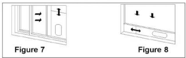
natural_image
Line drawing of a portable air conditioner unit inside a room, with dimension lines indicating 500x height (no text or symbols on the device itself)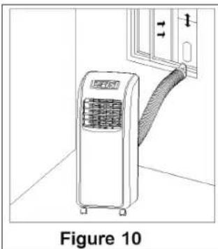
natural_image
Line drawing of an air conditioner unit with a curved arm, labeled Figure 10 (no text or symbols on the device itself)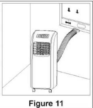
natural_image
Line drawing of an air conditioner unit with a hose, labeled Figure 11 (no text or symbols on the device itself)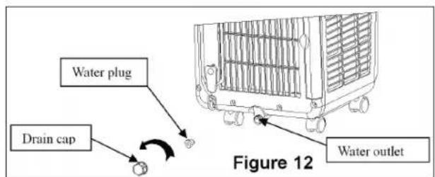
natural_image
Technical line drawings of two air conditioning units labeled Figure 15 and Figure 16, showing internal fan structures (no text or symbols on the devices themselves)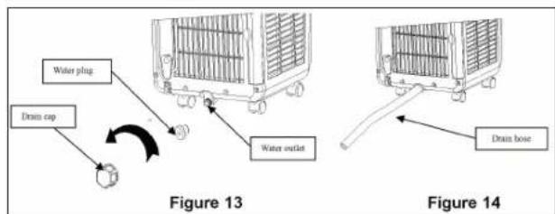
\*\*\* TRISTAR Instruction manual
IMPORTANT SAFEGUARDS
- This air-conditioner is suitable for indoor use only rather than for other occasions.
- Rated operating range: this unit shall be connected to 220-240V / 50Hz power output end.
- The air-conditioner shall be installed in accordance with the wiring rules of local grid to ensure proper grounding. Should you have any question about electrical installation, follow the User's Manual or have the installation done by professional electrician whenever necessary.
- Please put this unit in a flat and dry place and keep it at least 50cm away from surrounding objects or walls.
- Once the air-conditioner is installed, ensure that the plug wire is in good condition and inserted firmly into the power socket and always ensure that the power cord is arranged in order to prevent the personnel from stumbling over it or the plug from being pulled out.
- Do not insert any object into the air inlet/outlet of the air-conditioner. Be sure to keep the air inlet/outlet of the air-conditioner unblocked.
- Where there is the need to install a drain pipe, ensure that the connection of the drain pipe is in good condition without flexure.
- When adjusting the horizontal/vertical louver at the air outlet, turn it slightly by hand to avoid damage of the louver.
-
Keep the unit in an upright position when moving it.
-
Keep this unit away from gasoline, flammable gases, oven or other heat sources.
- Do not dismantle, inspect or modify the unit without authorization as this may result in fault of the unit, and even bodily injury & property damage; to avoid dangers, if the unit is faulty, be sure to have it repaired by the manufacturer or professionals.
- Do not install and operate this air-conditioner in a bathroom or other wet environments.
- Do not allow the children to play with this machine. Closely supervise the children or disabled people when this unit is in use.
- Do not turn off this unit by removing the plug.
- Do not place such objects as cups on the unit to prevent water or other liquids from spilling into the air-conditioner.
- Do not use pest control aerosol or other flammable substances near the air-conditioner.
- Do not wipe or wash the unit with chemical solvents such as gasoline and alcohols, etc. Before cleaning the air-conditioner, be sure to turn off the power supply and wipe it with soft semi-wet cloth; if the machine is indeed very dirty, wipe it with neutral cleaner
- Do not operate this unit if the ambient temperature is higher than 35^ in the cooling mode.
- The appliance can be used by children aged from 8 years and above and persons with reduced physical, sensory or mental capabilities or lack of experience and knowledge if they have been given supervision
or instruction concerning use of the appliance in a safe way and understand the hazards involved. Children shall not play with the appliance. Cleaning and user maintenance shall not be made by children unless they are older than 8 and supervised.
- Keep the appliance and its cord out of reach of children less than 8 years.
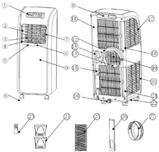
PARTS
-
Control panel
-
Horizontal louver
-
Vertical louver
-
Air outlet frame
-
Vertical Louvre connecting lever
-
Caster
-
Horizontal louver connecting lever
-
Main vertical louver
-
Front shell
-
Handle position
-
Back shell
-
C shape buckle of the heat exhaust
-
Power cord
-
Lower air duct bottom
-
Wire-winding post
-
Drain cap
-
Evaporator filter mesh
-
Evaporator filter frame
-
Radiating fine mesh
-
Condenser filter mesh
-
Condenser filter frame
-
Base plate (Right side: remote control storage area)
-
Remote control
-
Heat exhaust hose outer connector
-
Heat exhaust hose exhaust hose snap
-
Window sealing board assembly
-
Round Connector
\*\*\* TRISTAR Instruction manual
INSTALLATION
- Warning: leave this mobile air-conditioner in an upright position for at least 2 hours before first use.
- This air-conditioner may be moved indoor conveniently; leave the air-conditioner in an upright position while moving it. The air-conditioner shall be placed on a flat ground surface. Do not install or operate this air-conditioner in a bathroom or other wet environments.
ASSEMBLY
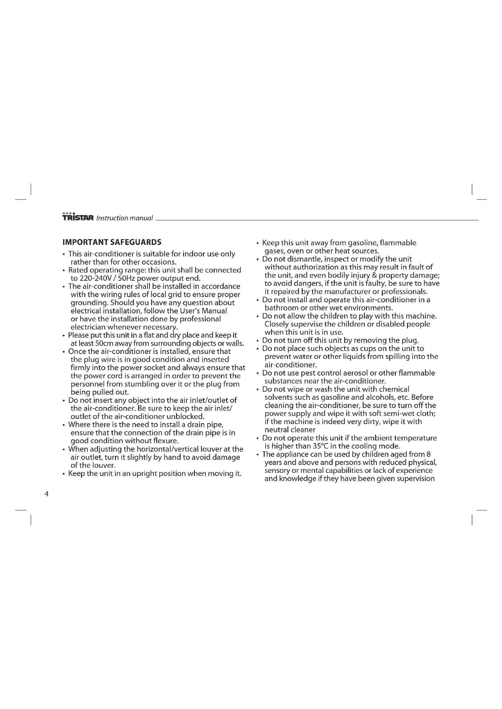
Heat exhausts hose
• Heat exhausts outer connector (Figure 1A)
• Heat exhaust hose short connector (Figure 2A)
- Heat exhausts outer connector (Figure 1)
• Take out the two pieces of the heat exhaust hose outer connector, these two pieces are the same in structure.
- Hold one piece with each hand, put the joint of one piece toward the other one's groove, and press them to make them snap tightly (Figure 1A).
• Take out the heat exhaust hose both connectors, screw both connectors into the heat exhaust hose (Figure 1 + 2A).
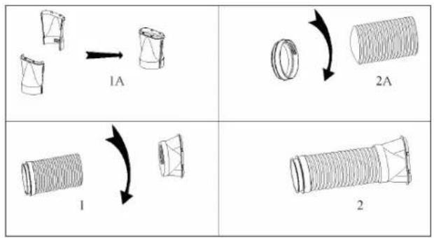
Installation of the C shape buckle of the heat exhaust hose
Place the rotatory hole of the C shape buckle over the rotation shaft on the back of the unit (as shown in Figure 3).
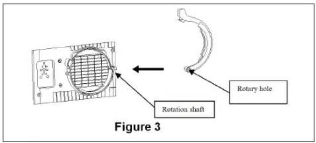
Installation of the heat exhaust hose
- Lift up the C shape buckle with one hand and place with your other hand the short connector of the heat exhaust hose in de recess on the back of the unit. (as shown in Figure 5).
- Lock exhaust hose firmly by pushing the C shape buckle downwards until it clicks. (as shown in Figure 5).
Installation of the window sealing board assembly
- Open the window and mount the window sealing board assembly onto the window, either vertically or horizontally (as shown in Figure 7 and 8).
- Pull apart the parts of the window sealing board assembly, adjust the distance of the assembly so the two ends of the assembly will come into contact with the window frame, fasten the parts of the assembly with copper screws.
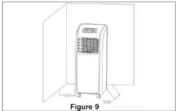
Installation of the unit
- Make sure the unit is placed with at least 50cm away between the walls or other objects. (As shown in Figure 9).
- Snap the flat end of the heat exhaust hose into the elliptical hole of the window sealing board assembly (as shown in Figure 10 and 11).
Important notes
- The exhaust hose is 280mm-1500mm long and this length is determined based on the specification of the air-conditioner (s). Do not use prolonged hose or replace with other different hoses as this may affect the functions of the air-conditioner. The exhaust must be smooth and the air-conditioner may overheat if the exhaust is obstructed.
- The heat exhaust hose may not be bent and shall be free from significant (greater than 45^ ) flexure, the heat exhaust hose shall be ventilated properly.
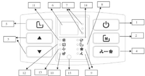
OPERATION INSTRUCTIONS OF THE CONTROL PANEL
- On/Off Button
- Mode Button
- Up/Down Button
- Fan Button
- Timer Button
- Double 88 display area
- Celsius/ Fahrenheit degree indicator
-
Timer indicator
-
High/Low indicator
10.Full water indicator
11.Cool indicator - Dehumidify indicator
13.Fan indicator
14.Sleep mode indicator
15.Remote control sensor location
flowchart
graph TD
    A["1"] --> B["2"]
    B --> C["3"]
    C --> D["4"]
    D --> E["5"]
    E --> F["6"]
    F --> G["7"]
    G --> H["8"]
    H --> I["9"]
    I --> J["10"]
    J --> K["11"]
    K --> L["12"]
    L --> M["13"]
    M --> N["14"]
    N --> O["15"]
    O --> P["16"]
    P --> Q["17"]
    Q --> R["18"]
    R --> S["19"]
    S --> T["20"]
    T --> U["21"]
    U --> V["22"]
    V --> W["23"]
    W --> X["24"]
    X --> Y["25"]
OPERATION INSTRUCTIONS:
- When the unit be plugged in for the first time, the buzzer will beep, the display will show the ambient temperature and the temperature display range is 10—35 °C. The unit enters the standby mode.
- Press the on off button to start or shut down the unit. The unit will enter in the cooling mode. The fan speed is high and the set temperature is 23°C.
- Press the mode button to switch among cooling, air supplying, and drying modes. In the meanwhile, corresponding indicators will illuminate.
- Cooling mode: Press Mode Button to choose this mode. In this mode,
press the Up/Down Button to set desired temperature. The temperature range is 17\~30°C. One press makes the temperature rise or fall 1°C. Press Fan Button to choose suitable fan speed. Press Timer Button + Down Button together and to choose Sleep mode. Under this mode, after the unit operates for 2 hours, the setting temperature raises 1°C automatically. After operating for another 2 hours, the setting temperature raises 1°C again. After that, the setting temperature won't change.
- In the dry mode, if the ambient temperature is higher than 17^ , the compressor will start. When the ambient temperature will come below 15^ , the compressor shuts down. When the ambient temperature rises to be higher than 17^ , the compressor starts again.
- In the air supply mode, only the fan motor works.
Fan button
The fan will operate in the following manners in the cooling mode (except the sleep mode) and air supply mode: high > low > high.
Timer button
- During operation press the Timer button to enter the shutdown time.
- During standby press the Timer button to enter the start time. In the meanwhile, the timer indicator will illuminate.
- Press the Timer button to enter the timing function (start/ shutdown). Use the up or down button to set the desired time in hours.
- After the start or shutdown time is set, the timer indicator will extinguish and the ambient temperature is displayed.
Up/ down button
- Press the up button or down button when displaying the ambient temperature, the ambient temperature will change to the desired temperature (the unit will not respond to this operation in the air supply and dry modes).
- In the cooling mode, the temperature setting range is 17\~30°C.
- Press the up and down button simultaneously to switch between the Fahrenheit degree and Celsius degree. When the Celsius degree is displayed, the Celsius degree indicator illuminates.
\*\*\* TRISTAR Instruction manual
WATER DRAINAGE
Manual(Figure 12)
- Once the unit shuts down upon full water, turn off the unit and unplug the power plug.
- Put a tray for the water below the water outlet at the back of the unit.
- Screw off the drain cap, unplug the water plug and water will flow out.
- Tilt the unit slightly backward when draining.
- If the water tray is full before the unit is empty block the water outlet with the water plug as soon as possible to prevent the water from flowing onto the ground or carpet.
- Once the water is fully drained, insert the water plug and screw on the water cap tightly.
- Turn on the unit only after the water plug and drain cap are installed properly; otherwise, the condensate of the unit will flow onto the ground or carpet.
Continuous drain (Figure 13 + 14)
- Screw off the water cap insert a 13mm PVC drain hose 8mm-10mm into the water outlet.
- Connect the drain hose to the toilet or outdoor.
- When operating in the heating mode, adopt continuous drain; otherwise, the unit may shut down due to full water.
- Put the drain hose in an inaccessible place at a height not above the water outlet and keep the drain hose free from flexure.
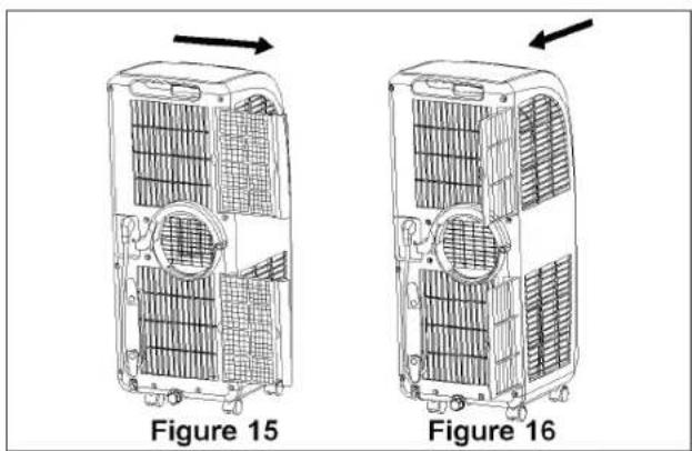
Maintenance and Servicing
Prior to maintenance and servicing of the unit, turn off the power and unplug the plug.
- Clean the surface of the unit with wet soft cloth. Do not use chemical solvents such as alcohol and gasoline; otherwise, the surface of the air-conditioner may be damaged.
- Clean the filters once every two weeks. If the filter frame and filter are clogged with dust, the function of the air-conditioner may decrease
- Take out the filter frame gently in the direction shown by the arrow (as shown in Figure 15 + 16).
- Put the filters into warm water (about 40^ ) to which neutral cleaner is added for cleaning and then dry them in the shade.
- Make sure the filters are completely dry before placing them back in the unit.
TROUBLESHOOTING
| Problem/fault indication | Cause Remedy | |
| The air-conditioner does not work | No powerFull water indicator illuminates?Ambient temperature too low?The room temperature is lower than the set temperature in the cooling mode. | Connect the unit to a live socket and turn it on.Drain the water stored in the unit.It is recommended that this unit be operated at 10-35°C.Change the set temperature |
| Bad cooling or heating effects | There is direct sunlightThe doors and windows are open, the room is crowded or there are other heat sources in the cooling modeFilter mesh very dirtyAir inlet or air outlet clogged | Draw the curtain on.Close the door and window and add new air-conditionersClean or replace the filter meshRemove the obstruction |
| Large noise • Air-conditioner not put on a flat surface | Put the air-conditioner in a flat and firm place (may reduce noise) | |
| The compressor does not work | Initiation of overheat protection. | Wait 3 minutes until the temperature decreases and then turn on the unit |
| The remote control does not work | Too long a distanceThe remote control does not point toward the receiving head of the remote controlThe batteries have no electricity | Bring the remote control close to the air-conditioner and ensure that the remote control points toward the receiving head of the remote control.Replace the batteries |
| Display E1 • Pipe temperature sensor failure | Check the pipe temperature sensor and related circuits | |
| Display E2 • Room temperature sensor failure | Check the room temperature sensor and related circuits | |
| Display E4 • Anti-freeze protection • Restore the functions | automatically once defrozen. | |
| Full water indicator illuminates | The water in the baseplate of the unit reaches the full water level | Drain the water in the baseplate. |
GUARANTEE
- This product is guaranteed for 24 months granted. Your warranty is valid if the product is used in accordance to the instructions and for the purpose for which it was created. In addition, the original purchase (invoice, sales slip or receipt) is to be submitted with the date of purchase, the name of the retailer and the item number of the product.
- For the detailed warranty conditions, please refer to our service website: www.service.tristar.eu

ENVIRONMENT
This appliance should not be put into the domestic garbage at the end of its durability, but must be offered at a central point for the recycling of electric and electronic domestic appliances. This symbol on the appliance, instruction manual and packaging puts your attention to this important issue. The materials used in this appliance can be recycled. By recycling of used domestic appliances you contribute an important push to the protection of our environment. Ask your local authorities for information regarding the point of recollection.
SUPPORT
You can find all available information and spare parts at service.tristar.eu!
ES
PT
PL
★★★
Przycisk wentylatora (FAN)
IT
★★★
TRISTAR
Bruksanvisning
INSTALLATION
★★★●
TRISTAR
Návod na použití
INSTALACE
DÔLEŽITÉ BEZPEČNOSTNÉ POKYNY
★★★●
TRISTAR
Návod na použitie
INŠTALÁCIA
The product or equipment contains fluorinated greenhouse gas.
Quality shouldn't be a luxury!

service.tristar.eu
Tristar Europe B.V. | Jules Verneweg 87 | 5015 BH Tilburg | The Netherlands