LS 3 - Exercise bike Christopeit - Free user manual and instructions
Find the device manual for free LS 3 Christopeit in PDF.

| Product type | Exercise bike |
| Brand | Christopeit |
| Model | LS 3 |
| Order number | 9717 |
| Braking system | Magnetic |
| Drive system | V-belt |
| Flywheel weight | Approx. 8 kg |
| Number of resistance levels | 8 (continuous adjustment via transmission cable) |
| Pulse measurement | Integrated into handlebars (hand pulse grips) |
| Computer | 5 windows (speed, distance, time, calories, pulse) |
| Displays | Speed (km/h), distance (km), time (min:sec), calories (kcal), pulse (bpm) |
| Adjustable limit values | Pulse (high/low), time, distance, calories |
| Power supply | 2 AA batteries (1.5 V) |
| Dimensions (L x W x H) | 75 x 55 x 135 cm |
| Adjustments | Seat height, handlebar tilt, front transport wheels |
| Safety | TÜV tested, safety instructions included |
| Maintenance | Clean with mild detergents; regularly check tightness of screws |
| Spare parts | Available, detailed parts list provided |
| Warranty | Not specified, refer to dealer |
Frequently Asked Questions - LS 3 Christopeit
User questions about LS 3 Christopeit
0 question about this device. Answer the ones you know or ask your own.
Ask a new question about this device
Download the instructions for your Exercise bike in PDF format for free! Find your manual LS 3 - Christopeit and take your electronic device back in hand. On this page are published all the documents necessary for the use of your device. LS 3 by Christopeit.
USER MANUAL LS 3 Christopeit
natural_image
Exterior view of a modern exercise bike (no signage or text visible)D
Assembly and exercise instructions for Order No. 9717
NL
Schritt 2:
Schritt 3:
Schritt 4:
Schritt 7:
Schritt 8:
Schritt 9:
Kontrolle
- Summary of Parts Page 3 - 4
- Important Recommendations and Safety Information Page 12
- Parts List Page 13 - 14
- Assembly Instructions With Exploded Diagrams Page 15 - 17
- Computer instructions Page 18
- Training Instructions Page 19
Dear customer,
We congratulate you on your purchase of this home training sports unit and hope that we will have a great deal of pleasure with it. Please take heed of the enclosed notes and instructions and follow them closely concerning assembly and use.
Please do not hesitate to contact us at any time if you should have any questions.
Important Recommendations and Safety Information
Our product has been tested by TÜV-GS and meets the latest and toughest safety standards. This fact does not however mean that you can fail to closely observe the following basic points:
-
Assemble the equipment according to the assembly instructions and only use the individual parts enclosed for assembly of the equipment and which are listed in the parts list as being specifically for this equipment. Before you start assembly, check against the delivery to make sure that everything has been delivered, and check against the packing list to make sure all the parts have been enclosed.
-
Check before the equipment is first used, and again at regular intervals, that all screws, bolts, nuts and other connections have been done up tightly, to ensure that your training equipment is in a safe operating condition at all times.
-
Place the equipment on a dry, level surface and protect it against damp and wetness. If you wish to protect the area underneath the equipment against damage from pressure or from becoming dirty or the like, we recommend that you place a suitable non-slip item under the equipment (such as a rubber mat or sheet of wood).
-
Always wear training clothing and shoes that are suitable for fitness training when you are doing training work on the equipment. The clothing must be of a type that will not hang down during training due to its shape (e.g., length). Shoes should be selected for their suitability when using the training equipment, primarily so that they provide a secure grip for the foot and have a non-slip sole.
-
Remove any objects from a vicinity of 2 meters avound the equipment before you start any training work.
-
In general, you should consult your doctor before starting targeted training work. He can make a definitive statement as to the maximum exertion (pulse rate, wattage, duration of training, etc.) you can set for yourself and can also give you detailed information with respect to the correct body position during training, your training target, and questions of diet.
It is to take care that this item is not useable for therapeutic purpose. Exercise never after heavy meals.
-
Only carry out training work on the equipment when it is in perfect working order. Only use original spare parts in the event of a repair.
-
If it has not been explicitly stated otherwise in the instructions, the equipment may only be used by one person for training.
-
If you experience giddiness, nausea, chest pains or other abnormal symptoms, stop the training at once and see a doctor.
- In general, sports training equipment is not a toy. It may only be used in an appropriate manner and by persons who have been suitably informed or instructed.
- Children, invalids and the handicapped should only use the equipment in the presence of another person who can provide assistance and instruction.
- Always pay attention that you or any other persons never bring parts of the body in close proximity to any parts of the equipment that are still moving.
- When making settings for any adjustable parts, check that they are in the right position and also check the marked maximum setting.
- Do not use strong solvents for cleaning, and only use the tools supplied, or suitable ones of your own, for any repairs that may be required.
- Please dispose of the packaging and any parts that have to be replaced subsequently (all parts for the unit) at suitable collecting points or containers with a view to saving the environment.
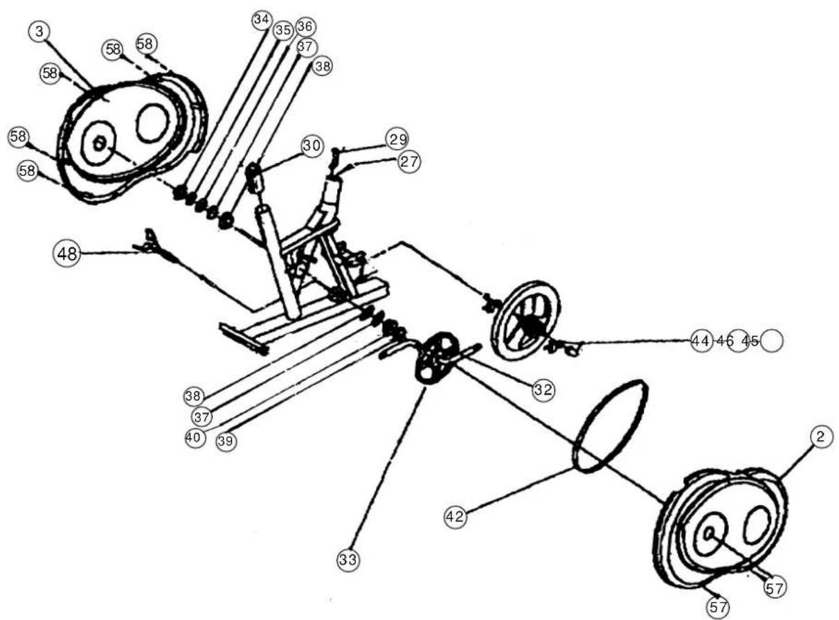
Parts List – Spare Parts List
LS 3 Order No. 9717
Technical data: Issue: 01. 05. 2001
Magnetic home trainer with hand pulse measurement -
5-window computer
Magnetic braking system, V-belt drive.
approx. 8 kg centrifugal mass, 8-speed gears
Hand pulse measurement integrated in the handlebars
Saddle height and handlebar inclination adjustable, front transport rollers
Easy to use 5-window computer with simultaneous
display of: speed, distance, time, approx. calory consumption and pulse rate.
Entry of limits such as upper/lower pulse limits, time, distance and approx. calory consumption.
Exceeded limits are displayed.
Space requirement approx. L 75, W 55, H 135 cm
Please check after opening the packing that all the parts shown in the following parts lists are there. Once you are sure that this is the case, you can start assembly.
Please contact us if any components are defective or missing, or if you need any spare parts or replacements in future:
Assembly Instructions
Before beginning assembly, be sure to observe our recommendations and safety instructions.
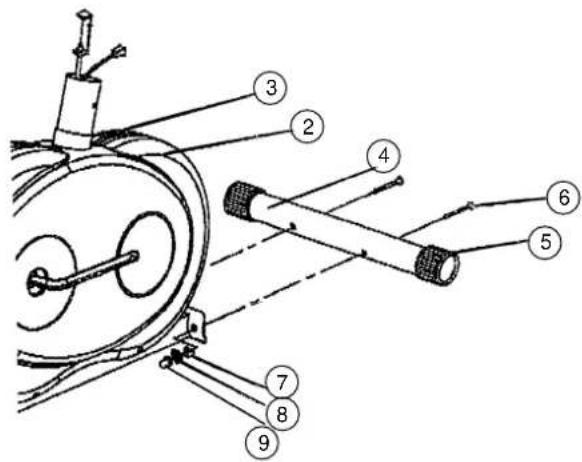
Step 1:
Installation of the front footbar (4) on the main frame (1) with carriage bolts M8x75 (6), washers 8//20 (7), spring washers for M8 (8) and cap nuts M8 (9).
- Place screws (6) and two each washers (7), spring washers (8) and nuts (9) accessibly beside the front part of the main frame (1).
- Insert the footbar (4) in the holder of the main frame (1) and adjust so that the hole patterns of the holder and the footbar (4) are aligned.
-
Push one screw (6) through each hole.
-
Fit the screw ends of (6) with one washer (7) and one spring washer (8) each and fasten with a nut (9).
Items 5 are pre-assembled.
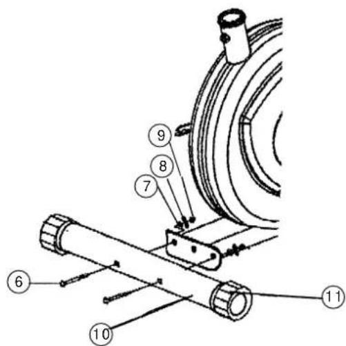
Step 2:
Installation of the front rear (10) on the main frame (1) with carriage bolts M8x75 (6), washers 8//20 (7), spring washers for M8 (8) and cap nuts M8 (9).
- Place screws (6) and two each washers (7), spring washers (8) and nuts (9) accessibly beside the rear part of the main frame (1).
- Insert the footbar (10) in the holder of the main frame (1) and adjust so that the hole patterns of the holder and the footbar (10) are aligned.
- Push one screw (6) through each hole.
- Fit the screw ends of (6) with one washer (7) and one spring washer (8) each and fasten with a nut (9). (Note: If the machine is placed for training on an uneven floor, this can be compensated at any tome by turning the eccentric caps (119:
Items 11 are pre-assembled.
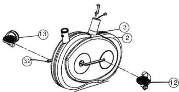
Step 3:
Installation of the right pedals (12) and the left pedals (13) on the pedal crank (32).
- The pedals are marked "R" for right and "L" for left.
- Screw the right pedals (12) into the treaded hole on the right hand side of the pedal crank (32) and tighten firmly. (Note: Right and left are specified as viewed seated on the machine during training. It must also be observed that the threaded part of the right pedal must be screwed clockwise into the threaded hole of the pedal crank.)
- Screw the left pedal (13) into the threaded hole on the left hand side of the pedal crank (32) and tighten firmly. (Note: The threaded part of the left pedal must be screwed anticlockwise into the threaded hole of the pedal crank.)
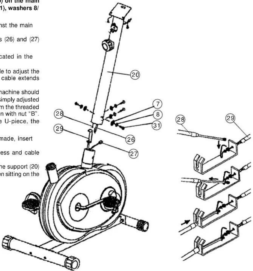
Step 4:
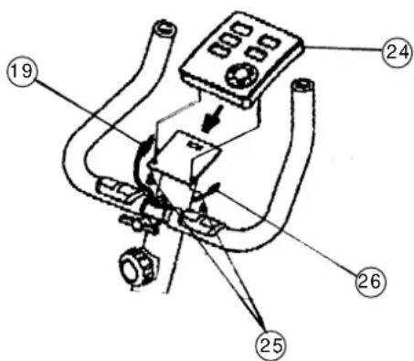
Connecting the computer cable harness incl. sensor (27) to the computer cable harness
(26), connection of the cable of the resistance adjuster (28) with the cable (29) and installation of the handlebar support (20) on the main frame (1) with the round-headed Allen screws M8x20 (31), washers 8/20 (7) and spring washers for M8 (8).
- Place the lower end of the handlebar support (20) against the main frame (1). Plug the ends of the two computer cable harnesses (26) and (27) projecting from (1) and (20) together.
- Join the two ends of the cables (28) and (29) as indicated in the drawing below. (Note: Before this step of the installation, it is advisable to adjust the resistance setting to the highest stage, at which the cable extends furthest from the sheath. If the factory adjusted pedal resistance range of the machine should later be found to be too great or too small, this can be simply adjusted as the cables. For this, loosen nut "B" of cable (29), turn the threaded piece "A" correspondingly and secure the new position with nut "B". In this respect: The further "A" is screwed into the U-piece, the greater the resistance, and the converse.)
- When the harness and cable connections have been made, insert the handlebar support (20) into the main frame (1). (Note: When joining the tubes, ensure that the harness and cable connections are not trapped. The resistance adjuster installed at the upper end of the support (20) must point backwards (opposite to the line of sight when sitting on the machine during training.)
- Put one spring washer (8) and one washer (7) on each screw (31). Push the screws (31) through the holes in the support (29), screw into the threaded holes of the main frame (1) and tighten firmly.
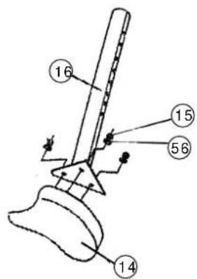
Step 5:
Installation of the saddle (14) on the saddle support (16) with the washers 8//20 mm (56) and the self-locking nuts M8 (15).
- Place the saddle with the seat surface downwards.
- Place the retaining plate of the saddle support (16) on the upwards pointing bottom of the saddle. The threaded pieces on the bottom of the saddle must project through the corresponding holes in the retaining plate of the saddle support.
- Place washers (56) on the threaded pieces, screw on nuts (15) and tighten firmly.
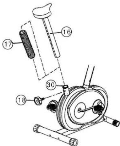
Step 6:
Installation of the saddle support (16) incl. the saddle support wrapping (17) on the main frame (1) with the handgrip screw (18).
- Push the saddle support wrapping (17) onto the saddle support (16).
- Insert the saddle support (16) into the provided holder of the main frame (1) and secure at the desired position by screwing in the handgrip screw (18). (Note: To screw in the handgrip screw (18), the threaded hole in the main frame (1) and one of the holes in the saddle support (16) must be aligned. Furthermore, ensure that the saddle support (16) is not pulled out of the main frame beyond the marked maximum adjustment position. The setting of the saddle support can be adjusted as desired later.)
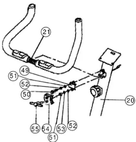
Step 7:
Installation of the handlebars (21) on the handlebar support (20) with the clip (49), the round-headed Allen screw (50), the washers (51), the spring washers (52), the spacer (53), the clip cover (54) and the wing bolt (55).
- Place the above named parts and the handlebars accessibly beside the machine. Put one spring washer (52) and one washer (51) on screw (50). Push screw (50) through one of the two holes in the clip (49). Hold this unit with one hand.
- With the other hand, take the handlebars and place the knurled centre of the handlebars centrally in the holder of the handlebar support (20). Screw the bolt of the unit assembled in Step 1 into the upper threaded hole of the holder of the handlebar support (20) and tighten until the handlebar is held by the clip (49).
- Push the spacer (53), the spring washer (52) and the washer (51) onto the wing bolt (55). Push the clip cover (54) onto the clip (49). Push the wing bolt (55) through the hole in the clip cover (54) and the clip (49) and screw lightly into the lower threaded hole behind these in the holder of the handlebar support (20).
- Set the handlebars (21) to the desired position and tighten the wing bolt (55) firmly. Then tighten screw (50) firmly. (Note: The setting of the handlebars (21) can be adjusted as desired later. For this, the screw (50) and the wing bolt (55) must be sufficiently loosened, the handlebars adjusted and the screw (50) and the wing bolt (55) retightened firmly.)
Items 19, 21, 22 and 23 are preassembled.
Step 8:
Installation of the computer (24) on the computer bracket of the handlebar support (20) with the fillister-head Philips screw M5x10mm (25).
- Push the computer onto the bracket at the upper end of the handlebar support.
- Push one each of the screws (25) from beneath through the corresponding holes of the computer bracket, screw into the threaded holes in the bottom of the computer and tighten.
- The computer cable harness of the handlebar support (26) projects from the top of the handlebar support (20). Plug the plug at the end of this harness into the socket of the harness at the rear of the computer (SENSOR INPUT).
- The cable harness of the pulse measuring handle unit (19) projects from the handlebars (21). Plug the plug at the end of this harness into the socket of the harness at the rear of the computer (PULSE INPUT). (Note: When connecting the computer, ensure that the cable harnesses (19) and (26) are not trapped. Insert the necessary batteries (2xMignon 1.5V AA) in the battery compartment located on the rear of the computer.)
Step 9:
Checks
-
Check the correct installation and function of all screwed and plug connections.
Installation is thereby complete. -
When everything is in order, familiarise yourself with the machine at a low resistance setting and make your individual adjustments.
Note:
Please keep the tool set and the instructions in a safe place as these may be required for repairs or spare parts orders becoming necessary later.
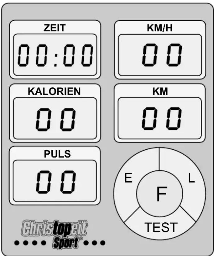
The supplied computer allows the most convenient training. Every value relevant to training is displayed in a corresponding window.
From the beginning of the training session, the required time, the current speed, the approximate caloric consumption, the travelled distance ad the current pulse rate are displayed. All values are counted from zero upwards.
The computer is switched on by briefly pressing the F key or simply by beginning training. The computer begins to register and display all values. To stop the computer, just stop training. The computer stops all measurements and retains the last attained values. The last attained values in the functions TIME, CALORIES and KM are stored and training can continue with these values when training is resumed.
The computer switches of automatically approx. 4 minutes after training is stopped. All values attained until that time are stored and are displayed again when training is resumed. It is then possible to continue training from these values or to reset all functions to zero using the L key.
Displays:
1. "PULSE" display:
The current pulse rate is displayed in beats per minute. It is possible to specify a particular value using the "E" key.
When an upwards pointing arrow appears at the side of the window, it is possible to enter a value for the upper pulse rate limit. When the "F" key is pressed again, a downwards pointing arrow appears, indicating that a value for the lower pulse rate limit can be entered.
If a particular upper and/or lower pulse rate limit has been specified, an acoustic signal will indicate if these limits are infringed.
The values last attained by this function are not stored.
(Limit of both displays: 40 - 240 pulse beats per minute.)
Note:
For pulse measurement, the two contact surfaces of the pulse measuring handle unit (19) must be gripped simultaneously. The contact surfaces should be located centrally in the palms of the hands.
2. "TIME" display:
The currently required time is displayed in minutes and seconds. It is possible to specify a particular value using the "E" key. If a particular time has been specified, the remaining time is displayed. When the specified value is attained, this is indicated by an acoustic signal.
The values last attained by this function are stored.
(Limit of the display: 99.59 minutes.)
3. "KM/H" display:
The current speed is displayed in kilometres per hour. It is not possible to specify a particular value using the "E" key. The values last attained by this function are not stored.
(Limit of the display: 99.9 km/h.)
4. "CALORY" display:
The current status of the consumed calories is displayed. It is possible to specify a particular value using the "E" key. If a particular consumption has been specified, the remaining number of calories to be consumed is displayed. When the specified value is attained, this is indicated by an acoustic signal.
The values last attained by this function are stored.
(Limit of the display: 999 calories.)
5. "KM" display:
The current status of the travelled distance is displayed. It is possible to specify a particular value using the “E” key. If a particular distance has been specified, the remaining distance is displayed. When the specified value is attained, this is indicated by an acoustic signal.
The values last attained by this function are stored.
(Limit of the display: 999 km.)
Keys:
1. "E" key:
By pressing this key once, it is possible to specify values step by step in the respective functions. For this, the desired function must firstly be selected using the "F" key.
Holding the key pressed activates faster running, which can be stopped by pressing the key again. When training begins, the specified values are then counted down to zero.
2. "F" key:
Pressing this key once briefly makes it possible to change from one function to another, i.e. the respective functions can be selected for which entries can be made using the "E" key. The currently selected function is indicated by an icon in the respective window.
3. "L" = Delete:
When this key is pressed briefly, the values chosen with the "F" key are reset to zero.
Holding the key pressed (approx. 5 seconds) allows all last attained values to be deleted. All values of all displays are then set to zero.
"TEST" key:
With this key, a test can be conducted to assess your fitness. The grades F1 (highest mark = high fitness) to F6 (lowest mark = low fitness) are awarded.
To be able to conduct this test, the training session must have been completed, the "TEST" key pressed and the contact surfaces of the pulse measuring handle unit (19) must be gripped. All functions disappear and only the time display indicates a one minute countdown. During this time, the contact surfaces of the pulse measuring handle unit (19) must be gripped with both hands. The corresponding grade is then displayed in the PULSE display. To return to the main menu, press the Test key again.
Training instructions
You must consider the following factors in determining the amount of training effort required in order to attain tangible physical and health benefits:
1. Intensity:
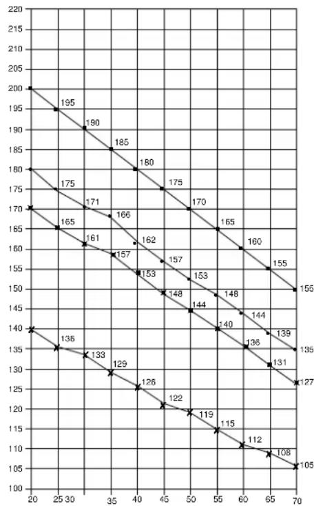
The level of physical exertion in training must exceed the level of normal exertion without reaching the point of breathlessness and / or exhaustion. A suitable guideline for effective training can be taken from the pulse rate. During training this should rise to the region of between 70% to 85% of the maximum pulse rate (see the table and formular for determination and calculation of this).
During the first weeks, the pulse rate should remain at the lower end of this region, at around 70% of the maximum pulse rate. In the course of the following weeks and months, the pulse rate should be slowly raised to the upper limit of 85% of the maximum pulse rate. The better the physical condition of the person doing the exercise, the more the level of training should be encreased to remain in the region of between 70% to 85% of the maximum pulse rate. This should be done by lengthening the time for the training and / or encreasing the level of difficulty.
If the pulse rate is not shown on the computer display or if for safety reasons you wish to check your pulse rate, which could have been displayed wrongly due to error in use, etc., you can do the following:
a. Pulse rate measurement in the conventional way (feeling the pulse at the wrist, for example, and counting the number of beats in one minute).
b. Pulse rate measurement with a suitable specialised device (available from dealers specialising in health-related equipment).
2.Frequency
Most experts recommend a combination of health-conscious nutrition, which must be determined on the basis of your training goal, and physical training three times a week. A normal adult must train twice a week to maintain his current level of condition. At least three training sessions a week are required to improve one's condition and reduce one's weight. Of course the ideal frequency of training is five sessions a week.
3. Planning the training
Each training session should consist of three phases: the warm-up phase, the training phase, and the cool-down phase. The body temperature and oxygen intake should be raised slowly in the warm-up phase. This can be done with gymnastic exercises lasting five to ten minutes.
Then the actual training (training phase) should begin. The training exertion should be relatively low for the first few minutes and then raised over a period of 15 to 30 minutes such that the pulse rate reaches the region of between 70% to 85% of the maximum pulse rate.
In order to support the circulation after the training phase and to prevent aching or strained muscles later, it is necessary to follow the training phase with a cool-down phase. This should be consist of stretching exercises and / or light gymnastic exercises for a period of five to ten minutes.
4. Motivation
The key to a successful program is regular training. You should set a fixed time and place for each day of training and prepare yourself mentally for the training. Only train when you are in the mood for it and always have your goal in view. With continuous training you will be able to see how you are progressing day by day and are approaching your personal training goal bit by bit.
line
| X | Y | |---|---| | 20 | 200 | | 25 | 195 | | 30 | 190 | | 35 | 185 | | 40 | 180 | | 45 | 175 | | 50 | 170 | | 55 | 165 | | 60 | 160 | | 65 | 155 | | 70 | 150 | | 20 | 170 | | 25 | 165 | | 30 | 161 | | 35 | 157 | | 40 | 153 | | 45 | 148 | | 50 | 144 | | 55 | 140 | | 60 | 136 | | 65 | 131 | | 70 | 127 | | 20 | 140 | | 25 | 135 | | 30 | 133 | | 35 | 129 | | 40 | 126 | | 45 | 122 | | 50 | 119 | | 55 | 115 | | 60 | 112 | | 65 | 108 | | 70 | 105 | The chart displays a single descending trend line connecting two series of data points labeled '1'. The x-axis ranges from 20 to 70 and the y-axis ranges from 100 to 220.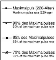
Calculation formula: Maximum pulse rate = 220 - age
(220 minus your age)
90% of the maximum pulse rate = (220 - age) x 0.9
85% of the maximum pulse rate = (220 - age) x 0.85
70% of the maximum pulse rate = (220 - age) x 0.7
F
Sommaire
Dimensions approximatives :
Dimensions approximatives :
Etape n° 2:
Etape n° 3:
Etape n° 4:
Etape n° 7:
Etape n° 8:
Etape n° 9:
Contrôle
STAP 2:
STAP 3:
STAP 4:
STAP 7:
STAP 9:
Controle:
3. Planning van de training
Passo 2:
Passo 3:
Passo 4:
Passo 9:
Controllo
line
| X-axis | Maximalpuls (220-Altor) Maximum pulse rate (220 ags) | 90% des Maximalpulses 90% of the maximum pulse rate | 85% des Maximalpulses 85% of the maximum pulse rate | 70% des Maximalpulses 70% of the maximum pulse rate | |---|---|---|---|---| | 20 | 195 | 175 | 180 | 170 | | 25 | 190 | 171 | 185 | 165 | | 30 | 185 | 166 | 180 | 161 | | 35 | 180 | 162 | 175 | 157 | | 40 | 175 | 157 | 170 | 153 | | 45 | 170 | 153 | 165 | 148 | | 50 | 165 | 148 | 160 | 144 | | 55 | 160 | 144 | 155 | 140 | | 60 | 155 | 140 | 150 | 136 | | 65 | 150 | 136 | 145 | 131 | | 70 | 145 | 133 | 140 | 127 | The chart displays a single data series representing the maximum pulse rate for each threshold level. The values are explicitly labeled on the chart at the top of each data point. The x-axis ranges from 20 to 70, and the y-axis ranges from 100 to 220. The legend indicates four distinct threshold categories: Maximalpuls (220-Altor), 90% des Maximalpulses (90% of the maximum pulse rate), 85% des Maximalpulses (85% of the maximum pulse rate), and 70% des Maximalpulses (70% of the maximum pulse rate). The data points are connected by lines forming a descending diagonal from top-left to bottom-right. The chart is saved as a PNG file named 'maximalpuls'.War 2:
War 3: