EM 3 - Exercise bike Christopeit - Free user manual and instructions
Find the device manual for free EM 3 Christopeit in PDF.

User questions about EM 3 Christopeit
0 question about this device. Answer the ones you know or ask your own.
Ask a new question about this device
Download the instructions for your Exercise bike in PDF format for free! Find your manual EM 3 - Christopeit and take your electronic device back in hand. On this page are published all the documents necessary for the use of your device. EM 3 by Christopeit.
USER MANUAL EM 3 Christopeit
natural_image
Person exercising on an exercise bike, no visible text or symbols
text_image
EM3 980 (weEM3 Spirit
98081 C
(weiß/türkis)
D
Assembly and exercise instructions
for Order No. 9808C/98081C
NL
text_image
Exploded view diagram of a stationary exercise machine with numbered components and labeled partstext_image
Technical diagram of a mechanical device with numbered components and alignment indicatorsSchritt 2:
text_image
Technical diagram of a stationary exercise machine with numbered components for identificationSchritt 3:
text_image
Diagram of a mechanical device with numbered parts, likely illustrating a linkage or assembly process.text_image
Technical diagram of a robotic arm with numbered components and directional arrows indicating movement or assembly.text_image
Technical diagram of a mechanical device with numbered parts and directional arrows indicating motion or assembly.Schritt 6: Montage der Pedalen (68L+68R) an den Pedalarmen (69L+69R).
text_image
Technical line drawing of an exercise bike with numbered components and labeled partsnatural_image
Line drawing of a mechanical device with a lever and adjustment arrow (no text or symbols)Wichtig:
text_image
STOP LEVEL
text_image
STOP LEVEL 1 515-
text_image
STOP LEVEL EELtext_image
STOP LEVEL
text_image
STOP LEVEL
text_image
STOP LEVELBenutzerprogramm U4
text_image
STOP LEVEL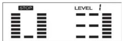
text_image
STOP LEVEL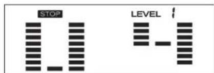
text_image
STOP LEVELProgramm 1: Manuell
natural_image
Simple line drawing of a person in a kneeling position with an arrow indicating motion (no text or symbols)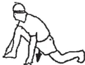
natural_image
Line drawing of a person in a kneeling position with a headband and motion arrow (no text or symbols)- Summary of Parts Page 3
- Important Recommendations and Safety Information Page 14
- Parts List (List of spare parts) Page 15 - 16
- Assembly Instructions With Exploded Diagrams Page 17 - 19
- Computer instructions Page 20 - 22
- Cleaning, Checks and Storage mount, Use & Dismount Page 23
- Training Instructions, Warm up
Page 24
Dear customer,
We congratulate you on your purchase of this home training sports unit and hope that we will have a great deal of pleasure with it. Please take heed of the enclosed notes and instructions and follow them closely concerning assembly and use.
Please do not hesitate to contact us at any time if you should have any questions.
Important Recommendations and Safety Instructions
Our products are all TÜV-GS tested and therefore represent the highest current safety standards. However, this fact does not make it unnecessary to observe the following principles strictly.
- Assembly the machine exactly as described in the installation instructions and use only the enclosed, specific parts of the machine contained in the assembly steps. Before assembling, verify the completeness of the delivery against the delivery notice and the completeness of the carton against the assembly steps in the installation and operating instructions.
- Check the firm seating off all screws, nuts and other connections before using the machine for the first time and at regular intervals to ensure that the trainer is in a safe condition.
-
Set up the machine in a dry, level place and protect it from moisture and water. Uneven parts of the floor must be compensated by suitable measures and by the provided adjustable parts of the machine if such are installed. Ensure that no contact occurs with moisture or water.
-
Place a suitable base (e.g. rubber mat, wooden board etc.) beneath the machine if the area of the machine must be specially protected against indentations, dirt etc.
-
Before beginning training, remove all objects within a radius of 2 metres from the machine.
-
Do not use aggressive cleaning agents to clean the machine and employ only the supplied tools or suitable tools of your own to assemble the machine and for any necessary repairs. Remove drops of sweat from the machine immediately after finishing training.
-
WARNING! Systems of the heart frequency supervision can be inexact. Excessive training can lead to serious health damage or to the death. Consult a doctor before beginning a planned training programme. He can define the maximum exertion (pulse, Watts, duration of training etc.) to which you may expose yourself and can give you precise information on the correct posture during training, the targets of your training and your diet. Never train after eating large meals.
-
Only train on the machine when it is in correct working order. Use original spare parts only for any necessary repairs. WARNING! Replace the worm parts immediately and keep this equipment out of use until repaired.
-
When setting the adjustable parts, observe the correct position and the marked, maximum setting positions and ensure that the newly adjusted position is correctly secured.
-
Unless otherwise described in the instructions, the machine must only be used for training by one person at a time. The exercise time should not overtake 60 min./daily.
-
Wear training clothes and shoes which are suitable for fitness training with the machine. Your clothes must be such that they cannot catch during training due to their shape (e.g. length). Your training shoes should be appropriate for the trainer, must support your feet firmly and must have non-slip soles.
- WARNING! If you notice a feeling of dizziness, sickness, chest pain or other abnormal symptoms, stop training and consult a doctor.
- Never forget that sports machines are not toys. They must therefore only be used according to their purpose and by suitably informed and instructed persons.
- People such as children, invalids and handicapped persons should only use the machine in the presence of another person who can give aid and advice. Take suitable measures to ensure that children never use the machine without supervision.
- Ensure that the person conducting training and other people never move or hold any parts of their body into the vicinity of moving parts.
- At the end of its life span this product is not allowed to dispose over the normal household waste, but it must be given to an assembly point for the recycling of electric and electronic components. You may find the symbol on the product, on the instructions or on the packing.
The materials are reusable in accordance with their marking. With the re-use, the material utilization or the protection of our environment. Please ask the local administration for the responsible disposal place. - To protect the environment, do not dispose of the packaging materials, used batteries or parts of the machine as household waste. Put these in the appropriate collection bins or bring them to a suitable collection point.
- For speed dependent operation mode, the braking resistance level can be adjustable manually and the variations of power will depend on the pedaling speed. For speed independent operation mode, the user can set the wanted power consumption level in Watt, constant power level will be kept by various braking resistance levels, that will be determined automatically by system. That is independent on the pedaling speed.
- The unit has a resistance device with 24 levels. This makes it possible to increase or reduce the braking resistance and thus the amount of effort required in the training. Pressing the (-) - button reduces the braking resistance and thus the amount of effort required in the training. Pressing the (+) -button increases the braking resistance and thus the amount of effort required in the training.
- The maximum permissible load (=body weight) is specified as 150 kg. This machine has been tested and certified in compliance with EN ISO 20957-1 and EN 957-5 „H,A“. This item’s computer corresponds to the basic demands of the EMV Directive of 2004/108/EC.
Parts list – List of spare parts EM 3 order No. 9808 C, 98081 C
Technical data: Issue: 01. 11. 2014
Ergometer according to Class EN 957-1/5 H/A with high precision indicator.
• Motor-controlled magnetic brake system
• Approx. 8 kg centrifugal mass
• 1 manually program
• 12 stored training programs
- 5 stored heart frequency training programs
• 4 individual programmes
• 1 body fat program
• 24 manually adjustable load steps
- 1 speed independent program (power control in steps of 5 Watt (40-250 Watt))
- AC- adapter
• Hand pulse measurement
• horizontally and vertically adjustable saddle (quick release)
- Saddle and handlebar inclination adjustable
- Saddle universal exchangeable
• Transport rollers at front foot
- Drink bottle with bottle rack
• Floor level compensation
- Training computer with digital display of: speed, distance, time, approx. calorie consumption, pulse frequency, pulse rate, Watts, Body fat analyse, Recovery and program profiles.
- Load max. 150 kg (Body weight)
• Suitable for a height of 160-205cm
Space requirement approx. L 110 x B 52 x H 148 cm Items weight: 30kg
Exercise space approx: min. 2,5m²
Please contact us if any components are defective or missing, or if you need any spare parts or replacements in future.
This product is created only for private Home sports activity and not allowed to us in a commercial or professional area. Home Sport use class H/A

text_image
0 5 10 15 20 25 30 35 40 45 50 55 60 65 70 75 80 85 90 95 100 mm| Illustration Designation Dimensions Quantity Attached to ET number | ET number | |||||
| No. | mm | illustration No. | 9808 | 98081 | ||
| 1 | Computer | 1 | 7 | 36-9808-33-BT | 36-9808133-BT | |
| 2 | Hand pulse sensor | 2 | 4 | 36-9613204-BT | 36-9613204-BT | |
| 3 | Handlebar end cap | 2 | 4 | 39-9847 | 39-9847 | |
| 4 | Handlebar | 1 | 7 | 33-9808-17-SI | 33-9808117-WS | |
| 5 | Hand pulse cable | 1 | 1+2 | 36-9613205-BT | 36-9613205-BT | |
| 6 | Connection cable | 1 | 1+26 | 36-9808-34-BT | 36-9808-34-BT | |
| 7 | Handlebar post | 1 | 27 | 33-9808-15-SI | 33-9808115-WS | |
| 8 | Handlebar Adjusting knob | 1 | 7 | 36-9211-16-BT | 36-9211-16-BT | |
| 9 | Bushing | 1 | 8 | 36-9613209-BT | 36-9613209-BT | |
| 10 | Handlebar shield cover | 1 | 7 | 36-9211-09-BT | 36-9211-09-BT | |
| 11 | Foam grip | 2 | 4 | 36-9808-35-BT | 36-9808-35-BT | |
| 12 | Bottle holder | 1 | 7 | 36-9913123-BT | 36-9913123-BT | |
| 13 | Bottle | 1 | 12 | 36-9808-50-BT | 36-9808-50-BT | |
| 14 | Self-tapping screw | 2 | 12 | 36-9210-30-BT | 36-9210-30-BT | |
| 15 | Washer | ∅20x∅8.2x1.2T | 4 | 16 | 39-9864-VC | 39-9864-VC |
| 16 | Button screw | M8x20 | 4 | 7 | 39-9886-CR | 39-9886-CR |
| 17 | Saddle | 1 | 19 | 36-9211-20-BT | 36-9211-20-BT | |
| 18 | Square cap | 2 | 19 | 39-9954 | 39-9954 | |
| 19 | Saddle slide | 1 | 21 | 33-9808-18-SI | 33-9808118-WS | |
| 20 | Saddle movable set | 1 | 19 | 36-9913107-BT | 36-9913107-BT | |
| 21 | Seat post | 1 | 27 | 33-9808-19-SI | 33-9808119-WS | |
| 22 | Washer | ∅ 20x ∅ 10.2x1.5T | 1 | 23 | 39-10207 | 39-10207 |
| 23 | Adjust knob | M 10 | 1 | 20 | 36-9814-14-BT | 36-9814-14-BT |
| 24 | Seat post bushing | 1 | 27 | 36-9808-06-BT | 36-9808-06-BT | |
| 25 | Rubber cover | 1 | 63 | 36-9808-07-BT | 36-9808-07-BT | |
| 26 | Motor cable | 1 | 6+41 | 36-9212-04-BT | 36-9212-04-BT | |
| 27 | Main frame | 1 | 33-9808-16-SI | 33-9808116-WS | ||
| 28 | Bolt | M5x10 | 4 | 1 | 39-9903 | 39-9903 |
| 29 | Sensor | 1 | 27 | 36-9212-07-BT | 36-9212-07-BT | |
| 30 | Spring washer | for M 6 | 6 | 38+53 | 39-9865-SW | 39-9865-SW |
| 31 | Bearing | 6003 | 2 | 27+37 | 39-9999 | 39-9999 |
| 32 | C-Clip | C 17 | 2 | 37 | 36-9504-20-BT | 36-9504-20-BT |
| 33 | Pulley | 1 | 37 | 36-9808-35-BT | 36-9808106-BT | |
| 34 | Belt tension | 2 | 49 | 39-10172 | 39-10172 | |
| 35 | Nylon nut | M 6 | 4 | 38 | 39-9816-VC | 39-9816-VC |
| 36 | Magnet | 1 | 33 | 36-9613222-BT | 36-9613222-BT | |
| 37 | Crank axle | 1 | 31 | 33-9808-08-SI | 33-9808-08-SI | |
| Illustration Designation Dimensions Quantity Attached to ET number ET number | ||||||
| No. mm illustration No. 9808 98081 | ||||||
| 38 | Bolt | M6x15 | 4 | 37 | 39-9911 | 39-9911 |
| 39 | Belt | 1 | 33+52 | 36-9808-12-BT | 36-9808-12-BT | |
| 40 | Washer | 12/24 | 2 | 55 | 39-10062 | 39-10062 |
| 41 | Adjustment Motor | 1 | 27 | 36-9212-08-BT | 36-9212-08-BT | |
| 42 | Screw | M5x60 | 1 | 27 | 39-10406 | 39-10406 |
| 43 | Tension wire | 1 | 41 | 36-9808-36-BT | 36-9808-36-BT | |
| 44 | Saddle adjustment knob | M14 | 1 | 27 | 36-9211-18-BT | 36-9211-18-BT |
| 45 | Wave washer | 17//22 | 1 | 37 | 36-9918-22-BT | 36-9918-22-BT |
| 47 | Nut | M10 | 3 | 49 | 39-9930-SW | 39-9930-SW |
| 48 | Flange Nut | M10 | 2 | 49 | 39-10256 | 39-10256 |
| 49 | Flywheel Axle | 1 | 50 | 33-9211-13-SI | 33-9211-13-SI | |
| 50 | Flywheel bearing | 2 | 51 | 39-9998 | 39-9998 | |
| 51 | Flywheel | 1 | 50 | 33-9808-20-SI | 33-9808-20-SI | |
| 52 | Small pulley | 1 | 49 | 33-9220-10-SI | 33-9220-10-SI | |
| 53 | Bolt | M6x15 | 2 | 55 | 39-10120-SW | 39-10120-SW |
| 54 | Washer | 6/12 | 2 | 55 | 39-10013-VC | 39-10013-VC |
| 55 | Magnetic clip | 1 | 54 | 33-9211-10-SI | 33-9211-10-SI | |
| 56 | Spring | 1 | 55 | 36-9808-37-BT | 36-9808-37-BT | |
| 57 | Nylon Nut | M8 | 2 | 60+61 | 39-9918-CR | 39-9918-CR |
| 58 | Flat washer | 5 | 60+72 | 39-10018-CR | 39-10018-CR | |
| 59 | Idler wheel bearing | 1 | 61 | 36-9808-17-BT | 36-9808-17-BT | |
| 60 | Bolt | M8x25 | 1 | 27+61 | 39-10455 | 39-10455 |
| 61 | Idler arm | 1 | 62 | 36-9808-38-BT | 36-9808-38-BT | |
| 62 | Magnets spring | 1 | 27+61 | 36-9808-39-BT | 36-9808-39-BT | |
| 63L | Chain cover left | 1 | 27+63R | 36-9808-51-BT | 36-9808131-BT | |
| 63R | Chain cover right | 1 | 27+63L | 36-9808-52-BT | 36-9808132-BT | |
| 64 | Top cover | 1 | 63L+63R | 36-9808-40-BT | 36-9808130-BT | |
| 65 | Self-tapping screw | M4x10 | 4 | 64 | 39-10185 | 39-10185 |
| 66 | Flange screw | M8x20 | 2 | 37 | 39-9886-CR | 39-9886-CR |
| 67 | Crank cap | 2 | 69 | 36-9840-15-BT | 36-9840-15-BT | |
| 68L | Pedal left | 1 | 69L | 36-9110-04-BT | 36-9110-04-BT | |
| 68R | Pedal right | 1 | 69R | 36-9110-05-BT | 36-9110-05-BT | |
| 69L | Crank arm left | 1 | 37 | 33-9808-21-SW | 33-9808-21-SW | |
| 69R | Crank arm right | 1 | 37 | 33-9808-22-SW | 33-9808-22-SW | |
| 70 | self-tapping screw | M5x20 | 18 | 4,5,41+63 | 39-10190 | 39-10190 |
| 71 | Front stabilizer | 1 | 27 | 33-9808-23-SI | 33-9808120-WS | |
| 72 | Carriage bolt | M8x60 | 4 | 71+76 | 39-10094-CR | 39-10094-CR |
| 73L | Front stabilizer Cap left | 1 | 71 | 36-9808-41-BT | 36-9808-41-BT | |
| 73R | Front stabilizer Cap right | 1 | 71 | 36-9808-42-BT | 36-9808-42-BT | |
| 74 | Cap nut | M8 | 4 | 72 | 39-9900-VC | 39-9900-VC |
| 75 | Rear stabilizer Cap | 2 | 76 | 36-9808-43-BT | 36-9808-43-BT | |
| 76 | Rear stabilizer | 1 | 27 | 33-9808-24-SI | 33-9808121-WS | |
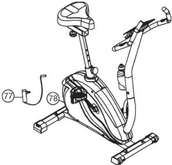
| 77 | Adapter | 6V=DC//1000mA | 1 | 78 | 36-9808-21-BT | 36-9808-21-BT |
| 78 | Connect wire for AC adapter | 1 | 77 | 36-9212-09-BT | 36-9212-09-BT | |
| 79 | Spring washer | for M8 | 8 | 16+72 | 39-9864-VC | 39-9864-VC |
| 80 | Nut | M5 | 2 | 42 | 39-10012 | 39-10012 |
| 81 | Flat washer | 1 | 8 | 39-10520 | 39-10520 | |
| 82 | Crank cap | 2 | 63L+63R | 36-9808-45-BT | 36-9808-45-BT | |
| 83 | Tool set | 1 | 36-9808-26-BT | 36-9808-26-BT | ||
| 84 | Assembly & exercise instructions | 1 | 36-9808-46-BT | 36-9808-46-BT | ||
Assembly Instructions
Remove all the separate parts from the packaging, lay them on the floor and check that all are there on the basis of the step drawings in these instructions for assembly and use. Please note that a number of parts have been connected directly to the main frame and preassembled. In addition, there are several other individual parts that have been attached to separate units. This will make it easier and quicker for you to assemble the equipment. Assembly time: 30 - 40 min.
Step 1:
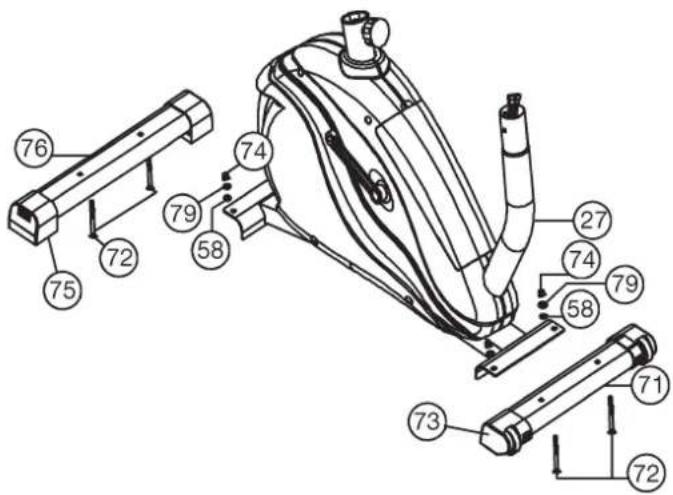
Attach the stabilizer (71+76) at main frame (27).
- Attach the front foot (71) with the preassembled transport rollers (73) to the main frame. Do this with the two screws (72), washers (58), spring washers (79) and cap nuts (74).
- Attach the rear foot (76) to the main frame (27). Do this with the two screws (72), washers (58), spring washers (79) and cap nuts (74). After assembly has been completed, you can compensate for minor irregularities in the floor by turning the adjusting screw of end cap (75). The equipment should be set up that the equipment does not move of its own accord during a training session.
text_image
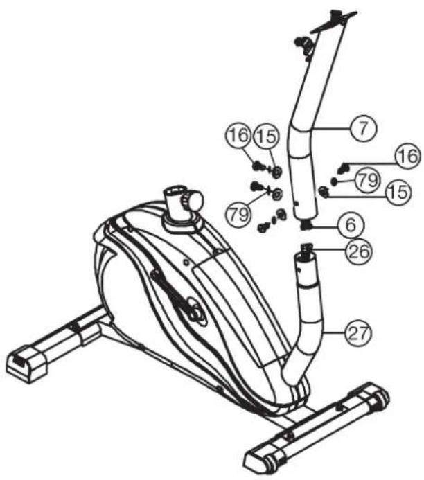
Technical diagram of a mechanical device with numbered components for identificationStep 2:
Attach the front post (7) at main frame (27).
- Hold the handlebar support (7) with the computer cable (6) Against the main frame holder. Connect the plug for the computer cable (6) coming out of the bottom of the handlebar support (7) of the computer with the matching plug for the motor cable (26) coming out of the main frame (27).
- Place the handlebar support (7) in the locator provided for it in the main frame (27). Ensure that the cable connections made are not squashed. When putting the steering tube in place, push the former slowly down into the locator in the main frame. Screw the handlebar support (7) onto the base frame (27) with the screws (16), spring washers (79) and washers (15).
text_image
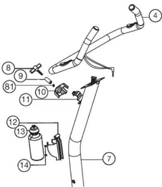
Technical diagram of a stationary exercise machine with numbered components for identificationStep 3:
Attach the handlebar (4) and bottle (13) at handlebar support (7).
- Guide the preassembled handlebar unit (4) through the upper part of the handlebar post (7) and close the bracket of handlebar holder (11).
- Attach the front handlebar cover (10) at the handlebar holder (11) of handlebar support (7) and screw the handlebar (4) in desired position at the handlebar post (7) and tighten firmly with spacer (9), washer (81) and handlebar screw (8).
- Put the bottle holder (12) at the handlebar support (7); fix it with two screws (14) at appropriate position and insert the bottle (13) into the bottle holder (12).
text_image
Technical diagram of a mechanical device with numbered components for identification and assembly reference.Step 4: Attach the computer (1) at handlebar support (7).
- Push the plug of the connecting cable (6) projecting from the handlebar support (7) into the associated socket of the computer (1).
- Place the computer on the plate provided for it on the handlebar support (7) and attach it with the screws (28).
- Push the plug of the pulse cable (5) projecting from the handlebar (4) into the associated socket of the computer (1).
Note: This computer does not have a DC connection socket, because this part you find at the rear of the side cover (see assembly step 7).

text_image
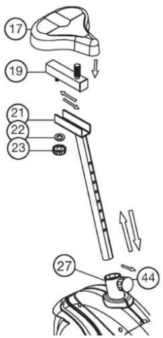
Technical diagram of a robotic arm with numbered components and labeled partsStep 5: Installation of saddle (17) at saddle support (21) by using saddle slide (19). Installation of saddle support (21) at mainframe by using rapid action lock (44).
- Push the saddle (17) with saddle bracket into the movable saddle slide (19) and tight it up in desired position.
- Place the movable seat post (19) into the holder of saddle post (21), set it at the desired horizontally position and tighten it by washer (22) and movable seat knob (23).
- Insert the saddle support (12) into the provided holder of the main frame (27) and secure at the desired position by screwing in the rapid-action lock (44).
(Note: To screw in the rapid-action lock (44), the threaded hole in the main frame (27) and one of the holes in the saddle support (21) must be aligned. Furthermore, ensure that the saddle support (21) is not pulled out of the main frame beyond the marked maximum Position. The setting of the saddle post can be adjusted as desired later. For this, the rapid action catch (44) must be loosened by only a few revolutions, the cap of the lock must be pulled away and the saddle adjusted. Then secure the new setting by tightening the rapid action catch.
text_image
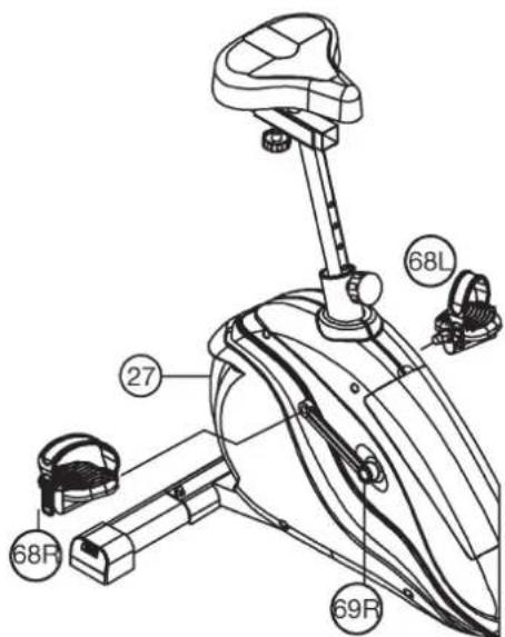
Technical diagram of a mechanical device with numbered parts and directional arrows indicating assembly or movement.Step 6: Installation of the right pedal (68R) and the left pedal (68L) on the pedal arms (69R+69L).
- The pedals are marked „R“ for right and „L“ for left.
- Screw the right pedal (68R) into the threaded hole on the right hand side of the pedal arm (69R) and tighten firmly.
(Note: Right and left are specified as viewed seated on the machine during training. It must also be observed that the threaded part of the right pedal must be screwed clockwise into the threaded hole of the pedal crank.) - Screw the left pedal (68L) into the threaded hole on the left hand side of the pedal arm (68L) and tighten firmly.
(Note: The threaded part of the left pedal must be screwed anticlockwise into the threaded hole of the pedal crank.) - Then attach the pedal straps left and right to the respective pedals.
text_image
68L 27 68R 69RStep 7: Attach the power.
- Please insert the plug of adaptor (77) to the jack of chain guard (78).
- Please insert the plug of adaptor (77) to the jack of wall power (230V-50Hz).
Step 8: Checks
- Check the correct installation and function of all screwed and plug connections. Installation is thereby complete.
- When everything is in order, familiarise yourself with the machine at a low resistance setting and make your individual adjustments.
Note:
Please keep the tool set and the instructions in a safe place as these may be required for repairs or spare parts orders becoming necessary later.
text_image
Technical line drawing of an exercise bike with numbered components and labeled partsMount, Use & Dismount
Transportation of Equipment:
There are two rollers equipped on the front foot. For moving, you can lift up the rear foot and drive it to where you would like to locate or store it.
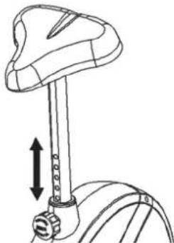
Adjustment – Seat Position
For an effective workout, the seat must be adjusted properly. While your are pedaling, your Knees should be slightly bent when the pedals are in the farthest position. In order to adjust the seat, unscrew the knob few turns and draw it out slightly. Adjust the seat to the right height, then release the knob and tighten it all the way.
natural_image
Line drawing of a bicycle suspension mechanism with arrows indicating motion direction (no text or symbols)Important:
Make sure to put the knob back into place in the seat post and tighten it completely. Never exceed the maximum height of the seat. Always get off the bicycle before making any adjustment.
Mount, Use & Dismount
Mount:
a. After the seat is adjusted to properly position, insert your foot into retaining strap of pedal step on the pedal and hold the handlebar tightly.
b. Try to put whole body weight on your foot and simultaneously cross over the trainer and land your another foot on the other side.
c. Now you are in the position to start your training.
Use:
a. Keep you hands on the handlebar, and both feet are insert into retaining straps of both pedal properly.
b. Pedal your exercise bike by your both feet alternately.
c. Then you can increase the pedaling speed gradually and adjust braking resistance levels to increase the exercise intension.
Dismount:
a. Slow down the pedaling speed until it comes to rest.
b. Keep the left hand grabbing the left handlebar tightly, put your feet cross over the equipment and land on the floor, then land the other one.
This training equipment is a stationary exercise machine used to simulate without causing excessive pressure to the joints, hence decreasing the risk of impact injuries.
Exercise bike offer a non-impact cardiovascular workout that can vary from light to high intensity based on the resistance preference set by the user. It will strengthen your muscles of legs and increase cardio capacity and maintain fitness of your body also.
Computer Instructions for 9808 C, 98081 C
text_image
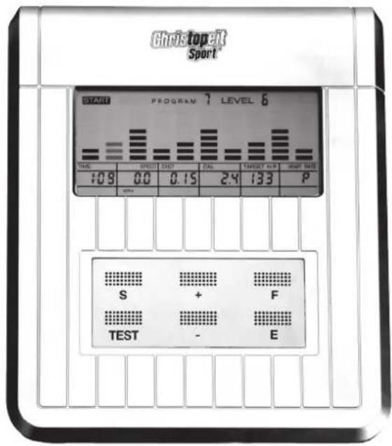
Christopelt Sport START PROGRAM 7 LEVEL 6 TIME SPEED DIST CAL TARGET NET WEIGHT 10.9 0.0 0.15 2.4 133 P S + F TEST - EThe monitor is designed for programmable magnetic bikes and introduced with the following categories:
- Key Functions
- About Displays
- Operating Ranges
- Things You Should Know Before Exercising
- Operation Instructions
• Key Functions
There are total 6 keys including START/STOP(S), ENTER/EINGABE(E), MODE/AUSWAHL(F), UP/AUF(+), DOWN/AB(-), and RECOVERY/ERHOLUNGSPULS(TEST).
A. START/STOP(S): Starts or stops the program chosen. And, resets the monitor by pressing and holding for 2 seconds.
B. ENTER(E): Chooses the functions from PROGRAMS, GENDER, TIME, HEIGHT, WEIGHT, DISTANCE, WATT, TARGET HEART RATE, AGE, and 10 columns. The chosen function shall flash. Please note that not all the functions can be selected in every program according to the types of each program.
C. MODE(F): Press this button in start mode changes the display of values between SPEED and RPM, DISTANCE and ODO and CALORIES and WATT.
D. UP(+): Selects or increases the values of PROGRAMS, GENDER, TIME, HEIGHT, WEIGHT, DISTANCE, WATT, TARGET HEART RATE, AGE, and 10 columns.
E. DOWN(-): Selects or decreases the values of PROGRAMS, GENDER, TIME, HEIGHT, WEIGHT, DISTANCE, WATT, TARGET HEART RATE, AGE, and 10 columns.
F. RECOVERY(TEST): Starts the function of PULSE RECOVERY.
- About Display
A. START
START: Indicates the program selected has started.
B. STOP
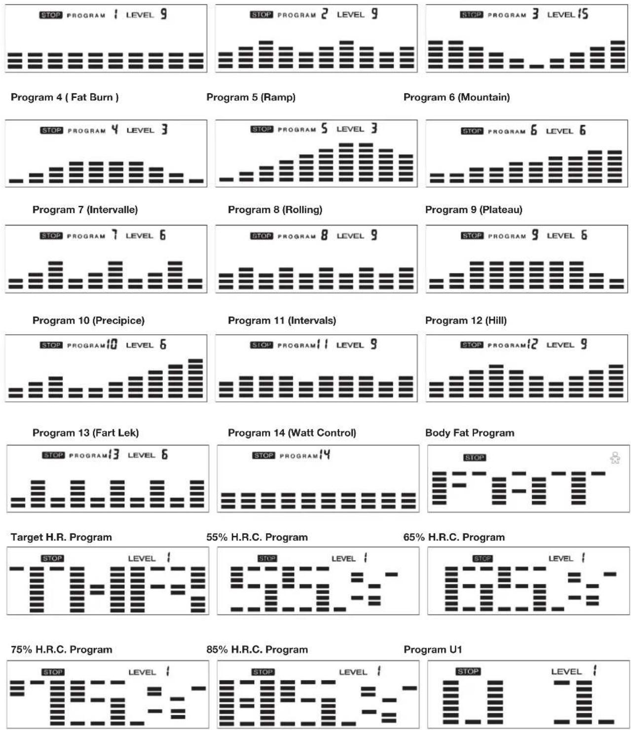
STOP: Indicates the program selected has stopped. And, users are free to change the programs and the value of functions applied.
PROGRAM 18
C.
PROGRAM: Indicates the programs selected from
PROGRAM 1 to PROGRAM 14 (24)
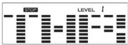
LEVEL 18
D. LEVEL: Indicates the level of loading selected from LEVEL 1 to LEVEL 24.
E.
GENDER: Indicates the gender (Male or Female) selected.
F.
TIME/HEIGHT/WEIGHT Display: Indicates only 1 value of TIME, HEIGHT, or WEIGHT displayed depending on the programs.

G. RPM/SPEED/KMH Display: Indicates only 1 value of RPM, SPEED, or KMH displayed depending on the programs.
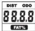
H. DISTANCE/ODO/FAT% Display: Indicates only 1 value of DISTANCE (ODO) or FAT% displayed depending on the programs.
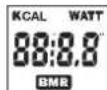
I. CAL/WATT/BMR Display: Indicates only one value of CAL, WATT, or BMR displayed depending on the programs.
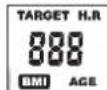
J. TARGET H.R./BMI/AGE Display: Indicates only one value of TARGET HEART RATE, BMI, or AGE displayed depending on the programs.
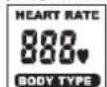
K. HEART RATE/BODY TYPE Display: Indicates only one value of HEART RATE or BODY TYPE displayed depending on the programs. L.
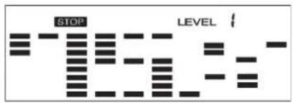
LOADING Profiles: There are 10 columns of loading bars, and 8 bars in each column. Each column represents 3 minutes workout (without the change of TIME value), and each bar represents 3 levels of loading.

natural_image
Repeating pattern of black rectangular blocks on white background (no text or symbols)- Operating Ranges
| Values | Range (Count up) | Count down | Preset | Increment (Decrement) |
| PROGRAM | 1 ~ 14 (24) | (24) 14 ~ 1 | 1 | 1 |
| LEVEL | 1 ~ 24 | 24 ~ 1 | N/A | 1 |
| GENDER | Male, Female | N/A | Male | N/A |
| TIME | 0:00 ~ 99:59 99:00 ~ 5:00 0:00 | 1:00 | ||
| HEIGHT (cm) | 110.0 ~ 199.5 | 199.5 ~ 110.0 | 175.0 | 0.5 |
| WEIGHT (kg) | 10.0 ~ 199.8 199.8 ~ 10.0 70.0 | 0.2 | ||
| DISTANCE | 0.0 ~ 999.0 | 999.0 ~ 1.0 | 0.0 | 1.0 |
| WATT | 40 ~ 250 | 250 ~ 40 | 100 | 10 |
| TARGET H.R. | 60 ~ 220 | 220 ~ 60 | 90 | 1 |
| AGE | 10 ~ 99 | 99 ~ 10 | 30 | 1 |
| CALORIES 0 ~ 9995 9995 ~ 0 0.0 | 5 | |||
- Things You Should Know Before Exercising
A. The values calculated or measured by the computer are for exercise purpose only, not for medical purpose.
B. The Variables May Need To Change In The Programs:
Please note that only 1 value of TIME or DISTANCE can be adjusted. Both adjustments do not exist at the same time. For example, the value of DISTANCE is „0.0“ while the value of TIME is adjusted to be any number except „00:00“.
C. Programs Selection:
There are totally 24 programs with 1 Recovery including 1
Manual Program, 12 Preset Programs, 1 Body Fat Program,
5 Heart Rate Control Programs, 4 User Setting Programs, 1
Speed Independent Program, and 1 Pulse Recovery Measuring.
D. Program Graph:
Each graph shown is the profile of the loading in each interval (column). With the value of TIME counting up, each interval is
3 minutes that all the columns make up 30 minutes. With the
| Programs Variables |
| P1 - P13 TIME, DISTANCE, (kcal), AGE |
| P14 TIME, DISTANCE, (kcal), WATT, AGE |
| Body Fat GENDER, HEIGHT, WEIGHT, AGE |
| Target H.R. TIME, DISTANCE, (kcal), TARGET H.R. |
| H.R.C. TIME, DISTANCE, (kcal), AGE |
| U1-U4 TIME, DISTANCE, (kcal), AGE, 10 INTERVALS |
value of TIME counting down, each interval is the value of setup TIME divided by 10. For example, if the time value is setup to 40 minutes, each interval will be 40 minutes divided by 10 intervals (40/10=4). Then, each interval will be 4 minutes. The following graphs are all the profiles in the monitor.
E. Body Types:
There are 9 body types divided according to the FAT% calculated. Type 1 is from 5% to 9%. Type 2 is from 10% to 14%. Type 3 is from 15% to 19%. Type 4 is from 20% to 24%. Type 5 is from 25% to 29%. Type 6 is from 30% to 34%. Type 7 is from 35% to 39%. Type 8 is from 40% to 44%. Type 9 is from 45% to 50%.
F. BMR: Basal Metabolism Ratio
G. BMI: Body Mass Index
Program 1 (Manual) Program 2 (Polling) Program 3 (Valley)


text_image
STOP LEVEL
text_image
STOP LEVEL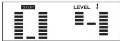
text_image
STOP LEVEL• Operation Instructions
A. Exercising With a Specific Goal:
- TIME Control: Sets up a period of time to exercise. (Except in Body Fat Program)
- DISTANCE Control: Sets up a certain distance to exercise. (Except in Body Fat Program)
- BODY FAT Control: Computer designs various programs for different people with different body fat ratio.
- WATT Control: Keeps different bodies burning in desire WATT consumed.
- Heart Rate Control: Keeps users to exercise under a safe heart-beating condition
B. Pulse Rate:
The whole set of heart rate detector include 2 sensors each side. Each sensor has 2 pieces of metal parts. The correct way to get detected is to gently hold both metal parts each hand. With the good signals picked up by the computer, the heart mark in the HEART RATE/BODY TYPE Display shall flash.
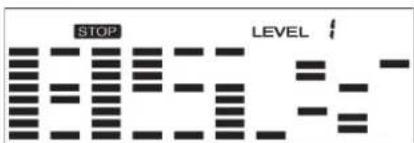
C. I Program:
PROGRAM 1 is a manual program. Press „ENTER“ key to select TIME, DISTANCE, and AGE. Then, press(+) or (-) key to adjust the values. The default level of loading is 6. After pressing „START/STOP“ key to exercise, please also apply the heart rate detector appropriately. Users may exercise in any desire level (by pressing (+) or (-) during the workout) with a period of time or a certain distance. With the input of age, the computer may suggest a target heart rate to exercise. The suggested heart rate is 85%(220 – age). So, if the heart rate detected equals to or greater than the TARGET H.R., the value of HEART RATE will keep flashing. Please note that it is a warning for users to slow down or to lower the level of loading.
D. Preset Programs:
PROGRAM 2 to PROGRAM 13 are the preset programs. Press "ENTER" key to select TIME, DISTANCE, and AGE. Then, press (+) or (-) key to adjust the values. Users may exercise with different level of loading in different intervals as the profiles show. After pressing "START/STOP" key to exercise, please also apply the heart rate detector appropriately. Users may also exercise in any desire level (by pressing (+) or (-) during the workout) with a period of time or a certain distance. With the input of age, the computer may suggest a target heart rate to exercise. The suggested heart rate is 85%(220 - age). So, if the heart rate detected equals to or greater than the TARGET H.R., the value of HEART RATE will keep flashing. Please note that it is a warning for users to speed down or to lower the level of loading.
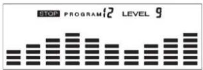
E. Speed Independent Program:
Program 14 is a Speed Independent Program. Press „ENTER“ key to select the values of TIME, DISTANCE, WATT, and AGE. Then, press (+) or (-) key to adjust the values. After pressing „START/STOP“ key to exercise, please also apply the heart rate detector appropriately. During the exercise, the level of loading is not adjustable. In this program, computer will adjust the level of loading according to the value of WATT setup. For example, the level of loading may increase while the speed is too slow. Also, the level of loading may decrease while the speed is too fast. As a result, the calculated value of WATT will close to the value of WATT setup by users. With the input of age, the computer may suggest a target heart rate to exercise. The suggested heart rate is 85%(220 - age). So, if the heart rate detected equals to or greater than the TARGET H.R., the value of HEART RATE will keep flashing. Please note that it is a warning for users to speed down or to lower the level of loading.
F. Body Fat Program:
This is a special program designed to calculate users' body fat ratio and to design a specific loading profile for users. With 9 different body types, the computer can generate 9 different
profiles for each. Press „ENTER“ key to select GENDER, HEIGHT, WEIGHT, and AGE. Then, press (+) or (-) key to adjust the values. After pressing „START/STOP“ key to calculate body fat, please also apply the heart rate detector appropriately. If the detector cannot pick up any signals, an error message „E4“ will show up in the profile display. If it happens, press „START/STOP“ key to calculate again. Then, the calculation values of FAT%, BMR, BMI, BODY TYPE will show up shortly.
G. Heart Rate Control Programs:
These Program 16 to Program 20 are the Heart Rate Control Programs. In program T.H.R. Program, press „Enter“ key to select TIME, DISTANCE, and TARGET H.R. Users may setup a target heart rate to exercise in a period of time or a certain distance. In H.R.C. Programs press „Enter“ key to select TIME, DISTANCE, and AGE. Then, press (+) or (-) key to adjust the values. Users may exercise in a period of time or a certain distance with 55% Max Heart Rate Program, 65% Max Heart Rate Program, 75% Max Heart Rate Program and 85% Max Heart Rate Program. After pressing „START/STOP“ key to exercise, please also apply the heart rate detector appropriately. In these programs, the computer will adjust the level of loading according to the heart rate detected. For example, the level of loading may increase while the heart rate detected is lower than TARGET H.R. Also, the level of loading may decrease while the heart rate detected is higher than TARGET H.R. As a result, the user's heart rate will be adjusted to close the TARGET H.R. in the range of TARGET H.R. -5 and TARGET H.R. +5.
H. User Setting Programs:
U1-U4 are the user-setting programs. Users are free to edit the values in the order of TIME, DISTANCE, AGE, and the level of loading in 10 intervals. The values and profiles will be stored in the memory after setup. After pressing „START/STOP“ key to exercise, please also apply the heart rate detector appropriately. Users may also change the ongoing loading in each interval by pressing (+) or (-) key, and they will not change the level of loading stored in the memory. With the input of age, the computer may suggest a target heart rate to exercise. The suggested heart rate is 85%(220 – age). So, if the heart rate detected equals to or greater than the TARGET H.R., the value of HEART RATE will keep flashing. Please note that it is a warning for users to speed down or to lower the level of loading.
I. Pulse Recovery (TEST):
It is a function to check the condition of pulse recovery that is scaled from 1.0 to 6.0 while 1.0 means the best and 6.0 means the worst and the increment is 0.1. In order to get rated correctly, users must test it right after the workout finished by pressing „RECOVERY“ key and then stop exercising. After the key is pressed, please also apply the heart rate detector appropriately. The test will last for 1 minute and the result will show in the display.
Cleaning, Checks and Storage of the Ergometer bike:
1. Cleaning
Use only a less wet cloth for cleaning. Caution: Never use benzene, thinner or other aggressive cleaning agents for surface cleaning as this damage caused.
The device is only for private home use and for use suitable indoors. Keep the unit clean and moisture from the device.
2. Storage
Plug out the power supply unit while intending the unit for more than 4 weeks not to use. Push the saddle slide toward the handlebar and the seat support tube as deeply as possible into the frame. Choose a dry storage in-house and put some spray oil to the pedal bearings left and right, to the thread of the handlebar bolt, and on the thread of the quick release for saddle support.
Cover the bike to protect it from being discolor by any sunlight and dirty through dust.
3. Checks
We recommend every 50 hours to review the screw connections for tightness, which were prepared in the assembly. Every 100 operating hours, you should put some spray oil at the pedal bearings left and right, to the thread of the handlebar bolt and to the thread of quick release for saddle support.
Troubleshooting
If you cannot solve the problem with the following information, please contact the authorized service center.
| Problem Possible | Cause Solution | |
| Computer has no value at Display if you press any key. | No power adapter is well plugged or wall power is without power. | Check that the power adapter is properly plugged in, possibly with another electric device check if the wall power is fine. |
| Computer is not counting data and do not switch on after start cycling. | Sensor impulse missing base on not well plugged connection | Check the plug connections at computer and inside of handle-bar support. |
| Computer is not counting data and do not switch on after start cycling. | Sensor impulse missing base on not correct position of sensor. | Take off the cover and check the distance between magnet and Sensor. The magnet at turning belt wheel should have only less than < 5mm distance against the sensor position. |
| No pulse value Pulse | use cable is not plugged in. | Check the separately pulse cable is well connected with computer. |
| No pulse value Pulse | use sensors not well connected | Screw out the screw for pulse measurement and check if plugs are well connected and no damage at pulse cable. |
Training area in mm (for home trainer and user)
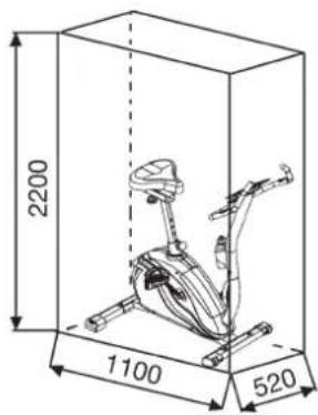
text_image
2200 1100 520Free area in mm
(Training area and security area
(rotating 60cm))

text_image
2300 1720 2200Training instructions
You must consider the following factors in determining the amount of training effort required in order to attain tangible physical and health benefits:
1. Intensity:
The level of physical exertion in training must exceed the level of normal exertion without reaching the point of breathlessness and / or exhaustion. A suitable guideline for effective training can be taken from the pulse rate. During training this should rise to the region of between 70% to 85% of the maximum pulse rate (see the table and formular for determination and calculation of this).
During the first weeks, the pulse rate should remain at the lower end of this region, at around 70% of the maximum pulse rate. In the course of the following weeks and months, the pulse rate should be slowly raised to the upper limit of 85% of the maximum pulse rate. The better the physical condition of the person doing the exercise, the more the level of training should be encreased to remain in the region of between 70% to 85% of the maximum pulse rate. This should be done by lengthening the time for the training and / or encreasing the level of difficulty.
If the pulse rate is not shown on the computer display or if for safety reasons you wish to check your pulse rate, which could have been displayed wrongly due to error in use, etc., you can do the following:
a. Pulse rate measurement in the conventional way (feeling the pulse at the wrist, for example, and counting the number of beats in one minute).
b. Pulse rate measurement with a suitable specialised device (available from dealers specialising in health-related equipment).
2.Frequency
Most experts recommend a combination of health-conscious nutrition, which must be determined on the basis of your training goal, and physical training three times a week. A normal adult must train twice a week to maintain his current level of condition. At least three training sessions a week are required to improve one's condition and reduce one's weight. Of course the ideal frequency of training is five sessions a week.
3. Planning the training
Each training session should consist of three phases: the warm-up phase, the training phase, and the cool-down phase. The body temperature and oxygen intake should be raised slowly in the warm-up phase. This can be done with gymnastic exercises lasting five to ten minutes.
Then the actual training (training phase) should begin. The training exertion should be relatively low for the first few minutes and then raised over a period of 15 to 30 minutes such that the pulse rate reaches the region of between 70% to 85% of the maximum pulse rate.
In order to support the circulation after the training phase and to prevent aching or strained muscles later, it is necessary to follow the training phase with a cool-down phase. This should be consist of stretching exercises and / or light gymnastic exercises for a period of five to ten minutes.
You find further information on the subject warm-up exercises, stretch exercises or general gymnastics exercises in our download area under www.christopeit-sport.com
4. Motivation
The key to a successful program is regular training. You should set a fixed time and place for each day of training and prepare yourself mentally for the training. Only train when you are in the mood for it and always have your goal in view. With continuous training you will be able to see how you are progressing day by day and are approaching your personal training goal bit by bit.

line
| X-axis | Maximalpuls (220-After) Maximum pulse rate (220-age) | 90% des Maximalpulses 90% of the maximum pulse rate | 85% des Maximalpulses 85% of the maximum pulse rate | 70% des Maximalpulses 70% of the maximum pulse rate | |---|---|---|---|---| | 20 | 200 | 180 | 170 | 140 | | 25 | 195 | 175 | 165 | 136 | | 30 | 190 | 171 | 161 | 133 | | 35 | 185 | 166 | 157 | 129 | | 40 | 180 | 162 | 153 | 126 | | 45 | 175 | 157 | 148 | 122 | | 50 | 170 | 153 | 144 | 119 | | 55 | 165 | 148 | 140 | 115 | | 60 | 160 | 144 | 136 | 112 | | 65 | 155 | 139 | 131 | 108 | | 70 | 150 | 135 | 127 | 105 |Calculation formula: Maximum pulse rate = 220 - age
(220 minus your age)
90% of the maximum pulse rate = (220 - age) x 0.9
85% of the maximum pulse rate = (220 - age) x 0.85
70% of the maximum pulse rate = (220 - age) x 0.7
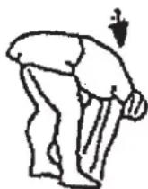
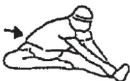
Warm up exercises (Warm Up)
Start your warm up by walking on the spot for at least 3 minutes and then perform the following gymnastic exercises to the body for the training phase to prepare accordingly. The exercises do not overdo it and only as far run until a slight drag felt. This position will hold a while.

natural_image
Simple line drawing of a person in a kneeling position with an arrow indicating motion (no text or symbols)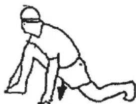
natural_image
Line drawing of a person in a kneeling or stretching pose (no text or symbols)Reach with your left hand behind your head to the right shoulder and pull with the right hand slightly to the left elbow. After 20sec. switch arm.
Bend forward as far forward as possible and let your legs almost stretched. Show it with your fingers in the direction of toe. 2 x 20sec.
Sit down with one leg stretched out on the floor and bend forward and try to reach the foot with your hands. 2 x 20sec.
Kneel in a wide lunge forward and support yourself with your hands on the floor. Press the pelvis down. Change after 20 sec leg.
F
Sommaire
text_image
Technical diagram of a mechanical device with numbered components and assembly linesEtape n° 2:
text_image
Technical diagram of a stationary exercise machine with numbered components for identificationEtape n° 3:
text_image
Technical diagram of a mechanical device with numbered components for identificationEtape n° 4:
text_image
Technical diagram of a robotic arm with numbered components and directional arrows indicating movement or assembly.Etape n° 5:
text_image
Technical diagram of a mechanical device with numbered parts and directional arrows indicating motion or assembly.Etape n° 6:
text_image
Technical line drawing of an exercise bike with numbered components and labeled partsMonter, utiliser & descendre
natural_image
Line drawing of a bicycle steering wheel with a vertical guide and upward arrow indicating motion (no text or symbols)natural_image
Simple line drawing of a person in a kneeling or stretching pose with an arrow indicating motion (no text or symbols)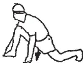
natural_image
Line drawing of a person in a kneeling position with a headband and motion arrow (no text or symbols)text_image
Technical diagram of a mechanical device with numbered components, likely an exercise or assembly assembly.Stap 2:
text_image
Technical diagram of a stationary exercise machine with numbered component labelsStap 3:
text_image
Technical diagram of a mechanical device with numbered components for identificationStap 4: Montage van de computer (1).
text_image
Technical diagram of a robotic arm with numbered components and labeled partstext_image
Technical diagram of a mechanical device with numbered parts and directional arrows indicating assembly or movement.Stap 6: Montage van de pedalen (68L+68R).
text_image
Technical line drawing of an exercise bike with numbered components and labeled partsnatural_image
Line drawing of a mechanical device with a lever and adjustment arrow (no text or symbols)Belangrijk:
text_image
STOP F- F- F- TProgramma beoogde polsslag
text_image
STOP LEVELProgramma 55% max. polsslag Programma 65% max. polsslag

text_image
STOP LEVEL i 515-
text_image
STOP LEVEL 1 EELProgramma 75% max. polsslag
text_image
STOP LEVELProgramma 85% max. polsslag

text_image
STOP LEVELtext_image
STOP LEVELtext_image
STOP LEVELProgramma's 2 -13: fitness
3. Planning van de training
natural_image
Simple line drawing of a person in a kneeling or stretching pose with an arrow indicating motion (no text or symbols)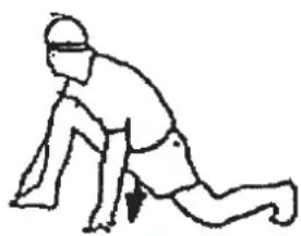
natural_image
Line drawing of a person in a kneeling position with a downward arrow indicating motion (no text or symbols)text_image
Technical diagram of a stationary exercise machine with numbered components for identificationWar 3:
text_image
Technical diagram of a mechanical device with numbered components for identification and assembly reference.text_image
Technical diagram of a robotic arm with numbered components and directional arrows indicating movement or assembly.text_image
Technical diagram of a mechanical device with numbered parts and directional arrows indicating assembly or movement.text_image
Technical line drawing of an exercise bike with numbered components and labeled partsnatural_image
Diagram of a bicycle steering wheel with a vertical guide and directional arrows indicating motion (no text or labels)Важно:
text_image
STOP PROGRAM#1 LEVEL 9Programm 14 (Batt)
text_image
STOP PROGRAM12 LEVEL 9text_image
STOP F- F- F- Ttext_image
STOP LEVELtext_image
STOP LEVELПользователь U2
text_image
STOP LEVELПользователь U3
text_image
STOP LEVELПользователь U4
text_image
STOP LEVEL
text_image
STOP LEVEL
text_image
STOP LEVEL 1Программа 1: Ручная
natural_image
Simple line drawing of a person in a kneeling position with an arrow indicating motion (no text or symbols)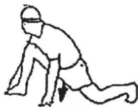
natural_image
Line drawing of a person in a kneeling position with a downward arrow indicating motion (no text or symbols)text_image
top Sports© by Top-Sports Gilles GmbH D-42551 Velbert (Germany)