EM 5 - Exercise bike Christopeit - Free user manual and instructions
Find the device manual for free EM 5 Christopeit in PDF.

User questions about EM 5 Christopeit
0 question about this device. Answer the ones you know or ask your own.
Ask a new question about this device
Download the instructions for your Exercise bike in PDF format for free! Find your manual EM 5 - Christopeit and take your electronic device back in hand. On this page are published all the documents necessary for the use of your device. EM 5 by Christopeit.
USER MANUAL EM 5 Christopeit
natural_image
Woman exercising on a stationary exercise bike (no visible text or symbols)
Assembly and exercise instructions for Order No. 9803

text_image
Technical diagram of a stationary exercise machine with numbered components for identification and assembly reference.
text_image
Technical diagram of a mechanical assembly with numbered components and exploded viewstext_image
Technical diagram showing labeled mechanical components with numbered parts for identificationSchritt 3:
text_image
Technical diagram of a mechanical assembly with numbered components for identificationSchritt 4:
text_image
Technical diagram of a mechanical device with numbered components and labeled partsSchritt 5:
text_image
Technical diagram of a mechanical assembly with numbered components, likely for engineering or manufacturing documentation.Schritt 6:
text_image
Technical diagram of a mechanical assembly with numbered components, likely for assembly or maintenance instructions.Schritt 7:
text_image
Technical diagram showing labeled mechanical components with numbered parts 1, 12, 13, and 14Schritt 8:
text_image
Technical diagram of a mechanical linkage system with numbered components and dashed lines indicating connectionsSchritt 9:
text_image
Technical diagram of a mechanical component with numbered parts and directional arrows indicating assembly or movement.Schritt 10:
text_image
Technical diagram of a stationary exercise machine with numbered components for identificationSchritt 11:
text_image
Technical diagram of a mechanical device with numbered components, likely an optical or sensor assembly.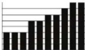
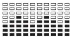
hoher Balken = hoher Tretwiderstand
Programme 2 -7: FitnessFitness
text_image
ECEO PROCEAM 18 LEVEL 18 TEST E E START STOP F Christ's Europe Sport®Garantiebestimmungen
- Summary of Parts Page 3 - 4
- Important Recommendations and Safety Information Page 14
- Parts List Page 15 - 16
- Assembly Instructions With Exploded Diagrams Page 17 - 19
- Computer instructions Page 20 - 22
- Training Instructions Page 22
Dear customer,
We congratulate you on your purchase of this home training sports unit and hope that we will have a great deal of pleasure with it. Please take heed of the enclosed notes and instructions and follow them closely concerning assembly and use.
Please do not hesitate to contact us at any time if you should have any questions.
Important Recommendations and Safety Instructions
Our products are all TÜV-GS tested and therefore represent the highest current safety standards. However, this fact does not make it unnecessary to observe the following principles strictly.
-
Assembly the machine exactly as described in the installation instructions and use only the enclosed, specific parts of the machine contained in the parts list. Before assembling, verify the completeness of the delivery against the delivery notice and the completeness of the carton against the parts list in the installation and operating instructions.
-
Check the firm seating off all screws, nuts and other connections before using the machine for the first time and at regular intervals to ensure that the trainer is in a safe condition.
-
Set up the machine in a dry, level place and protect it from moisture and water. Uneven parts of the floor must be compensated by suitable measures and by the provided adjustable parts of the machine if such are installed. Ensure that no contact occurs with moisture or water.
-
Place a suitable base (e.g. rubber mat, wooden board etc.) beneath the machine if the area of the machine must be specially protected against indentations, dirt etc.
-
Before beginning training, remove all objects within a radius of 2 metres from the machine.
-
Do not use aggressive cleaning agents to clean the machine and employ only the supplied tools or suitable tools of your own to assemble the machine and for any necessary repairs. Remove drops of sweat from the machine immediately after finishing training.
-
Your health can be impaired by incorrect or excessive training. Consult a doctor before beginning a planned training programme. He can define the maximum exertion (pulse, Watts, duration of training etc.) to which you may expose yourself and can give you precise information on the correct posture during training, the targets of your training and your diet. Never train after eating large meals. Observe that this machine is not suitable for therapeutic purposes.
-
Only train on the machine when it is in correct working order. Use original spare parts only for any necessary repairs.
-
When setting the adjustable parts, observe the correct position and the marked, maximum setting positions and ensure that the newly adjusted position is correctly secured.
-
Unless otherwise described in the instructions, the machine must only be used for training by one person at a time.
-
Wear training clothes and shoes which are suitable for fitness training with the machine. Your clothes must be such that they cannot catch during training due to their shape (e.g. length). Your training shoes should be appropriate for the trainer, must support your feet firmly and must have non-slip soles.
- If you notice a feeling of dizziness, sickness, chest pain or other abnormal symptoms, stop training and consult a doctor.
- Never forget that sports machines are not toys. They must therefore only be used according to their purpose and by suitably informed and instructed persons.
- People such as children, invalids and handicapped persons should only use the machine in the presence of another person who can give aid and advice. Take suitable measures to ensure that children never use the machine without supervision.
- Ensure that the person conducting training and other people never move or hold any parts of their body into the vicinity of moving parts.
- At the end of its life span this product is not allowed to dispose over the normal household waste, but it must be given to an assembly point for the recycling of electric and electronic components. You may find the symbol on the product, on the instructions or on the packing. The materials are reusable in accordance with their marking. With the reuse, the material utilization or the protection of our environment. Please ask the local administration for the responsible disposal place.
- This machine is a speed-dependant machine, i.e. the power increases with increasing speed, and the reverse.
- The machine is equipped with 16-speed resistance adjustment. This makes it possible to reduce or increase the braking resistance and thereby the training exertion. Pressing the button “-” for the resistance setting towards stage 1 reduces the braking resistance and thereby the training exertion. Pressing the button “+” for the resistance setting towards stage 16 increases the braking resistance and thereby the training exertion.
- This machine has been tested and certified in compliance with EN 957-1 and -5 "H. C". The maximum permissible load (=body weight) is specified as 130 kg.
Parts list – List of spare parts
EM 5 order No. 9803
Technical data: As of: 01. 03. 2006
Home trainer with Ergometer-Functions
Motor-controlled magnetic brake system
Approx. 9 kg centrifugal mass
6 stored training programs (graphic depiction)
4 stored heart rate programs (pulse controlled)
4 manually programs, 16 adjustable resistance load steps
1 body fat program
Display of Watt
Hand pulse measurement
Horizontally and vertically adjustable saddle
Saddle and handlebar inclination adjustable
Saddle universal exchangeable
Floor level compensation
Transport rollers at front foot
Easy to use, 6-window computer with concurrent display of:
Time, speed, distance, pedal revolutions per minute, pulse frequency, maximum
pulse rate (age-dependent), watt, approx. calory consumption and body fat
analyse
Input of limits such as time, distance, approx. calory consumption and upper
pulse frequency. Exceeded limits are displayed.
Load max. 130 kg (Body weight)
Space requirement approx. L 90 x B 50 x H 135 cm
Please check after opening the packing that all the parts shown in the following parts lists are there. Once you are sure that this is the case, you can start assembly.
Please contact us if any components are defective or missing, or if you need any spare parts or replacements in future:
Assembly instructionsAssembly instructions
Step 1:
Remove all the separate parts from the packaging, lay them on the floor and check that all are there on the basis of the packing list in these instructions for assembly and use. Please note that a number of parts have been connected directly to the main frame and preassembled. In addition, there are several other individual parts that have been attached to separate units. This will make it easier and quicker for you to assemble the equipment.
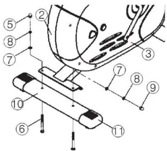
Step 2:
Attach the front foot (4) with the preassembled transport rollers (5) to the main frame. Do this with the two screws (6), washers (7), spring washers (8) and locking nuts (9).

text_image
Technical diagram of a mechanical device with numbered components and alignment linesStep 3:
Attach the rear foot (10) with the preassembled end caps (11) to the main frame. Do this with the two screws (6), washers (7), spring washers (8) and locking nuts (9).
After assembly has been completed, you can compensate for minor irregularities in the floor by turning the two adjusting screw (34). The equipment should be set up that the equipment does not move of its own accord during a training session.
text_image
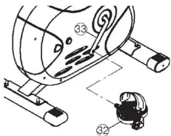
Technical diagram of a mechanical assembly with numbered components for identificationStep 4:
Screw the right pedal (32) into the locator in the right-hand side (as seen in operation) for the pedal crank (33) (warning! the screw direction is clockwise). Screw the left pedal (32a) into the locator in the left-hand side (as seen in operation) for the pedal crank (33) (warning! the screw direction is anti-clockwise).
Then mount the pedal straps left and right on the associated pedals.
text_image
Technical diagram of a mechanical device with numbered components, likely illustrating a gear or cam mechanism.Step 5:
Push the saddle (20) with saddle bracket (21) into the movable seat post (22) and tight it up in desired position. Place the movable seat post (22) into the holder of saddle post (18), set it at the desired position and screw it onto the fix plate (40) by washer (23) and movable seat post knob (24).

text_image
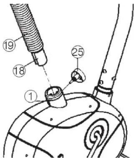
Technical diagram of a mechanical assembly with numbered components, likely for engineering or manufacturing documentation.Step 6:
Push the saddle support tube sleeve (19) over the saddle support tube (18).
Place the seat pillar (18) into the matching locator in the main frame (1), set it at the desired position and lock it by inserting the bolt with the knurled grip (25) in place and doing it up tight.
Take care when doing this, to ensure correct installation, that one of the holes of the seat pillar (18) lines up with the threaded hole in the main frame used for the bolt with the knurled grip (25).
Furthermore, you must ensure when setting this desired position that the seat pillar is not pulled out of the main frame further than the highest setting position "A", which is marked in colour.
text_image
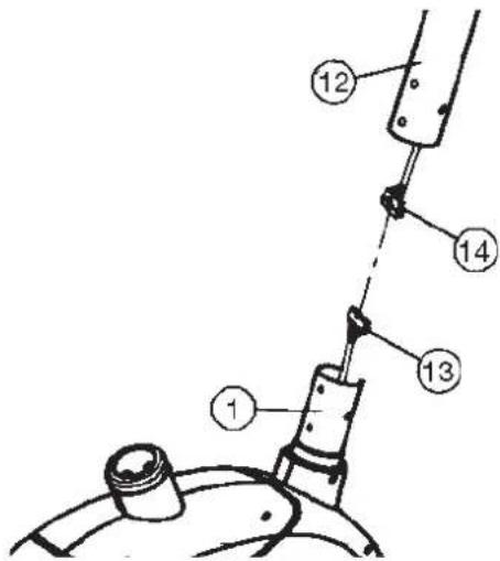
Technical diagram of a mechanical component with numbered parts and labeled partsStep 7:
Hold the steering tube (12) with the computer wiring loom (14) already in place in it. Connect the plug for the computer wiring loom (14) coming out of the bottom of the steering tube (12) of the computer with the matching plug for the computer wiring loom (13) coming out of the main frame (1).
text_image
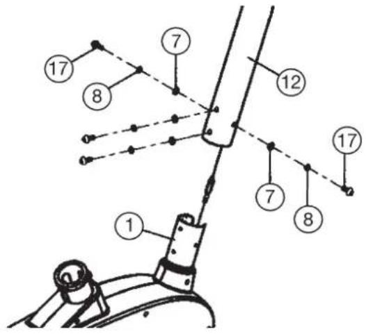
Technical diagram of a mechanical assembly with numbered components labeled 1, 12, 13, and 14Step 8:
Place the steering tube (12) in the locator provided for it in the main frame (1). Ensure that the cable connections made in step 8 are not squashed. When puttin the steering tube in place, push the former slowly down into the locator in the main frame. Screw the handlebar upright tube (12) onto the base frame (1) with the screws (17), spring washers (8) and washers (7).
text_image
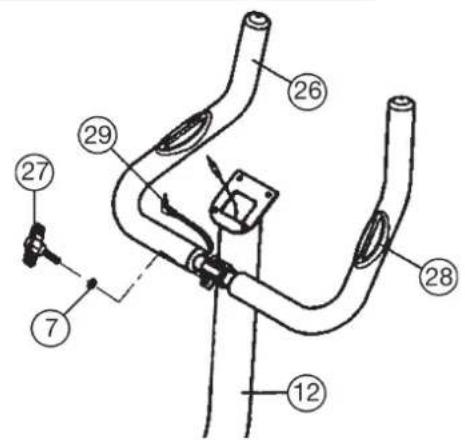
17 8 7 12 7 8 17 1Step 9:
Guide the preassembled handlebar unit (26) through the upper part of the handlebar post (12) and close the bracket of handlebar holder. Screw the handlebar (26) in desired position at the handlebar post (12) with washer (7) and handlebar screw (27).
text_image
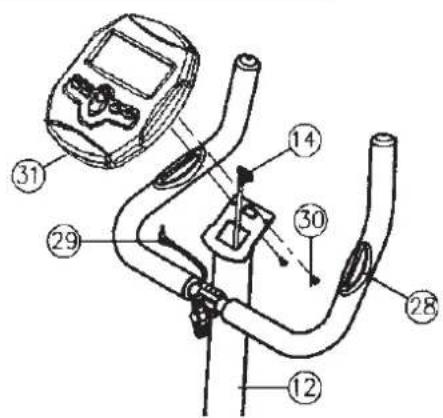
Technical diagram of a mechanical component with numbered parts and labeled partsStep 10:
Place the computer on the plate provided for it on the handlebar upright tube (12) and attach it with the screws (30). Push the computer onto the provided plate on the handlebar support tube (12). Push the plug of the cable harness (29) projecting from the handlebar unit into the associated socket of the computer (31).
text_image
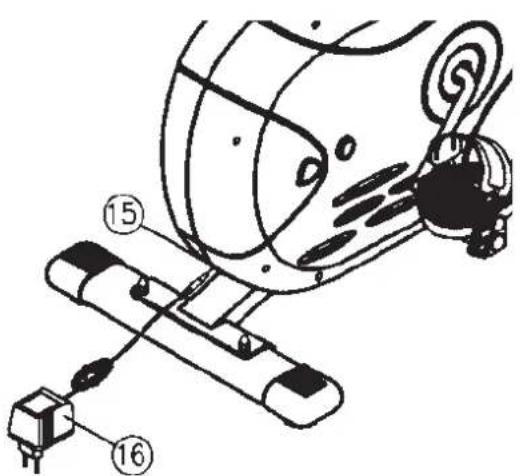
Technical diagram of a stationary bike with numbered parts for identificationStep 11:
Attach the power
- Please insert the plug of adaptor (16) to the jack (15) of chain guard.
- Please insert the plug of adaptor (16) to the jack of wall power.
Step 12:
Checks
- Check the correct installation and function of all screwed and plug connections.
Installation is thereby complete. - When everything is in order, familiarise yourself with the machine at a low resistance setting and make your individual adjustments.
Note:
Please keep the tool set and the instructions in a safe place as these may be required for repairs or spare parts orders becoming necessary later.
text_image
Technical diagram of a mechanical device with numbered components, likely an electrical or mechanical assembly.Computer instruction for 9803 Computer instruction for 9803
The monitor is designed for programmable magnetic bikes and introduced with the following categories:
| - | K | e | y | F | u | n | c | t | i | o | n | s | ||
| - | A | b | o | u | t | D | i | s | p | l | a | y | s | |
| - | O | p | e | r | a | t | i | n | g | R | a | n | g | |
| - | T | h | i | n | g | s | Y | o | u | S | h | o | ||
| - | O | p | e | r | a | t | i | o | n | l | n | s | t |
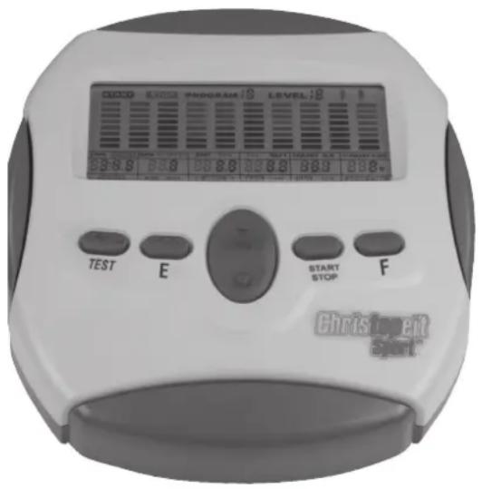
• K e y F u n c t i o n
There are total 6 keys including START/STOP, ENTER, MODE, UP, DOWN, and RECOVERY.
A. START/STOP: Starts or stops the program chosen. And, resets the monitor by pressing and holding for 2 seconds.
B. ENTER (E): Chooses the functions from PROGRAMS, GENDER, TIME, HEIGHT, WEIGHT, DISTANCE, WATT, TARGET HEART RATE, AGE, and 10 columns. The chosen function shall flash. Please note that not all the functions can be selected in every program according to the types of each program.
C. MODE (F): Changes the displays of the values between RPM or SPEED, and KJOULE/CAL or WATT. The values of RPM and WATT show at the same time, or the values of SPEED and KJOULE/CAL do by pressing it.
D. UP (▲): Selects or increases the values of PROGRAMS, GENDER, TIME, HEIGHT, WEIGHT, DISTANCE, WATT, TARGET HEART RATE, AGE, and 10 columns.
E. DOWN (▼): Selects or decreases the values of PROGRAMS, GENDER, TIME, HEIGHT, WEIGHT, DISTANCE, WATT, TARGET HEART RATE, AGE, and 10 columns.
F. RECOVERY (TEST): Starts the function of PULSE RECOVERY.
• A b o u t D i s p l a
A.
START
START: Indicates the program selected has started.
STOP
B.
STOP: Indicates the program selected has stopped. And, users are free to change the programs and the value of functions applied.
PROGRAM 18
PROGRAM çö: Indicates the programs selected from PROGRAM 1 to PROGRAM 15 (or 17).
LEVEL 18
LEVELcö: Indicates the level of loading selected from LEVEL 1 to LEVEL 16.
[Non-Text]
E.
GENDER: Indicates the gender (Male or Female) selected.
F.
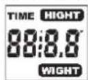
TIME/HEIGHT/WEIGHT Display: Indicates only 1 value of TIME, HEIGHT, or WEIGHT displayed depending on the programs.
G.
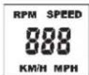
RPM/SPEED/KMH (MPH) Display: Indicates only 1 value of RPM, SPEED, or KMH (MPH) displayed depending on the programs.
H.
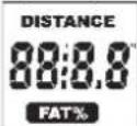
DISTANCE/FAT% Display: Indicates only 1 value of DISTANCE or FAT% displayed depending on the programs.
instruction for 9803
CAL/WATT/BMR Display: Indicates only one value of CAL, WATT, or BMR displayed depending on the programs.
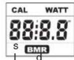
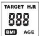
TARGET H.R./BMI/AGE Display: Indicates only one value of TARGET HEART RATE, BMI, or AGE displayed depending on the programs.
K.
HEART RATE/BODY TYPE Display: Indicates only one value of HEART RATE or BODY TYPE displayed depending on the programs.

L.
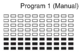
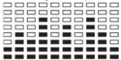
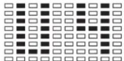
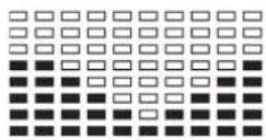
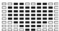
LOADING Profiles: There are 10 columns of loading bars, and 8 bars in each column. Each column represents 3 minutes workout (without the change of TIME value), and each bar represents 2 levels of loading.

natural_image
Grid of black rectangular blocks with no text or symbols•
Operating Ranges
| Values | Range (Count up) | Count down | Preset | Increment (Decrement) |
| PROGRAM | 1 ~ 16 | 16 ~ 1 | 1 | 1 |
| LEVEL | 1 ~ 16 | 16 ~ 1 | N/A | 1 |
| GENDER | Male, Female | N/A | Male | N/A |
| TIME | 0:00 ~ 99:59 | 99:00 ~ 5:00 | 0:00 | 1:00 |
| HEIGHT (cm) | 110.0 ~ 199.5 | 199.5 ~ 110.0 | 175.0 | 0.5 |
| WEIGHT (kg) | 10.0 ~ 199.8 | 199.8 ~ 10.0 | 70.0 | 0.2 |
| DISTANCE | 0.0 ~ 999.0 | 999.0 ~ 1.0 | 0.0 | 1.0 |
| TARGET H.R. | 60 ~ 220 | 220 ~ 60 | 90 | 1 |
| AGE | 10 ~ 99 | 99 ~ 10 | 30 | 1 |
• Things You Should Know Before Exercising
A. The values calculated or measured by the computer are for exercise purpose only, not for medical purpose. B. The Variables May Need To Change In The Programs:
| Programs | Variables |
| P1 ~ P7 | TIME, DISTANCE, AGE |
| P8 | GENDER, HEIGHT, WEIGHT, AGE |
| P9 | TIME, DISTANCE, TARGET H.R. |
| P10 ~ P12 | TIME, DISTANCE, AGE |
| P13 ~ P16 | TIME, DISTANCE, AGE, 10 Intervals |
Please note that only 1 value of TIME or DISTANCE
can be adjusted. Both adjustments do not exist at the same time. For example, the value of DISTANCE is „0.0“ while the value of TIME is adjusted to be any number except „00:00“.
C. Programs Selection:
There are 16 programs including 1 Manual Program, 6 Preset Programs, 1 Body Fat Program, 4 Heart Rate Control Programs, 4 User Setting Programs, and 1 Pulse Recovery Measuring.
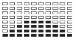
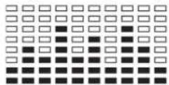
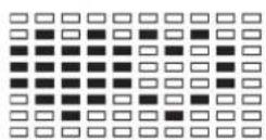
D. Program Graph:
Each graph shown is the profile of the loading in each interval (column). With the value of TIME counting up, each interval is 3 minutes that all the columns make up 30 minutes. With the value of TIME counting down, each interval is the value of setup TIME divided by 10. For example, if the time value is setup to 40 minutes, each interval will be 40 minutes divided by 10 intervals (40/10=4). Then, each interval will be 4 minutes. The following graphs are all the profiles in the monitor.
text_image
Program 1 (Manual)Program 2 (Polling)

Program 3 (Valley)

Program 4 (Fat Burn)
Program 5 (Ramp)

Program 6 (Mountain)

Program 7 (Random)
Program 8 (Body Fat)

Program 9 (Target H.R.)

Program 10 (60% H.R.C.)
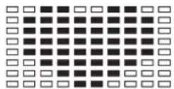
Program 11 (75% H.R.C.)

Program 12 (85% H.R.C.)

Program 13 (User Setting)

Program 14 (User Setting)
Program 15 (User Setting)
Program 16 (User Setting)
E. Body Types:
There are 9 body types divided according to the FAT% calculated. Type 1 is from 5% to 9%. Type 2 is from 10% to 14%. Type 3 is from 15% to 19%. Type 4 is from 20% to 24%. Type 5 is from 25% to 29%. Type 6 is from 30% to 34%. Type 7 is from 35% to 39%. Type 8 is from 40% to 44%. Type 9 is from 45% to 50%.
F. BMR: Basal Metabolism Ratio
G. BMI: Body Mass Index
• O p e r a t i o n l n s
A. Exercising With a Specific Goal:
- TIME Control: Sets up a period of time to exercise. (Except in Program 8)
- DISTANCE Control: Sets up a certain distance to exercise. (Except in Program 8)
- BODY FAT Control: Computer designs various programs for different people with different body fat ratio.
- Heart Rate Control: Keeps users to exercise under a safe heart-beating condition
B. Pulse Rate:
The whole set of heart rate detector include 2 sensors each side. Each sensor has 2 pieces of metal parts. The correct way to get detected is to gently hold both metal parts each hand. With the good signals picked up by the computer, the heart mark in the HEART RATE/BODY TYPE Display shall
flash.
C. Manual Program:
PROGRAM 1 is a manual program. Press „ENTER“ key to select TIME, DISTANCE, and AGE. Then, press ▲ or ▼ key to adjust the values. The default level of loading is 6. After pressing „START/STOP“ key to exercise, please also apply the heart rate detector appropriately. Users may exercise in any desire level (by pressing % or % during the workout) with a period of time or a certain distance. With the input of age, the computer may suggest a target heart rate to exercise. The suggested heart rate is 85%(220 – age). So, if the heart rate detected equals to or greater than the TARGET H.R., the value of HEART RATE will keep flashing. Please note that it is a warning for users to slow down or to lower the level of loading.
D. Preset Programs:
PROGRAM 2 to PROGRAM 7 are the preset programs. Press „ENTER“ key to select TIME, DISTANCE, and AGE. Then, press ▲ or ▼ key to adjust the values. Users may exercise with different level of loading in different intervals as the profiles show. After pressing „START/STOP“ key to exercise, please also apply the heart rate detector appropriately. Users may also exercise in any desire level (by pressing ▲ or ▼ during the workout) with a period of time or a certain distance. With the input of age, the computer may suggest a target heart rate to exercise. The suggested heart rate is 85%(220 – age). So, if the heart rate detected equals to or greater than the TAR
GET H.R., the value of HEART RATE will keep flashing. Please note that it is a warning for users to speed down or to lower the level of loading.
E. Body Fat Program:
Program 8 is a special program designed to calculate users' body fat ratio and to design a specific loading profile for users. With 9 different body types, the computer can generate 9 different profiles for each. Press „ENTER“ key to select GENDER, HEIGHT, WEIGHT, and AGE. Then, press ▲ or ▼ key to adjust the values. After pressing „START/STOP“ key to calculate body fat, please also apply the heart rate detector appropriately. If the detector cannot pick up any signals, an error message „E3“ will show up in the profile display. If it happens, press „START/STOP“ key to calculate again. Then, the calculation values of FAT%, BMR, BMI, BODY TYPE, and a designed profile will show up shortly. Press „START/STOP“ key to exercise. The profile shown in the display is specially designed for your body type.
F. Heart Rate Control Programs:
Program 9 to Program 12 are the Heart Rate Control Programs. In program 9, press „Enter“ key to select TIME, DISTANCE, and TARGET H.R. Users may setup a target heart rate to exercise in a period of time or a certain distance. In Program 10 to Program 12, press „Enter“ key to select TIME, DISTANCE, and AGE. Then, press ▲ or ▼ key to adjust the values. Users may exercise in a period of time or a certain distance with 60% Max Heart Rate in Program10, 75% Max Heart Rate in Program 11, and 85% Max Heart Rate in Program 12. After pressing „START/STOP“ key to exercise, please also apply the heart rate detector appropriately. In these programs, the computer will adjust the level of loading according to the heart rate detected. For example, the level of loading may increase while the heart rate detected is lower than TARGET H.R. Also, the level of loading may decrease while the heart rate detected is higher than TARGET H.R. As a result, the user's heart rate will be adjusted to close the TARGET H.R. in the range of TARGET H.R. -5 and TARGET
t HrR. +5u c t i o n s
G. User Setting Programs
Program 13 to Program 16 are the user-setting programs. Users are free to edit the values in the order of TIME, DISTANCE, AGE, and the level of loading in 10 intervals. The values and profiles will be stored in the memory after setup. After pressing „START/STOP“ key to exercise, please also apply the heart rate detector appropriately. Users may also change the ongoing loading in each interval by pressing ▲ or ▼ key, and they will not change the level of loading stored in the memory. With the input of age, the computer may suggest a target heart rate to exercise. The suggested heart rate is 85%(220 – age). So, if the heart rate detected equals to or greater than the TARGET H.R., the value of HEART RATE will keep flashing. Please note that it is a warning for users to speed down or to lower the level of loading.
H. Pulse Recovery:
It is a function to check the condition of pulse recovery that is scaled from 1.0 to 6.0 while 1.0 means the best and 6.0 means the worst and the increment is 0.1. In order to get rated correctly, users must test it right after the workout finished by pressing „RECOVERY“ key and then stop exercising. After the key is pressed, please also apply the heart rate detector appropriately. The test will last for 1 minute and the result will show in the display.
text_image
CD30 EBOX PROGRAM 18 LEVEL 18 TEST E START STOP F Christ's eclt Sport™Training instructions
You must consider the following factors in determining the amount of training effort required in order to attain tangible physical and health benefits:
1. Intensity:
The level of physical exertion in training must exceed the level of normal exertion without reaching the point of breathlessness and / or exhaustion. A suitable guideline for effective training can be taken from the pulse rate. During training this should rise to the region of between 70% to 85% of the maximum pulse rate (see the table and formular for determination and calculation of this).
During the first weeks, the pulse rate should remain at the lower end of this region, at around 70% of the maximum pulse rate. In the course of the following weeks and months, the pulse rate should be slowly raised to the upper limit of 85% of the maximum pulse rate. The better the physical condition of the person doing the exercise, the more the level of training should be encreased to remain in the region of between 70% to 85% of the maximum pulse rate. This should be done by lengthening the time for the training and / or encreasing the level of difficulty.
If the pulse rate is not shown on the computer display or if for safety reasons you wish to check your pulse rate, which could have been displayed wrongly due to error in use, etc., you can do the following: a. Pulse rate measurement in the conventional way (feeling the pulse at the wrist, for example, and counting the number of beats in one minute). b. Pulse rate measurement with a suitable specialised device (available from dealers specialising in health-related equipment).
2.Frequency
Most experts recommend a combination of health-conscious nutrition, which must be determined on the basis of your training goal, and physical training three times a week. A normal adult must train twice a week to maintain his current level of condition. At least three training sessions a week are required to improve one's condition and reduce one's weight. Of course the ideal frequency of training is five sessions a week.
3. Planning the training
Each training session should consist of three phases: the warm-up phase, the training phase, and the cool-down phase. The body temperature and oxygen intake should be raised slowly in the warm-up phase. This can be done with gymnastic exercises lasting five to ten minutes.
Then the actual training (training phase) should begin. The training exertion should be relatively low for the first few minutes and then raised over a period of 15 to 30 minutes such that the pulse rate reaches the region of between 70% to 85% of the maximum pulse rate.
In order to support the circulation after the training phase and to prevent aching or strained muscles later, it is necessary to follow the training phase with a cool-down phase. This should be consist of stretching exercises and / or light gymnastic exercises for a period of five to ten minutes.
4. Motivation
The key to a successful program is regular training. You should set a fixed time and place for each day of training and prepare yourself mentally for the training. Only train when you are in the mood for it and always have your goal in view. With continuous training you will be able to see how you are progressing day by day and are approaching your personal training goal bit by bit.

line
| X | Y1 | Y2 | Y3 | Y4 | |---|----|----|----|----| | 20 | 200 | 180 | 170 | 140 | | 25 | 195 | 175 | 165 | 136 | | 30 | 190 | 171 | 161 | 133 | | 35 | 185 | 166 | 157 | 129 | | 40 | 180 | 162 | 153 | 126 | | 45 | 175 | 157 | 148 | 122 | | 50 | 170 | 153 | 144 | 119 | | 55 | 165 | 148 | 140 | 115 | | 60 | 160 | 144 | 136 | 112 | | 65 | 155 | 139 | 131 | 108 | | 70 | 150 | 135 | 127 | 105 |
| Calculation formula: Maximum pulse rate = 2 2 0 - a g e(220 minus your age) |
| 90% of the maximum pulse rate = (220 - age) x 0.9 |
| 85% of the maximum pulse rate = (220 - age) x 0.85 |
| 70% of the maximum pulse rate = (220 - age) x 0.7 |
1 programme Body Fat
text_image
Technical diagram of a mechanical device with numbered components and alignment linesEtape n° 3:
text_image
Technical diagram of a mechanical assembly with numbered components for identificationEtape n° 4:
text_image
Technical diagram of a mechanical device with numbered components and labeled partsEtape n° 5:
text_image
Technical diagram of a mechanical assembly with numbered components, likely for assembly or maintenance instructions.Etape n° 6:
text_image
Technical diagram of a mechanical assembly with numbered components, likely for repair or assembly instructions.Etape n° 7:
text_image
Technical diagram of a mechanical assembly with numbered components labeled 1, 12, 13, and 14.Etape n° 8:
text_image
Technical diagram of a mechanical linkage system with numbered components and dashed lines indicating connectionsEtape n° 9:
text_image
Technical diagram of a mechanical component with numbered parts and a tool interacting with the component.Etape n° 10:
text_image
Technical diagram of a stationary exercise bike with numbered components for identificationEtape n° 11:
text_image
Technical diagram of a mechanical device with numbered components, likely an electrical or mechanical assembly.natural_image
Repeating pattern of black rectangular blocks on white background (no text or symbols)•
Gamme d'utilisation
| Valeurs | Croissantes | Décroissantes | Préétablies | Incrément (Décrément) |
| PROGRAMME | 1 ~ 16 | 16 ~ 1 | 1 | 1 |
| NIVEAU | 1 ~ 16 | 16 ~ 1 | N/A | 1 |
| GENRE | Homme, Femme | N/A | Homme | N/A |
| TEMPS | 0:00 ~ 99:59 | 99:00 ~ 5:00 | 0:00 | 1:00 |
| TAILLE (cm) | 110.0 ~ 199.5 | 199.5 ~ 110.0 | 175.0 | 0.5 |
| POIDS (kg) | 10.0 ~ 199.8 | 199.8 ~ 10.0 | 70.0 | 0.2 |
| DISTANCE | 0.0 ~ 999.0 | 999.0 ~ 1.0 | 0.0 | 1.0 |
| F.C.M. | 60 ~ 220 | 220 ~ 60 | 90 | 1 |
| ÂGE | 10 ~ 99 | 99 ~ 10 | 30 | 1 |
text_image
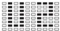
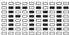
Programme 9 (F.C.M.) Programme 10 (60% H.R.C.)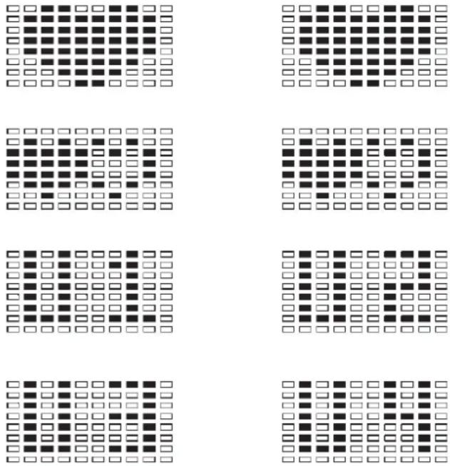
text_image
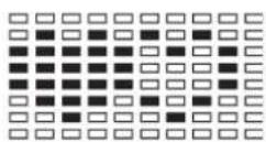
Grid of six identical square patterns, each containing a row of black and white squares with varying fill styles.E. Types corporels :
text_image
CLASS STOCK PROGRAM 18 LEVEL 18 TEST E START STOP F Christ's Sport®line
| X-axis | Maximalpuls (220-Alter) Maximum pulse rate (220-age) | 90% des Maximalpulses 90% of the maximum pulse rate | 85% des Maximalpulses 85% of the maximum pulse rate | 70% des Maximalpulses 70% of the maximum pulse rate | |---|---|---|---|---| | 20 | 200 | 180 | 170 | 140 | | 30 | 195 | 175 | 165 | 136 | | 35 | 190 | 171 | 161 | 133 | | 40 | 185 | 166 | 157 | 129 | | 45 | 180 | 162 | 153 | 126 | | 50 | 175 | 157 | 148 | 122 | | 55 | 170 | 153 | 144 | 119 | | 60 | 165 | 148 | 140 | 115 | | 65 | 160 | 144 | 136 | 112 | | 70 | 155 | 139 | 131 | 108 | | 70 | 155 | 135 | 127 | - | The chart displays a single line representing the trend of maximal pulses as a function of pulse rate. The legend indicates four distinct thresholds: Maximalpuls (220-Alter), 90% des Maximalpulses (90% of the maximum pulse rate), 85% des Maximalpulses (85% of the maximum pulse rate), and 70% des Maximalpulses (70% of the maximum pulse rate). The data points are explicitly labeled on the chart.Formules de calcul: Pouls maximum = 220 - âge
text_image
Technical diagram of a mechanical device with numbered components and alignment linesStap 3:
text_image
Technical diagram of a mechanical assembly with numbered components for identificationStap 4:
text_image
Technical diagram of a mechanical device with numbered components and labeled partsStap 5:
text_image
Technical diagram of a mechanical assembly with numbered components, likely for assembly or maintenance instructions.Stap 6:
text_image
Technical diagram showing mechanical assembly with numbered components and labeled partsStap 7:
text_image
Technical diagram of a mechanical assembly with numbered components labeled 1, 12, 13, and 14.Stap 8:
text_image
Technical diagram of a mechanical linkage system with numbered components and dashed lines indicating connectionsStap 9:
text_image
Technical diagram of a mechanical component with numbered parts and annotation arrowsStap 10:
text_image
Technical diagram of a stationary bike with numbered components for identificationStap 11:
text_image
Technical diagram of a mechanical device with numbered components, likely an electrical or mechanical assembly.Type 9 Ve taandee I 45%-49%
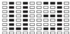
Programa 4 (Fitness)

Programma 5 (Helling) Programma 6 (Berg)


Programma 7 (Interval) Programma 8 (Lichaamsvet)
Programma 9 (Doelpols) Programma 10 (60% max. pols)
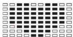
Programma 11 (75% max. pols) Programma 12 (85% max. pols)
natural_image
Repeating pattern of black rectangular blocks on white background (no text or symbols)Programma's 2 -7: Fitness
Programma's 10 - 12:
3. Planning van de training
text_image
Technical diagram of a mechanical device with numbered components and alignment linesWar 3:
text_image
Technical diagram of a mechanical assembly with numbered components for identificationWar 4:
text_image
Technical diagram of a mechanical device with numbered components and labeled partsWar 5:
text_image
Technical diagram of a mechanical assembly with numbered components, likely for assembly or maintenance instructions.War 6:
text_image
Technical diagram showing mechanical assembly with numbered components and labeled partsWar 7:
text_image
Technical diagram of a mechanical assembly with numbered components labeled 1, 12, 13, and 14.War 8:
text_image
Technical diagram of a mechanical linkage system with numbered components and dashed lines indicating connectionsWar 9:
text_image
Technical diagram of a mechanical component with numbered parts and labeled partsWar 10:
text_image
Technical diagram of a mobility device with numbered components for identificationWar 11:
text_image
Technical diagram of a mechanical device with numbered components, likely an electrical or mechanical assembly.text_image
SICCO SICCO PROGRAM 18 LEVEL 18 TEST E TEST 18 18 18 18 18 START STOP F Christ'sport Sport®text_image
top Sports© by Top-Sports Gilles GmbH D-42551 Velbert (Germany)
Service:
Tel.: +49 (0)2051/6067-0
Fax: +49 (0)2051/6067-44