SPIW309A2WF - Air-conditioner WHIRLPOOL - Free user manual and instructions
Find the device manual for free SPIW309A2WF WHIRLPOOL in PDF.
| Product type | Split air conditioner (indoor + outdoor unit) |
| Brand | Whirlpool |
| Model | SPIW309A2WF |
| Cooling mode | Cooling, heating (heat pump), ventilation, dehumidification |
| Refrigerant | R32 (GWP 675), max charge 2.5 kg |
| Power supply | Rated voltage, dedicated circuit, 16A circuit breaker (for 9K/12K models) |
| Indoor unit dimensions | Not specified in manual (typical: approx. 800-900 x 300 x 200 mm) |
| Outdoor unit dimensions | Not specified in manual (typical: approx. 700-800 x 500 x 300 mm) |
| Weight | Not specified |
| Energy class | Not specified |
| Air filter | Washable filter, clean every 200 hours (filter indicator after 720 h) |
| Main functions | 6th Sense, Sleep (4 levels), Jet (rapid cooling/heating), Around U, Super Silent, On/Off timer |
| Remote control | Infrared remote with backlit display (range 7 m, AAA batteries) |
| Wi-Fi connectivity | Integrated (Wi-Fi indicator), compatible with Wpro SmartClim (optional accessory) |
| Control panel on unit | Emergency ON/OFF button (6th Sense mode) |
| Automatic restart | Yes, adjustable (hold ON/OFF button 5 s) |
| Automatic defrost | Yes (heating mode, duration 6-10 min) |
| Operating conditions | Cooling: outdoor < 43°C, indoor > 21°C; Heating: outdoor -7°C to 24°C |
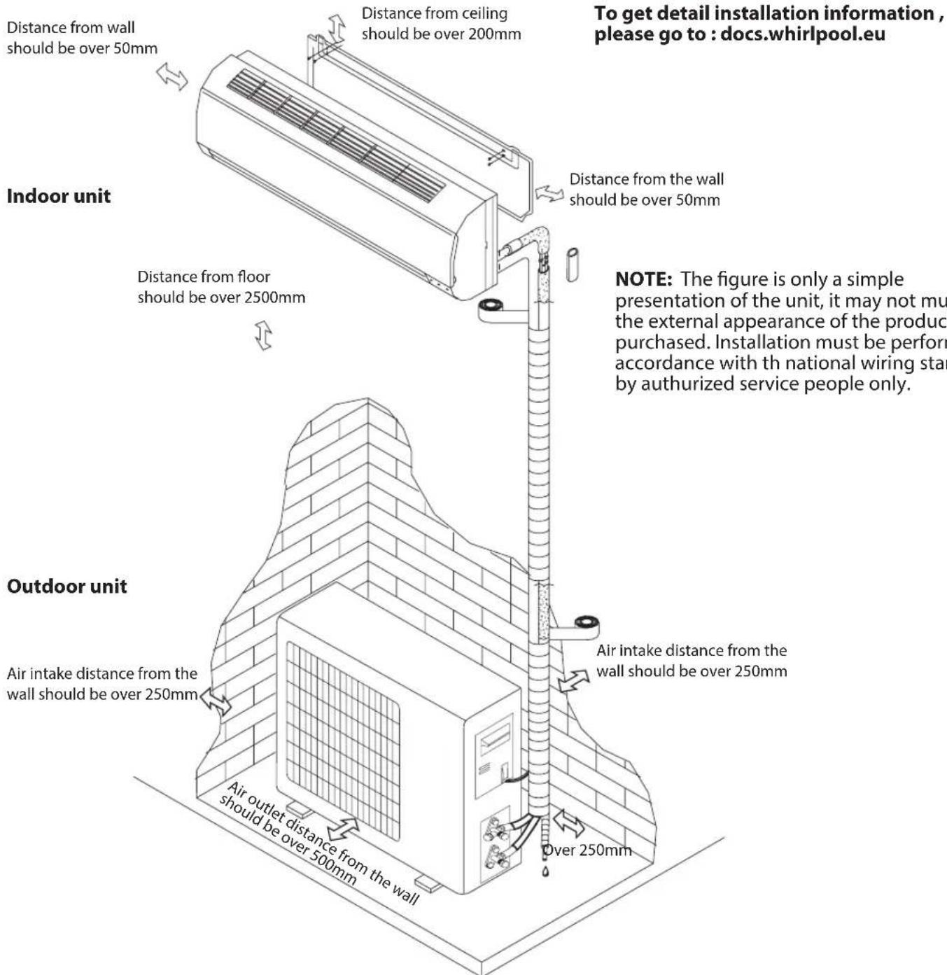
| Installation | Ceiling clearance > 200 mm, wall > 50 mm, floor > 2500 mm (indoor unit); outdoor: intake > 250 mm, outlet > 500 mm |
| Safety | Flammable refrigerant R32, automatic stop on overheating/frost, child protection (keep children 0-8 away) |
| Maintenance and cleaning | Disconnect before cleaning; front panel washable with warm water; filter washable with soapy water |
| Spare parts and repairability | Original parts recommended, repair by qualified technician (R32 refrigerant) |
| Included accessories | Remote control, batteries, user manual, installation kit (conduits, cables) |
| General information | Manual downloadable at docs.whirlpool.eu; after-sales service via label on unit |
Frequently Asked Questions - SPIW309A2WF WHIRLPOOL
User questions about SPIW309A2WF WHIRLPOOL
0 question about this device. Answer the ones you know or ask your own.
Ask a new question about this device
Download the instructions for your Air-conditioner in PDF format for free! Find your manual SPIW309A2WF - WHIRLPOOL and take your electronic device back in hand. On this page are published all the documents necessary for the use of your device. SPIW309A2WF by WHIRLPOOL.
USER MANUAL SPIW309A2WF WHIRLPOOL
Instructions for use
Gebrauchsanweisung
ENGLISH Instructions for use Page 4
- Download the complete instruction manual on docs.whirlpool.eu or call the phone number shown on the warranty booklet.
- Before using the appliance, read these safety instructions. Keep them nearby for future reference.
• These instructions and the appliance itself provide important safety warnings, to be observed at all times. The manufacturer declines any liability for failure to observe these safety instructions, for inappropriate use of the appliance or incorrect setting of controls. - Very young children (0-3 years) should be kept away from the appliance. Young children (3-8 years) should be kept away from the appliance unless continuously supervised. Children from 8 years old and above and persons with reduced physical, sensory or mental capabilities or lack of experience and knowledge can use this appliance only if they are supervised or have been given instructions on safe use and understand the hazards involved. Children must not play with the appliance. Cleaning and user maintenance must not be carried out by children without supervision.
PERMITTED USE
- CAUTION: the appliance is not intended to be operated by means of an external switching device, such as a timer, or separate remote controlled system.
- This appliance is intended to be used in household and similar applications such as: hotels and working offices.
• ⚠️ This appliance is not for professional use. - Always turn off the air conditioner by remote control first. Do not use the power supply circuit breaker or pull off the plug to turn it off. Disconnect the air conditioner from the power supply if it is to be left unused for a long period of time or during a thunder/lightning storm.
- ⚠️ Never insert obstacle in the air outlet-risk of injury. Keep ventilation openings clear of any obstruction.
- Do not place any other electrical products or household belongings under indoor unit or outdoor unit. Condensation dripping from the unit might get them wet, and may cause damage or malfunction of your property.
INSTALLATION
- The appliance must be handled and installed by two or more persons - risk of injury. Use protective gloves to unpack and install - risk of cuts.
- ⚠ Installation, including electrical connections, and repairs must be carried out by a qualified technician according to national wiring rules. Do not repair or replace any part of the appliance unless specifically stated in the user manual. Keep children away from the installation site. After unpacking the appliance, make sure that it has not been damaged during transport. In the event of problems, contact the dealer or your nearest After-sales Service. Once installed, packaging waste (plastic, styrofoam parts etc.) must be stored out of reach of children - risk of suffocation. The appliance must be disconnected from all remote power supply before any installation operation - risk of electric shock. During installation, make sure the appliance does not damage the power cable - risk of fire or electric shock. Only activate the appliance when the installation has been completed.
SAFETY INSTRUCTIONS
- ⚠ When moving or relocating the air conditioner, consult experienced service technicians for disconnection and reinstallation of the unit.
- ⚠ The appliance shall not be installed in the laundry.
ELECTRICAL WARNINGS
- The power supply must be of rated voltage with special circuitry for the appliance. The diameter of the power cord must comply with requirements.
- A multi-pole switch shall be installed in the fixed wiring in accordance with the wiring rules and the appliance must be earthed in conformity with national electrical safety standards.
- An all-pole disconnection switch having a contact separation of at least 3 mm in all poles should be connected in fixed wiring.
- Do not use extension leads, multiple sockets or adapters. The electrical components must not be accessible to the user after installation. Do not use the appliance when you are wet or barefoot. Do not operate this appliance if it has a damaged power cable or plug, if it is not working properly, or if it has been damaged or dropped.
- If the supply cord is damaged, it must be replaced with an identical one by the manufacturer, its service agent or similarly qualified persons in order to avoid a hazard - risk of electrical shock.
- A residual current device (RCD) having rated residual operation current not exceeding 30 mA shall be incorporated in fixed wiring according to national law.
- The temperature of refrigerant circuit will be high, please keep the interconnection cable away from the copper tube.
- Ensure safe grounding and a grounding wire connected with the special grounding system of the building, installed by professionals. The appliance must be fitted with electrical leakage protection switch and an auxiliary circuit breaker with sufficient capacity. The circuit breaker must also have a magnetic and a thermal tripping function to ensure protection in case of short-circuit and overload.
| Model 9K & 12K 18K 24K | |||
| Required capacity of circuit breaker 16A | 20A 25A |
- For the connection of power cord and cable connection between indoor and outdoor units, please see the wiring diagram on the appliance.
CLEANING AND MAINTENANCE
- ⚠ WARNING: Ensure that the appliance is switched off and disconnected from the power supply before performing any maintenance operation; never use steam cleaning equipment - risk of electric shock.
- Maintenance and repair requiring the assistance of other skilled personnel shall be carried out under the supervision of the person competent in the use of flammable refrigerants.
- ▲ Servicing shall only be performed with equipment as recommended by the manufacturer.
DISPOSAL OF PACKAGING MATERIALS
The packaging material is 100% recyclable and is marked with the recycle symbol ( ) The various parts of the packaging must therefore be disposed of responsibly and in full compliance with local authority regulations governing waste disposal.
SAFETY INSTRUCTIONS
DISPOSAL OF HOUSEHOLD APPLIANCES
This appliance is manufactured with recyclable or reusable materials. Dispose of it in accordance with local waste disposal regulations. For further information on the treatment, recovery and recycling of household electrical appliances, contact your local authority, the collection service for household waste or the store where you purchased the appliance. This appliance is marked in compliance with European Directive 2012/19/EU, Waste Electrical and Electronic Equipment (WEEE). By ensuring this product is disposed of correctly, you will help prevent negative consequences for the environment and human health.
The ( ) symbol on the product or on the accompanying documentation indicates that it should not be treated as domestic waste but must be taken to an appropriate collection center for the recycling of electrical and electronic equipment.
DECLARATIONS OF CONFORMITY
- The complete text of the declaration of conformity is present at the following website: docs.whirlpool.eu.
- The radio equipment operates in the 2.4 GHz ISM frequency band, the maximum radio-frequency power transmitted does not exceed 20 dBm (e.i.r.p.).
- This product includes certain open source software developed by third parties. The open source license usage statement is available at the following website: docs.whirlpool.eu.
- This product contains Fluorinated Greenhouse Gases covered by the Kyoto Protocol, the refrigerant gas being in a hermetically sealed system (R32, GWP 675). The maximum refrigerant charge amount is 2.5 kg. Please refer to the rating label for detailed information.
SAFETY INSTRUCTIONS FOR SERVICING APPLIANCE WITH SPESIFIC REFRIGERANT
- Download the complete manual for detailed installation, servicing, maintenance and repairing methods on docs.whirlpool.eu.
- Do not use means to accelerate the defrosting process or to clean, other than those recommended by the manufacturer.
- The appliance shall be stored in a well-ventilated area where the room size corresponds to the room area as specified for operation; without continuously operating ignition sources (such as; open flames, an operating gas appliance or an operating electric heater).
- Do not pierce or burn. Be aware that the refrigerants may not contain an odor.
- Any person who is involved with working on or breaking into a refrigerant circuit should hold a current valid certificate from an industry-accredited assessment authority, which authorizes their competence to handle refrigerants safely in accordance with an industry recognized assessment specification. Servicing shall only be performed as recommended by the equipment manufacturer. Maintenance and repair requiring the assistance of other skilled personnel shall be carried out under the supervision of the person competent in the use of flammable refrigerants. Appliance shall be installed, operated and stored in a room with a floor area larger than 10 m2. The installation of pipe-work shall be kept to a room with a floor area larger than 10 m2. The pipe-work shall be compliance with national gas regulations. The maximum refrigerant charge amount is 2.5 kg. Mechanical connectors used indoors shall comply with ISO 14903. When mechanical connectors are reused indoors, sealing parts shall be renewed. When flared joints are reused indoors, the flare part shall be re fabricated. The installation of pipe-work shall be kept to a minimum. Mechanical connections shall be accessible for maintenance purposes.
- Transport of equipment containing flammable refrigerants shall be compliant with the
SAFETY INSTRUCTIONS
transport regulations.
- Marking of equipment using signs shall be compliant with local regulations.
- Disposal of equipment using flammable refrigerants shall be compliant with national regulations.
- The storage of equipment / appliances should be in accordance with the manufacturer's instructions.
-
Storage of packed (unsold) equipment Storage package protection should be constructed such that mechanical damage to the equipment inside the package will not cause a leak of the refrigerant charge. The maximum number of pieces of equipment permitted to be stored together will be by local regulations.
-
Information on servicing.
6-1 Checks to the area
Prior to beginning work on system containing flammable refrigerants, safety checks are necessary to ensure that the risk of ignition is minimized. For repair to the refrigerating system the following precautions shall be complied with prior to conducting work on the system.
6-2 Work procedure
Work shall be undertaken under a controlled procedure so as to minimize the risk of flammable gas or vapour being present while the work is being performed.
6-3 General work area
All maintenance staff and others working in the local area shall be instructed on the nature of work being carried out. Work in confined spaces shall be avoided. The area around the workspace shall be sectioned off. Ensure that the conditions within the area have been made safe by control of flammable material.
6-4 Checking for presence of refrigerant
The area shall be checked with an appropriate refrigerant detector prior to and during work, to ensure the technician is aware of prentially flammable atmospheres. Ensure that hte leak detection equipment being used is suitable for use with flammable refrigerants, i.e. non-sparking adequately sealed or intrinsically safe.
6-5 Presence of fire extinguisher
If any hot work is to be conducted on the refrigeration equipment or any associated parts appropriate fire extinguishing equipment shall be available to hand. Have a dry powder or CO_2 fire extinguisher adjacent to the charging area.
6-6 No ignition sources
No person carrying out work in relation to a refrigeration system which involves exposing any pipe work that contains or has contained flammable refrigerant shall use any sources of ignition in such a manner that it may lead to the risk of fire or explosion. All possible ignition sources, including cigarette smoking, should be kept sufficiently far away from the site of installation, repairing, removing and disposal, during which flammable refrigerant can possibly be released to the surrounding space. Prior to work taking place, the area around the equipment is to be surveyed to make sure that there are no flammable hazards or ignition risks. "No Smoking" signs shall be displayed.
6-7 Ventilated area
Ensure that the area is in the open or that it is adequately ventilated before breaking into the system or conducting any hot work. A degree of ventilation shall continue during the period that the work is carried out. The ventilation should safely disperse any
SAFETY INSTRUCTIONS
released refrigerant and preferably expel it externally into the atmosphere.
6-8 Checks to the refrigeration equipment
Where electrical components are being changed, they shall be fit for the purpose and to the correct specification. At all times the manufacturer's maintenance and service guidelines shall be followed. If in doubt consult the manufacturer's technical department for assistance. The following checks shall be applied to installations using flammable refrigerants:
- The charge size is in accordance with the room size within which the refrigerant containing parts are installed;
- The ventilation machinery and outlets are operating adequately and are not obstructed;
- If an indirect refrigerating circuit is being used, the secondary circuit shall be checked for the presence of refrigerant;
- Marking to the equipment continues to be visible and legible. Markings and signs that are illegible shall be corrected;
- Refrigeration pipe or components are installed in a position where they are unlikely to be exposed to any substance which may corrode refrigerant containing components, unless the components are constructed of materials which are inherently resistant to being corroded or are suitably protected against being so corroded.
6-9 Checks to electrical devices
Repair and maintenance to electrical components shall include initial safety checks and component inspection procedures. If a fault exists that could compromise safety, then no electrical supply shall be connected to the circuit until it is satisfactory dealt with. if the fault cannot be corrected immediately but it is necessary to continue operation, an adequate temporary solution shall be used. This shall be reported to the owner of the equipment so all parts are advised. Initial safety checks shall include:
- That capacitors are discharged: this shall be done in a safe manner to avoid possibility of sparking;
- That there no live electrical components and wiring are exposed while charging, recovering or purging the system;
- That there is continuity of earth bonding.
7. Repairs to sealed components
During repairs to sealed components, all electrical supplies shall be disconnected from the equipment being worked upon prior to any removal of sealed electrical supply to equipment during servicing, then a permanently operating form of leak detection shall be located at the most critical point to warn of a potentially hazardous situation. Particular attention shall be paid to the following to ensure that by working on coelectrical components. The casing is not altered in such a way that the level of protection is affected. This shall include damage to cables, excessive number of connections, terminals not made to original specification, damage to seals, incorrect fitting of glands, etc. Ensure that apparatus is mounted securely. Ensure that seals or sealing materials have not degraded such that they no longer serve the purpose of preventing the ingress of flammable atmospheres. Replacement parts shall be in accordance with the manufacturer's specifications.
NOTE:
SAFETY INSTRUCTIONS
The use of silicon sealant may inhibit the effectiveness of some types of leak detection equipment. Intrinsically safe components do not have to be isolated prior to working on them.
- Repair to intrinsically safe components
Do not apply any permanent inductive or capacitance loads to the circuit without ensuring that this will not exceed the permissible voltage and current permitted for the equipment in use. Intrinsically safe components are the only types that can be worked on while live in the presence of a flammable atmosphere. The test apparatus shall be at the correct rating. Replace components only with parts specified by the manufacturer. Other parts may result in the ignition of refrigerant atmosphere from a leak.
- Cabling
Check that cabling will not be subject to wear, corrosion, excessive pressure, vibration, sharp edges or any other adverse environmental effects. The check shall also take into account the effects of aging or continual vibration from sources such as compressors or fans.
- Detection of flammable refrigerants
Under no circumstances shall potential sources of ignition be used in the searching for or detection of refrigerant leaks. A halide torch (or any other detector using a naked flame) shall not be used.
11.Leak detection methods
The following leak detection methods are deemed acceptable for systems containing flammable refrigerants:
- Electronic leak detectors shall be used to detect flammable refrigerants, but the sensitivity may not be adequate, or may need re-calibration (Detection equipment shall be calibrated in a refrigerant-free area.)
- Ensure that the detector is not a potential source of ignition and is suitable for the refrigerant used.
- Leak detection equipment shall be set at a percentage of the LFL of the refrigerant and shall be calibrated to the refrigerant employed and the appropriate percentage of gas (25% maximum) is confirmed.
- Leak detection fluids are suitable for use with most refrigerants but the use of detergents containing chlorine shall be avoided as the chlorine may react with the refrigerant and corrode the copper pipe-work.
- If a leak is suspected, all naked flames shall be removed/ extinguished.
- If a leakage of refrigerant is found which requires brazing, all of the refrigerant shall be recovered from the system, or isolated (by means of shut off valves) in a part of the system remote from the leak.
- Oxygen free nitrogen (OFN) shall then be purged through the system both before and during the brazing process.
- Removal and evacuation
- When breaking into the refrigerant circuit to make repairs - or for any other purpose conventional procedures shall be used. However, it is important that best practice is followed since flammability is a consideration.
The following procedure shall be adhered to:
- Remove refrigerant;
- Purge the circuit with inert gas;
- Evacuate;
SAFETY INSTRUCTIONS
- Purge again with inert gas;
- Open the circuit by cutting or brazing.
The refrigerant charge shall be recovered into the correct recovery cylinders. The system shall be “flushed” with OFN to render the unit safe. This process may need to be repeated several times. Compressed air or oxygen shall not be used for this task. Flushing shall be achieved by breaking to fill until the working pressure is achieved, then venting to atmosphere, and finally pulling down to a vacuum. This process shall be repeated until no refrigerant is within the system. When the final charge is used, the system shall be vented down to atmospheric pressure to enable work. This operation is absolutely vital if brazing operations, on the pipe-work are to take place. Ensure that the outlet for the vacuum pump is not close to any ignition sources and there is the vacuum in the system with OFN and continuing ventilation available.
13. Charging procedures
In addition to conventional charging procedures, the following requirements shall be followed:
- Ensure that contamination of different refrigerants does not occur when using charging equipment.
- Hoses or lines shall be as short as possible to minimize the amount of refrigerant contained in them.
- Cylinders shall be kept upright.
- Ensure that the refrigeration system is earthed prior to charging the system with refrigerant.
- Label the system when charging is complete (if not already).
- Extreme care shall be taken not to overfill the refrigeration system. Prior to recharging the system it shall be pressure tested with OFN.
The system shall be leak tested on completion of charging but prior to commissioning.
A follow up leak test shall be carried out prior to leaving the site.
14.Decommissioning
Before carrying out this procedure, it is essential that the technician is completely familiar with the equipment and all its detail. It is recommended good practice that all refrigerants are recovered safely. Prior to the task being carried out, an oil and refrigerant sample shall be taken in case analysis is required prior to re-use of reclaimed refrigerant. It is essential that electrical power is available before the task is commenced.
a. Become familiar with the equipment and its operation.
b. Isolate system electrically.
c. Before attempting the procedure ensure that:
- Mechanical handling equipment is available, if required, for handling refrigerant cylinders;
- All personal protective equipment is available and being used correctly;
- The recovery process is supervised at all times by a competent person;
- Recovery equipment and cylinders conform to the appropriate standards.
d. Pump down refrigerant system, if possible.
e. If a vacuum is not possible, make a manifold so that refrigerant can be removed from various parts of the system.
f. Make sure that cylinder is situated on the scales before recovery takes place.
g. Start the recovery machine and operate in accordance with manufacturer's instructions.
SAFETY INSTRUCTIONS
h. Do not overfill cylinders. (No more than 80 % volume liquid charge).
i. Do not exceed the maximum working pressure of the cylinder, even temporarily.
j. When the cylinders have been filled correctly and the process completed, make sure that the cylinders and the equipment are removed from site promptly and all isolation valves on the equipment are closed off.
k. Recovered refrigerant shall not be charged into another refrigeration system unless it has been cleaned and checked.
15. Labelling
Equipment shall be labelled stating that it has been de-commissioned and emptied of refrigerant. The label shall be dated and signed. Ensure that there are labels on the equipment stating the equipment contains flammable refrigerant.
16.Recovery
When removing refrigerant from a system, either for servicing or decommissioning, it is recommended good practice that all refrigerants are removed safely. When transferring refrigerant into cylinders, ensure that only appropriate refrigerant recovery cylinders are employed. Ensure that the correct number of cylinders for holding the total system charge is available. All cylinders to be used are designated for the recovered refrigerant and labelled for that refrigerant (i.e. special cylinders for the recovery of refrigerant). Cylinders shall be complete with pressure relief valve and associated shutoff valves in good working order. Empty recovery cylinders are evacuated and, if possible, cooled before recovery occurs. The recovery equipment shall be in good working order with a set of instructions concerning the equipment that is at hand and shall be suitable for the recovery of flammable refrigerants. In addition, a set of calibrated weighing scales shall be available and in good working order. Hoses shall be complete with leak-free disconnect couplings and in good condition. Before using the recovery machine, check that it is in satisfactory working order, has been properly maintained and that any associated electrical components are sealed to prevent ignition in the event of a refrigerant release. Consult manufacturer if in doubt. The recovered refrigerant shall be returned to the refrigerant supplier in the correct recovery cylinder, and the relevant Waste Transfer Note arranged. Do not mix refrigerants in recovery units and especially not in cylinders. If compressors or compressor oils are to be removed, ensure that they have been evacuated to an acceptable level to make certain that flammable refrigerant does not remain within the lubricant. The evacuation process shall be carried out prior to returning the compressor to the suppliers. Only electric heating to the compressor body shall be employed to accelerate this process. When oil is drained from a system, it shall be carried out safely. When moving or relocating the air conditioner, consult experienced service technicians for disconnection and reinstallation of the unit. Do not place any other electrical products or household belongings under indoor unit or outdoor unit. Condensation dripping from the unit might get them wet, and may cause damage or malfunction of your property. To keep ventilation openings clear of obstruction. The appliance shall be stored in a well-ventilated area where the room size corresponds to the room area as specified for operation. The appliance shall be stored in a room without continuously operating open flames (for example an operating gas appliance) and ignition sources (for example an operating electric heater). Reusable mechanical connectors and flared joints are not allowed.
Product description
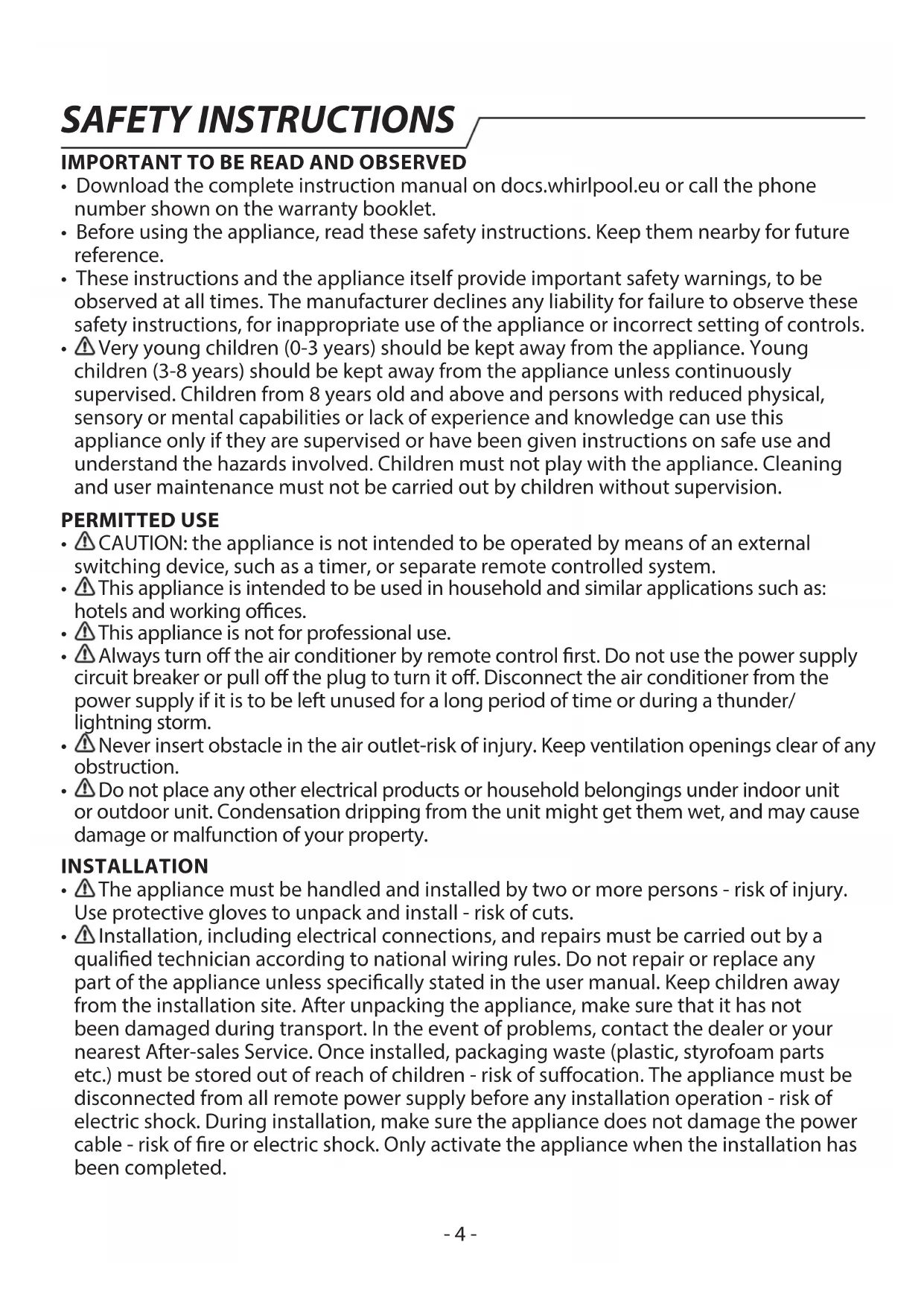
Indoor unit
The figures in this manual are based on the external view of a standard model. Consequently, the shape may differ from that of the air conditioner you have selected.
Explanation of symbols displayed on the indoor unit or outdoor unit.
 | WARNING | This symbol shows that this appliance uses a flammable refrigerant is leaked and exposer to an external ignition source, there is a risk of fire. |
 | CAUTION | This symbol shows that the operation manual should be read carefully. |
 | CAUTION | This symbol shows that a service personnel should be handling this equipment with reference to the installation manual. |
 | CAUTION | This symbol shows that information is available such as the operating manual or installation manual. |
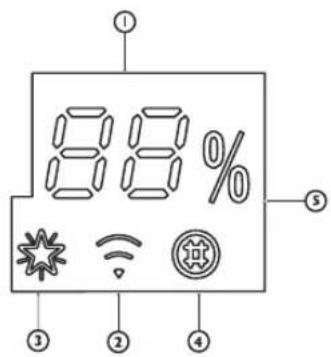

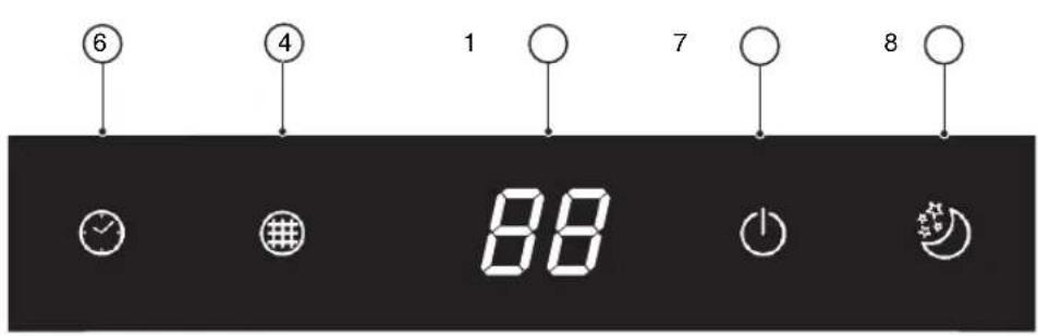
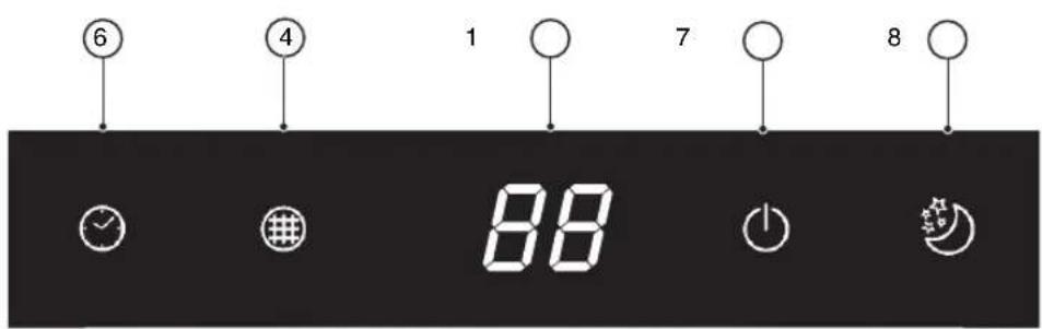
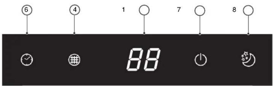
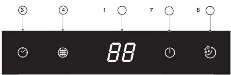
88
Temperature indicator (1)
Displays set temperature.
It shows "FC" as a reminder to clean the filter.

Wi-Fi indicator (2)
It blinks fast (3 Hz) when it's connecting to router or lose connection to router.
It blinks slowly (1.5 Hz) when it's connected to router but not connected to cloud.
It turns to be solid when the Wi-Fi is fully connected.
It goes off when the Wi-Fi is deprovisioned or turn off.

6th Sence indicator (3)
It lights up when 6th sense is on.
It goes off when 6th sense ends.

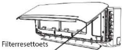
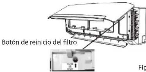
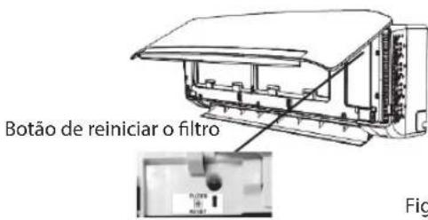
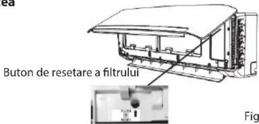
Filter monitor indicator (4)
Ilt flashes when the filter needs to be cleaned.
Filter monitor indicator flashes after 720 hours of usage as reminder to clean the filter.
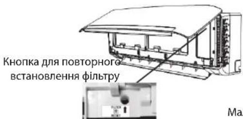
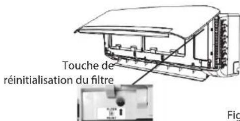
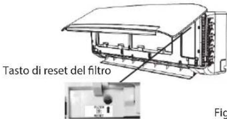
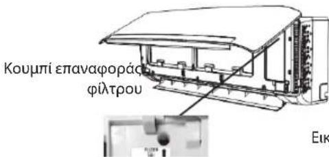
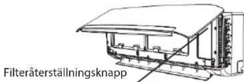
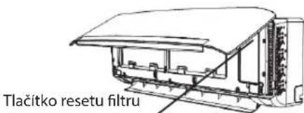
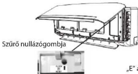
After filter cleaning, press the filter reset button located on the indoor unit behind the front panel in order to interrupt the flashing of the filter monitor indicator.

Humidity indicator (5)
It lights up when showing the humility level.
It goes off when showing the temperature.

Timer indicator (6)
It lights up during the set time.
It goes off when timer operation ends.

Running indicator (6)
It lights up during operation.
It flashes during outside unit defrosting.

Sleep indicator (8)
It lights up once sleep mode is set, "Running" indicator will flash for 10 times then the whole display will light off.
For air conditioners without Wi-Fi control, we recommend the Wpro SmartClim: a smart device to control via Wi-Fi the main settings of your appliance from your smartphone.
This accessory is not included inside the product packaging. Please contact our After-Sales Service for more details and purchase.
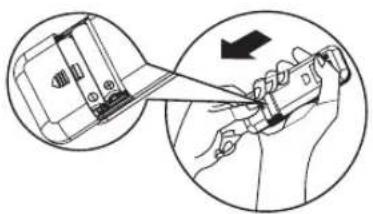
Remote controller
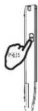
Insert the batteries into RC
- Insert a pin and gently press down on the battery cover and push in the direction of the arrow to remove, as shown.
- Insert 2 AAA batteries (1.5V) into the compartment. Ensure that "+" and "-" polarity is correctly positioned.
- Close the battery cover on the remote control.
• Remote Control presetting
• Each time the batteries are replaced in the remote controller, the remote controller pre-set at Heat Pump mode. The heat pump AC remote controller can be used to control the cool only AC models.
• Each time the batteries are replaced in the remote controller, the remote controller pre-set at Heat Pump mode. The heat pump AC remote controller can be used to control the cool only AC models.
Use RC to control the appliance
• To operate the appliance by remote control, point the remote control at the receiving device on the indoor unit, to ensure receiving sensibility.
- To send a message from remote control, the symbol will flash for 1 second. On receipt of the message, the appliance will emit a beep.
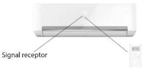
- The remote control will operate the air conditioner at a distance of up to 7m.
• Each time the batteries are replaced in the remote control, the remote control is pre-set at Heat Pump mode.
Note: please follow the instruction which matches to the remote controller you receive for Air Conditioner operation
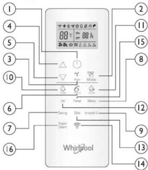
Function description of buttons (P1-03)
1. ON/OFF BUTTON
Starts or Stops the appliance by pressing this button.
3.FAN BUTTON
Used to select fan speed in sequence auto, high, medium or low.
Used to select the room temperature. Used to set the time in timer mode.
6. 6th SENSE BUTTON
Sets or cancels 6th sense operation.
7. SWING BUTTON
Stops or starts horizontal adjustment louver swinging and sets the desired up/down airflow direction.
10-11. HUMIDITY BUTTON
Used to set desired humidity level, they are only available under 6th SENSE mode.
16. SUPER SILENT BUTTON
Used to start or stop the super silent operation to have a low noise environment.
2. MODE BUTTON
Used to select the operation mode. In sequence Cooling, hearing or fan..
8.SLEEP BUTTON
Used to select the sleep mode in sequence of sleep 1, sleep 2, sleep 3 sleep 4 and sleep off.
9.AROUND U BUTTON
Used to set or cancel Around U function.
12.JET BUTTON
Used to start or stop the fast cooling or heating.
13.DIM BUTTON
Used to turn on or turn off display light on indoor unit.
14.WI-FI BUTTON
Used to trun on or turn off the Wi-Fi.
15TIMER BUTTON
Used to set the time for turn on or turn off the appliance.
Symbols on RC display Active RC by pressing UNLOCK button
* Cooling indicator Auto fan speed Sleep indicator 1 2_
Humidity plus indicator High fan speed Sleep indicator
Humidity minus indicator Medium fan speed Sleep indicator 3
Fan only indicator Low fan speed Sleep indicator 4
Heating indicator Super silent indicator 88 Display set temperature
Around U indicator 6 th SENSE indicator 88 h Display set timer
≡ Jet indicator Power save indicator Signal transmission
Press the button, the backlight will lighted up and function buttons will be activated for use. Press again to lock remote controller. If no operation on remote controller for 10s, the remote controller will be locked automatically.
Remote controller
Function description of buttons (J1-3A)
1. ON/OFF BUTTON
Starts or Stops the appliance by pressing this button.
2. MODE BUTTON
Used to select the operation mode in sequence of Cooling, dry, fan only or heating.
3. FAN BUTTON
Used to select fan speed in sequence auto, high, medium or low.
Used to select the room temperature. Used to set time in timer mode and real time clock.
6. 6 ^TH SENSE BUTTON
Sets or cancels 6^th sense operation.
7. SWING BUTTON
Stops or starts horizontal adjustment louver swinging and sets the desired up/down airflow direction.
8. SLEEP BUTTON
Sets or cancels Sleep Mode operation in sequence of
9. AROUND U BUTTON
Used to set or cancel Around U function.
10. TIMER ON/CLOCK BUTTON
Used to set the current time.
Used to set or cancel the timer on operation.
11 TIMER OFF BUTTON
Used to set or cancel the timer off operation.
12. JET BUTTON
Used to start or stop the fast cooling or heating mode.
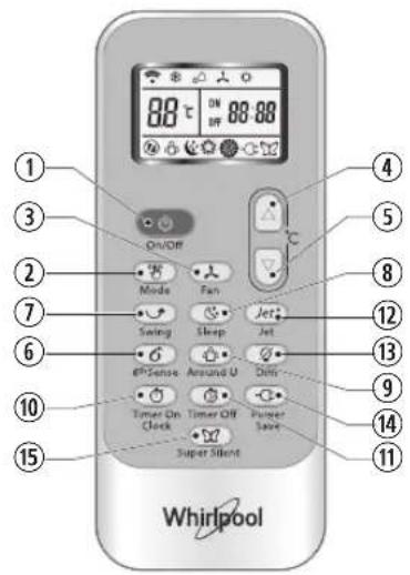
13. DIM BUTTON
Used to turn on or turn off display light on indoor unit. 14. POWER SAVE BUTTON
Used to start or stop the power save operation.
15. SUPER SILENT BUTTON
Used to start or stop the super silent operation to have a low noise environment.
Symbols on RC display
Cooling indicator Sleep 1 indicator Auto fan speed
Dry indicator Sleep 2 indicator High fan speed
Fan only indicator Sleep 3 indicator Medium fan speed*
Heating indicator Sleep 4 indicator Low fan speed
6 ^th Sense indicator Around Indicator Super silent indicator
Jet indicator
Signal transmission
88:88 Display set timer Display current time
88 = Display set temperature
Power save indicator
PROTECTION
Operating condition
The protective device maybe trip and stop the appliance in the cases listed below.
| Heating Outdoor | air temperature is over 24°C |
| Outdoor air temperature is below -7°C | |
| Room temperature is over 27°C | |
| Cooling Outdoor | air temperature is over 43°C |
| Room temperature is below 21°C | |
| Dehumidifying | Room temperature is below 18°C |
If the air conditioner runs in COOLING or DRY mode with door or window opened for a long time when relative humidity is above 80%, dew may drip down from the outlet.
Features of protection device
Wait at least 3 minutes before restarting the unit after operation stops or changing mode during operation. After connecting to power supply and turning on the appliance immediately, a delay of 20 seconds may occur before it starts to operate. If all operation has stopped, press ON/OFF button again to restart. Timer should be set again if it has been cancelled.
Features of COOLING mode Anti-freezing
When the temperature of the indoor
heat exchanger drops to 0° or below, compressor will stop working to protect the appliance.
Features of HEATING mode Preheating
In order to prevent cool air blowing, 2-5 minutes are necessary to preheat the indoor unit at HEATING operation start. The indoor fan will not work during preheating.
Defrosting
In HEATING operation the appliance will defrost (de-ice) automatically to raise efficiency. This procedure usually lasts 6-10 minutes. During defrosting, fan stops running and running indicator flashes.
After defrosting is completeed, it returns to HEATING mode automatically.
Maintenance
Clean front panel of Indoor Unit
1. Disconnect from the power supply
Turn off the appliance first before disconnecting from power supply.
2. Remove the front panel
Open the front panel as shown by the arrow (Fig. A).
Pull the slots at the side of the front panel with force to take out the front panel (Fig. B).
3. Clean the front panel
Wipe it with a soft and dry cloth. Use lukewarm water (below 40°C) to clean if the appliance is very dirty. After cleaning let it dry.
4. Refit and close the front panel
Refit and close the front panel by pushing it downward.
Note:
- Do not use substances such as gasoline or polishing powder to clean the appliance.
- Do not sprinkle water onto the indoor unit Dangerous! Electric shock!
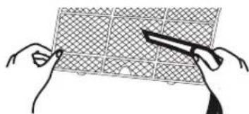
Clean Air filter
It is necessary to clean the air filter after using it for about 200 hours. Clean the air filter every two weeks if the air conditioner operates in an extremely dusty environment.
1. Disconnect from the power supply
Turn off the appliance first before disconnecting from power supply.
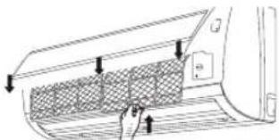
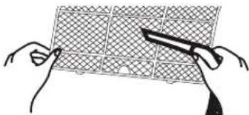
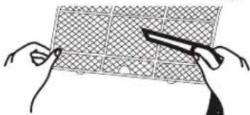
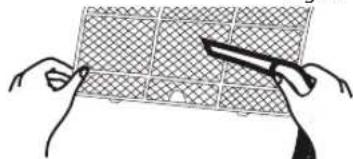
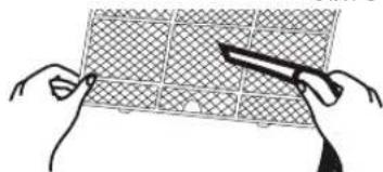
2. Take out air filter (Fig. C).
- Open the front panel. 2. Press the handle of the filter gently. 3. Slide out the filter.
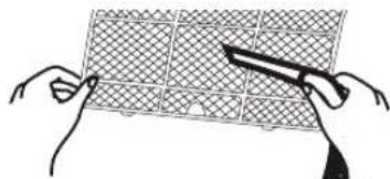
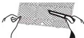
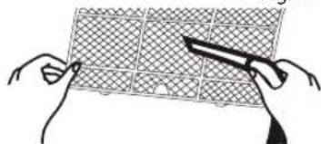
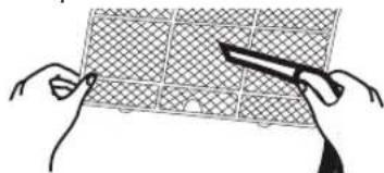
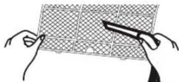
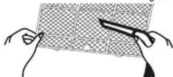
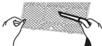
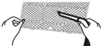
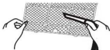
3. Cleaning the air filter (Fig. D)
If the filter is very dirty, clean it with a solution of lukewarm water and neutral detergent.
After cleaning let it dry.
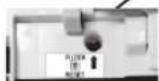
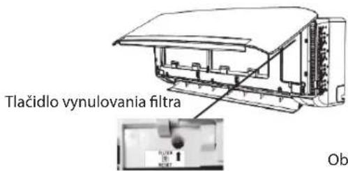
4. Refit the filter, press the filter reset button (Fig.E) at right side by using a cylinder pin and close the front panel.
Note:
- To avoid injury, do not touch the fins of indoor unit with your fingers after removing the filter.
- Do not attempt to clean the inside of the air conditioner by yourself.
- Do not clean the filter in washing machine.

Fig.A
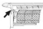
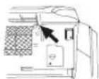
Fig.B
natural_image
Diagram of a car air conditioner interior showing airflow direction and ventilation slots (no text or labels)Fig.C
natural_image
Illustration of two hands holding a grid-patterned object with scissors, no text or symbols presentFig.D
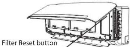
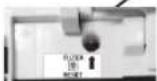
Fig.E
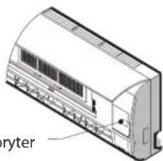
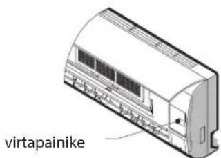
EMERGENCY OPERATION
Under emergency situation or when remote control is missing, you can control the unit by pressing the on/off switch located on the indoor unit.
- Turn on the appliance: when the unit is off, press this button, it will start up and operate in 6th SENSE mode.
- Turn off the appliance: when the unit is on, press this button, the unit will stop working.
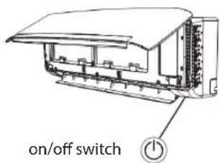
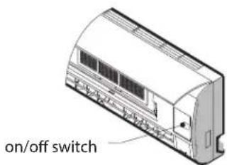
Note: Do not press this button for a long time as it will cause malfunction.
Auto-Restart Function
If you want to set auto-restart, switch on the power supply, press the ON/OFF button on the indoor unit and hold for over 5 seconds, auto-restart is set with buzz sound.
If the auto-restart has been set, press the ON/OFF button on the indoor unit and hold for over 5 seconds, auto-restart function will be cancelled with a buzz sound and air conditioner is on standby mode.
Disposal of the batteries
To protect natural resources and to promote material reuse, please separate batteries from other types of waste and recycle them through your local, free battery return system.
Installation instruction
Installation diagram
When install interconnection cord, make sure that the color of wires and the terminal No. of outdoor unit shall be same as those in indoor unit.
Cable Specifications
| Capacity (Btu/h) | Power cord Power connecting cord | |||
| Type | Normal cross - sectional area | Type | Normal cross - sectional area | |
| 7K, 9K, 12K H07 | RN-F 1.0mm | ^2X3 H07 | RN-F 1.0mm | ^2X5 |
| 18K H07RN | F 1.5mm | ^2X3 H07 | RN-F 1.5mm | ^2X5 |
| 24 K H07RN | F 2.5mm | ^2X3 H07 | RN-F 2.5mm | ^2X5 |
Operation problems are often due to minor causes, please check and refer to the following chart before contacting the service. This may save time and unnecessary expenses.
| Trouble Analysis | |
| Does not run | • Is the protection device or fuse blown?• Please wait for 3 minutes and start again, protection device may be preventing unit to work.• Are the remote control batteries low?• Is the plug not properly plugged? |
| No cooling or heating air | • Is the air filter dirty?• Are the intakes and outlets of the air conditioner blocked?• Is the temperature set properly?• Are doors or windows open? |
| Ineffective control | • Has there been a strong interference (from excessive static electricity discharge, power supply voltage abnormality)? Note that operation will be abnormal, in this case unplug from the power supply and re-plug after 2-3 seconds. |
| Does not operate immediately | • 3 minute delay will occur when changing mode during operation. |
| Peculiar smell | • This smell may come from another source such as furniture, cigarette etc, which is sucked in the unit and blown out with the air. |
| A sound of running water | • Normal behaviour caused by the flow of refrigerant in the air conditioner.• Defrosting sound in heating mode. |
| Cracking sound | • The sound may be generated by the expansion or contraction of the front panel due to temperature changes. |
| Mist sprays from the outlet | • Mist is present in the room with low temperature? Normal behaviour due to cool air discharged from indoor unit during COOLING or DRY operation mode. |
| Running indicator flashes but indoor fan stops. | • The unit is shifting from heating mode to defrost. The indicator will light off and return to heating mode. |
Note: If the problems still have, turn off the appliance and disconnect from power supply, then contact the nearest Whirlpool Authorized Service Center. Do not attempt to move, repair, disassemble, or modify the appliance by yourself.
AFTER SALES SERVICE
Before contacting the Customer Care Centre:
- Try to solve the problem yourself based on the descriptions given in the "Troubleshooting".
- Turn the appliance off and restart it to see if the fault persists.
If after carrying out the above checks, the fault persists, contact the Customer Care Centre.
Please give:
- a short description of the fault;
• the exact model of the air conditioner; - the service number (this is the number found below the word Service on service sticker which is located on the side or on the bottom of the indoor unit).
- The service number can also be found in the warranty booklet;
- your full address;
- your telephone number.
If repair work has to be carried out, contact the Customer Care Centre (Use of original spare parts and a proper repair is guaranteed). You will need to present the original invoice. Failure to comply with these instructions could compromise the safety and quality of your product.

Note: if you want the full manual for your appliance, please help to download it from website through below link: docs.whirlpool.eu using QR code.


88
natural_image
Illustration of two hands holding a grid-like object with a tool, labeled Abb. D (no text or symbols on the diagram itself)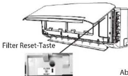
Abb. E
NOTBETRIEB
natural_image
Line drawing of a refrigerated air conditioner unit (no text or symbols)DÉCLARATIONS DE CONFORMITÉ
88
Voyant 6th Sense (3)
natural_image
Illustration of a hand holding a tool with an arrow indicating direction (no text or symbols present)natural_image
Diagram of a car air vent with airflow arrows indicating airflow direction (no text or symbols)Fig. C
natural_image
Illustration of two hands holding a grid-patterned panel with scissors, no text or symbols presentFig. D
FONCTIONNEMENT D'URGENCE
natural_image
Technical line drawing of a refrigerant air conditioner unit (no text or symbols)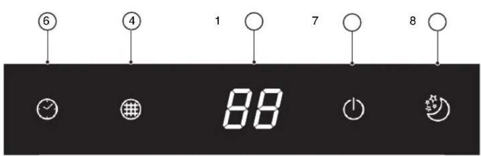
88
Indicatorlampje "Temperature" (Temperatuursindicatorlampje) (1)
• Standaardinstelling afstandsbediening
6. "6th SENSE"-TOETS (TOETS ZESDE ZINTUIG)
7. "SWING"-TOETS (ZWENKTOETS)
2. "MODE"-TOETS (MODUSTOETS)
14. "WI-FI"-TOETS (WIFITOETS)
2. "MODE"-TOETS (MODUSTOETS)
7. "SWING"-TOETS (ZWENKTOETS)
8. "SLEEP"-TOETS (SLAAPTOETS)
natural_image
Diagram of a car air conditioner interior with hand placement and arrows indicating airflow direction (no text or symbols)Afb. C
natural_image
Illustration of two hands holding a grid-patterned panel with scissors (no text or symbols)Afb. D
Afb. E
NOODBEDIENING
natural_image
Isometric line drawing of a car air conditioner unit (no text or symbols visible)
88
13. BOTÓN DIM (penumbra)
natural_image
Diagram of a car air conditioner interior showing airflow path and vent slots (no text or labels)Fig. C
natural_image
Illustration of two hands holding a grid with scissors, no text or symbols presentFig. D
natural_image
Technical line drawing of a curved air conditioner unit (no text or symbols visible)
88
Indicador da temperatura (1)
Apresenta a temperatura definida.
natural_image
Illustration of a hand holding a tool with an arrow indicating direction (no text or symbols present)3. BOTAO FAN (DE VENTOINHA)
natural_image
Diagram of a car air vent with arrows indicating airflow direction (no text or symbols)Fig. C
natural_image
Illustration of hands using scissors to cut a grid pattern (no text or symbols)Fig. D
natural_image
Illustration of a 3D air conditioner unit with cooling fins and ventilation slots (no text or symbols)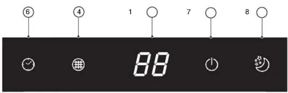
88
natural_image
Illustration of a hand holding a tool with an arrow indicating direction (no text or symbols present)2. TASTO MODE (MODALITÀ)
2. TASTO MODE (MODALITÀ)
natural_image
Diagram of a car air vent with airflow arrows indicating airflow direction (no text or symbols)Fig. C
natural_image
Illustration of two hands holding a grid with scissors, no text or symbols presentFig. D
natural_image
Technical line drawing of a car air conditioner unit (no text or symbols visible)
88
natural_image
Illustration of a hand holding a tool with an arrow indicating direction (no text or symbols present)3. KOYMΠΙ FAN (ANEMΙΣΤΗΡΑΣ)
7. KOYMΠI SWING (TALANTΩΣΗ)
8. KOYMΠI SLEEP (ΥΠΝΟΥ)
natural_image
Diagram of a car air conditioner interior showing airflow direction and ventilation grille (no text or symbols)Eik. C
natural_image
Illustration of two hands holding a grid-patterned object with scissors, no text or symbols presentEik. D
natural_image
Isometric line drawing of a car air conditioner unit (no text or symbols visible)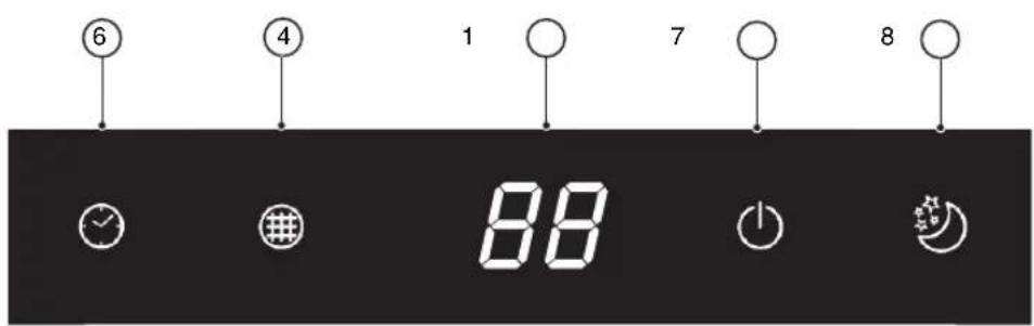
88
Temperaturindikator (1)
natural_image
Diagram of a car air conditioner interior showing airflow direction and ventilation slots (no text or labels)Bild C
natural_image
Illustration of two hands holding a grid-patterned object with a tool, no text or symbols presentBild D
natural_image
Line drawing of a refrigerated air conditioner unit (no text or symbols)RENHOLD OG VEDLIKEHOLD

88
Temperaturindikator (1)
Viser innstilt temperatur.
6th Sence indikator (3)
- Forehåndsinnstilling av fjernkontrollen
- Hver gang det skiftes batterier på fjernkontrollen, vil fjernkontrollen stilles inn på modus for Varmepumpe. Varmepumpens AC fjernkontroll kan benyttes til å kontroller nedkjøling kun på AC modeller.
natural_image
Pure diagram of a roof structure with triangular roof lines and no text or symbols8.SLEEP (HVILE) KNAPP
3. FAN (VIFTE) KNAPP
natural_image
Diagram of a car air conditioner interior showing airflow direction and component placement (no text or symbols)Fig. C
natural_image
Illustration of two hands holding a grid-patterned panel with scissors, no text or symbols presentFig. D
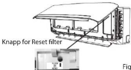
Fig. E
INNGREP I N∅DSSITUASJON
on/off bryter
natural_image
Technical line drawing of a cryter air conditioner unit (no text or symbols on the device itself)Auto-Restart (automatisk omstart) funksjon
88
Temperaturindikator (1)
Viser den indstillede temperatur.
"FC" visualiseres, for at minde om rengøring af filteret.

WiFi-indikator (2)
6th SENSE indikator (3)
6. KNAPPEN 6th SENSE
Aktiverer eller inaktiverer funktionen 6th sense.
7. KNAPPEN SWING
natural_image
Diagram of a hand inserting a mesh-lined panel into a car air vent (no text or symbols)Fig. C
natural_image
Illustration of two hands holding a grid-patterned object with a knife (no text or symbols)Fig. D
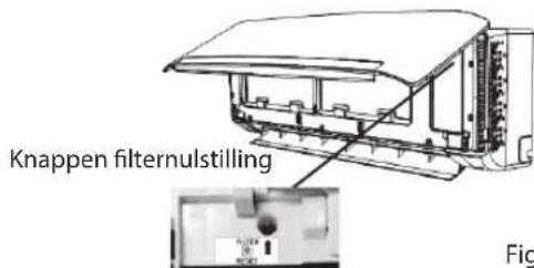
Fig. E
N∅DBETJENING
natural_image
Technical line drawing of a wall-mounted air conditioner unit (no text or symbols visible)
88
natural_image
Illustration of two hands holding a grid-like structure with a tool, labeled 'Kuva D' (no other text or symbols)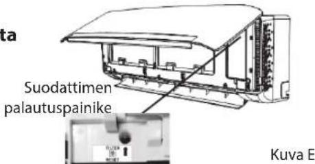

88
natural_image
Illustration of a hand holding a tool with an arrow indicating direction (no text or symbols present)1. PRZYCISK ON/OFF (WŁ./WYŁ)
6. PRZYCISK 6th SENSE
1. PRZYCISK ON/OFF (WŁ./WYŁ)
natural_image
Technical line drawing of a curved air conditioner unit with ventilation slots and control panel (no text or symbols)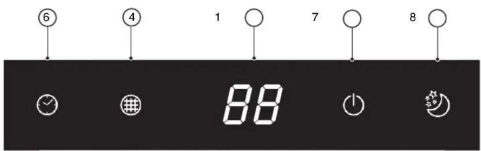
88
Indikátor teploty (1)
Zobrazuje nastavenou teplotu.
4–5. TLAČÍTKO TEMPERATURE (TEPLOTA)
natural_image
Diagram of a car air conditioner interior showing airflow direction and component placement (no text or symbols)Obr. C
natural_image
Illustration of two hands holding a grid with scissors, no text or symbols presentObr. D
Obr. E
NOUZOVÉ OVLÁDÁNÍ
natural_image
Isometric line drawing of a wall-mounted air conditioner unit (no text or symbols)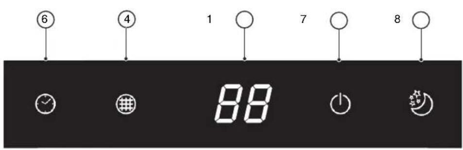
88
Indikátor teploty (1)
Zobrazuje nastavenú teplotu.
4-5. TLAČIDLO TEPLOTY
6. TLACIDLO 6th SENSE
4-5. TLAČIDLO TEPLOTY
13. TLAČIDLO DIM
natural_image
Diagram of a car air vent with airflow arrows indicating airflow direction (no text or symbols)Obr. C

natural_image
Illustration of two hands holding a grid with scissors, no text or symbols presentObr. D
88
natural_image
Illustration of a hand holding a tool with an arrow indicating direction (no text or symbols present)natural_image
Diagram of a car air conditioner interior showing airflow direction and component placement (no text or symbols)„C“ ábra
natural_image
Illustration of two hands holding a grid with scissors, no text or symbols present„D“ ábra
natural_image
Technical line drawing of a wall-mounted air conditioner unit (no text or symbols visible)
88
natural_image
Diagram showing a hand holding a tool with an arrow indicating direction (no text or symbols present)natural_image
Diagram of a car interior showing airflow or ventilation system with arrows indicating direction (no text or symbols)Рис. С
natural_image
Illustration of two hands holding a grid with scissors, no text or symbols presentРис. D
88
natural_image
Diagram showing a hand holding a device with a tool, and a magnified inset of the device's internal structure (no text or symbols)natural_image
Pure diagram of a rectangular object with diagonal lines, no text or symbols present
88
Indicator 6th Sense (3)
• Presetarea telecomenzii
6. BUTÔNUL FUNCTIEI 6th SENSE
2. BUTONUL MODE (DE MOD)
2. BUTONUL MODE (DE MOD)
6. BUTONUL FUNCTIEI 6th SENSE
natural_image
Diagram of a car interior showing airflow or ventilation system with arrows indicating direction (no text or symbols)Fig. C
natural_image
Illustration of two hands holding a grid-patterned panel with scissors (no text or symbols)Fig. D
natural_image
Technical line drawing of a refrigerant air conditioner unit (no text or symbols visible)
88
natural_image
Illustration of two hands holding a grid-patterned panel with scissors, labeled 'Man. D' (no text or symbols on the diagram itself)