
VMM501 - Electronics kit VELLEMAN - Free user manual and instructions
Find the device manual for free VMM501 VELLEMAN in PDF.

| Product type | Educational electronics kit based on micro:bit |
| Brand | Velleman |
| Model | VMM501 |
| Approximate dimensions | 200 x 150 x 50 mm (box) |
| Approximate weight | 300 g |
| Power supply | micro:bit board via USB port (5 V) or 2x AA battery holder (1.5 V each) |
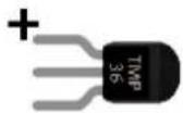
| Included components | micro:bit board, breadboard adapter, breadboard, LEDs (red, RGB), resistors (100 Ω, 10 kΩ), 10 kΩ potentiometer, photocell, switches (momentary, toggle), TMP36 temperature sensor, mini servo, buzzer, mini motor, MOSFET transistor, diode, 8-LED RGB ring, jumper wires, battery holder |
| Main functions | Learning programming and electronics through 11 hands-on projects: LED blinking, button control, potentiometer reading, brightness, RGB LED, toggle switch, temperature, servo, buzzer, motor, rainbow LED |
| Software environment | Microsoft MakeCode (block editor and JavaScript) online at makecode.com |
| Usage | Indoor only. Suitable for children aged 8 and up under adult supervision |
| Care and cleaning | Clean with a dry cloth. Do not use chemicals. Protect from moisture and splashes |
| Safety | Do not expose to rain or moisture. Use only indoors. Keep out of reach of children under 8 without supervision. Disconnect before cleaning |
| Spare parts and repairability | Standard electronic components available separately. No specific spare parts provided by Velleman |
| Warranty | 24 months for consumer products (EU). Covers manufacturing defects. Keep purchase receipt |
| Environmental information | Do not dispose of with household waste. Recycle at appropriate collection point according to local regulations |
| Manual languages | French, German, English, Spanish, Dutch, Polish, Portuguese |
Frequently Asked Questions - VMM501 VELLEMAN
User questions about VMM501 VELLEMAN
0 question about this device. Answer the ones you know or ask your own.
Ask a new question about this device
Download the instructions for your Electronics kit in PDF format for free! Find your manual VMM501 - VELLEMAN and take your electronic device back in hand. On this page are published all the documents necessary for the use of your device. VMM501 by VELLEMAN.
USER MANUAL VMM501 VELLEMAN
MOTOR SHIELD FOR MICRO:BIT
natural_image
Assorted electronic components including micro-bit, batteries, sensors, and a breadboard (no visible text or symbols)USER MANUAL 2
HANDLEIDING 27
MODE D'EMPLOI 53
MANUAL DEL USUARIO 79
To all residents of the European Union
Important environmental information about this product

This symbol on the device or the package indicates that disposal of the device after its lifecycle could harm the environment. Do not dispose of the unit (or batteries) as unsorted municipal waste; it should be taken to a specialized company for recycling. This device should be returned to your distributor or to a local recycling service. Respect the local environmental rules.

If in doubt, contact your local waste disposal authorities.
Thank you for choosing Velleman®! Please read the manual thoroughly before bringing this device into service. If the device was damaged in transit, do not install or use it and contact your dealer.
2. Safety Instructions

This device can be used by children aged from 8 years and above, and persons with reduced physical, sensory or mental capabilities or lack of experience and knowledge if they have been given supervision or instruction concerning the use of the device in a safe way and understand the hazards involved. Children shall not play with the device. Cleaning and user maintenance shall not be made by children without supervision.

Indoor use only.
Keep away from rain, moisture, splashing and dripping liquids.
3. General Guidelines

- Refer to the Velleman ^ Service and Quality Warranty on the last pages of this manual.
- Familiarise yourself with the functions of the device before actually using it.
- All modifications of the device are forbidden for safety reasons. Damage caused by user modifications to the device is not covered by the warranty.
- Only use the device for its intended purpose. Using the device in an unauthorised way will void the warranty.
- Damage caused by disregard of certain guidelines in this manual is not covered by the warranty and the dealer will not accept responsibility for any ensuing defects or problems.
- Nor Velleman nv nor its dealers can be held responsible for any damage (extraordinary, incidental or indirect) – of any nature (financial, physical...) arising from the possession, use or failure of this product.
- Due to constant product improvements, the actual product appearance might differ from the shown images.
- Product images are for illustrative purposes only.
- Do not switch the device on immediately after it has been exposed to changes in temperature. Protect the device against damage by leaving it switched off until it has reached room temperature.
- Keep this manual for future reference.
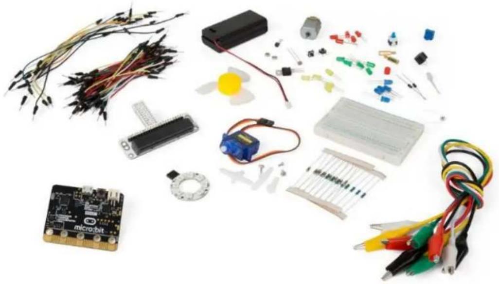
4. Description
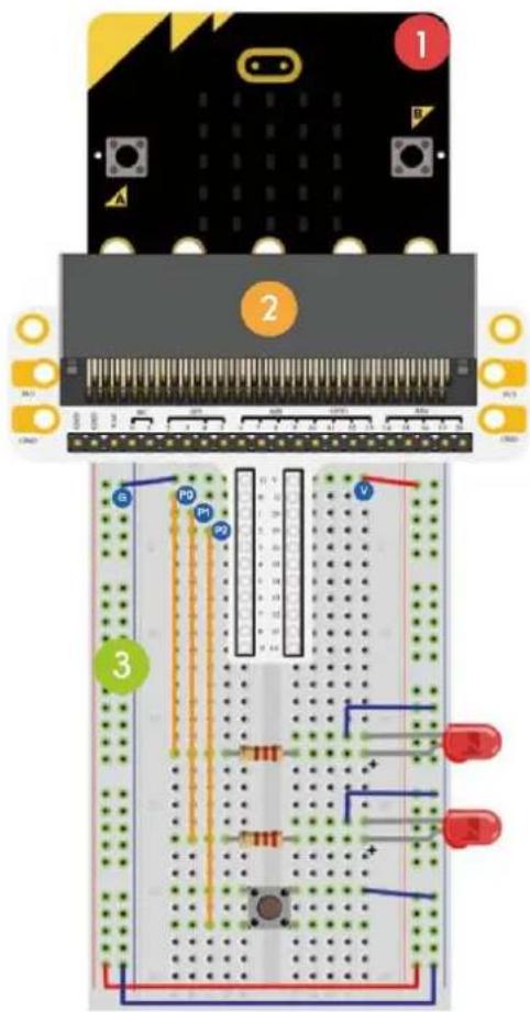
This starter kit is an educational kit based on micro:bit. It comes with basic electronic components, a breadboard, connection wires and a micro:bit.
5. Examples
5.1 LED

1x micro:bit board

1x micro:bit breadboard adapter

1x breadboard

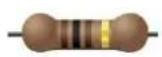
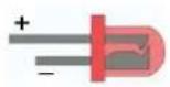
2x red LED (polarisation: anode (+) = long leg, cathode (-) = short leg)

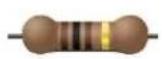
2x 100 Ω resistor (brown/black/brown/gold)
4
5
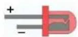
In this course, we are going to use micro:bit to make two LEDs twinkle alternatively.
Place the necessary components on the breadboard as shown.
text_image
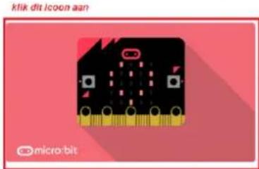
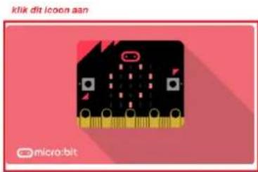
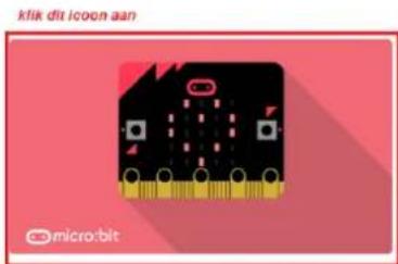
Diagram of a breadboard with labeled components and colored wires, showing circuit layout and pin connections.The programme is written in code blocks, online in the web browser. Open the website www.makecode.com or https://www.microsoft.com/en-us/makecode?rtc=1, click the micro:bit icon and click Start Project.

text_image
Microsoft Office Windows Surface Xbox Deals Support More Search Microsoft.com Sign in MakeCode About Get started Resources Hands on computing education Microsoft MakeCode brings computer science to file for all students with fun projects, immediate results, and both block and text editors for learners at different levels. klik dit icon aan micro.bit adafruit MIMEERIFT micro.bit Start coding with micro.bit > Circuit Playground Express > Start coding with Circuit Playground Express > Minecraft Start coding with Minecraft >The micro:bit code block opens in a new window. Now, we can start composing the code with code blocks, which we drag and drop from a code drawer to a code editor.
Read below how this works...
What is MakeCode?
Formerly PXT - Programming eXperience Toolkit Editor to write code for the micro:bit.
A graphical, beginner-friendly drag-and-drop code editor similar to Scratch. It works online, in the browser.
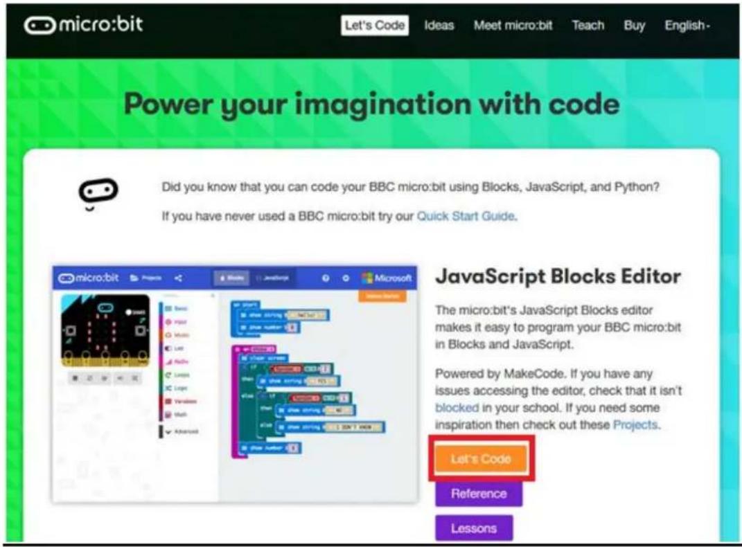
text_image
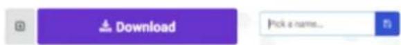
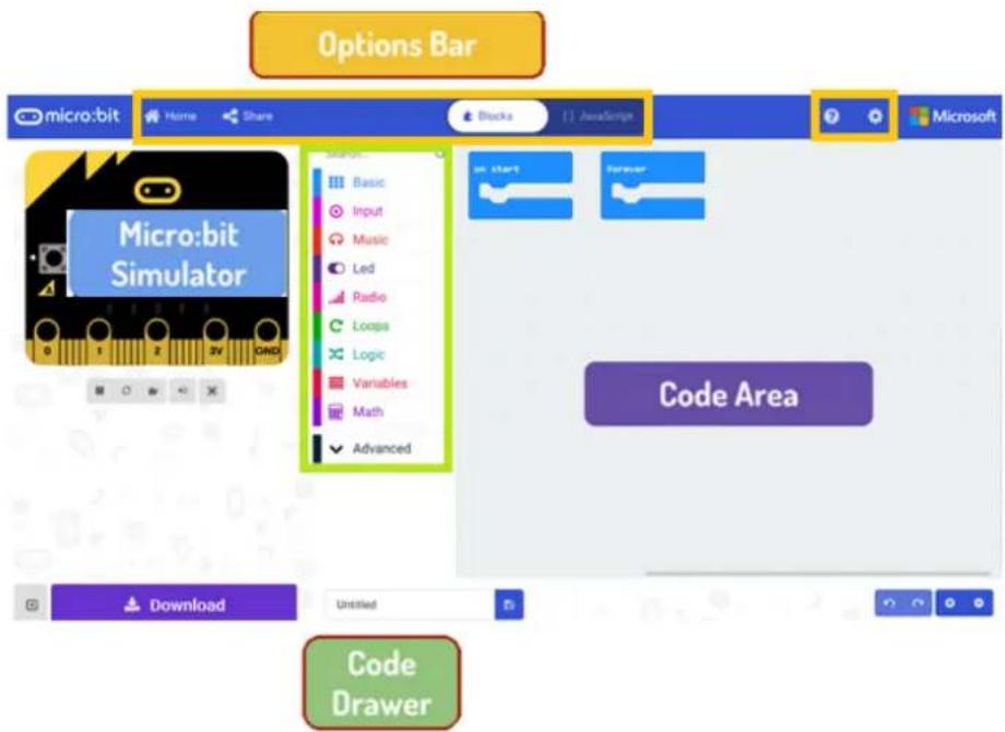
micro:bit Let's Code Ideas Meet micro:bit Teach Buy English- Power your imagination with code Did you know that you can code your BBC micro:bit using Blocks, JavaScript, and Python? If you have never used a BBC micro:bit try our Quick Start Guide. Microsoft micro:bit Projects BBO Java Microsoft BBO Java Java Java Java Java Java Java Java Java Java Java Java Java Java Java Java Java Java Java Java Java Java Java Java Java Java Java Java Java Java Java Java Java Java Java Java Java Java Java Java Java Java Java Java Java Java Java Java Java Java BBO Java BBO Java Java Java Java Java Java Java Java BBO Java BBO Java Java Java Java Java Java BBO Java BBO Java Java Java Java BBO Java BBO Java BBO Java BBO Java BBO Java BBO BBO BBO BBO BBO BBO BBO BBO BBO BBO BBO BBO BBO BBO BBO BBO BBO BBO BBO BBO BBO BBOYou can see the editor is made up of different sections. You make your code in the Code Area, dragging out blocks from the Code Drawer. You can immediately see your code results in the micro:bit simulator. At the bottom is where you download and save your project.
Next, we will take a closer look at how to use the Options Bar for doing other things.
text_image
Options Bar micro:bit Home Share Blocks JavaScript Microsoft Micro:bit Simulator Code Area Download Untitled Code DrawerOptions Bar
text_image
New Project Import Blocks JavaScript Support Getting started Projects Reference Blocks JavaScript Hardware Buy
text_image
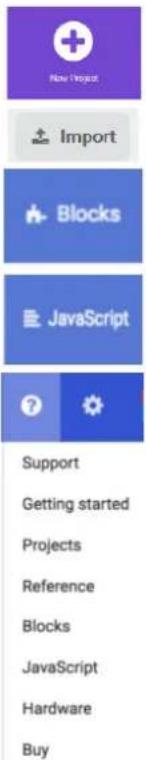
Microsoft Project Settings Extensions Delete Project Report Abuse... Language High Contrast On Reset About...Click to create or add a new project.
Import your projects here.
Open up the Blocks interface to write your scripts with the Block editor.
Open up the Javascript interface to type out your script in the Javascript language.
Handy reference when you are unsure about how the various blocks and functions work.
Shortcuts to changing project properties. Rename and delete your projects here. Reset deletes all the projects that you have saved, so be very careful. Most of the time, you will just want to stick to Delete Project.
Using the LED Bar
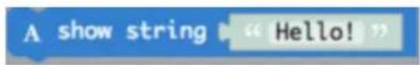
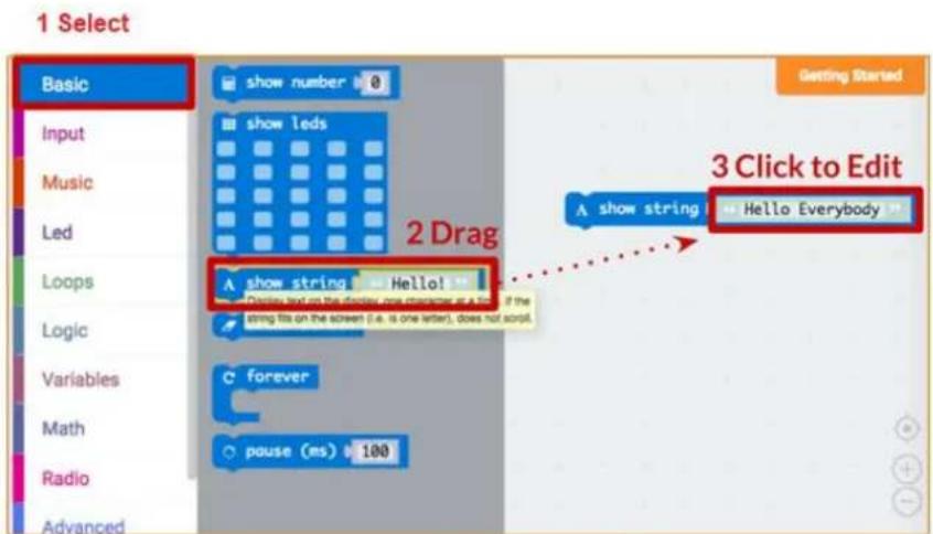
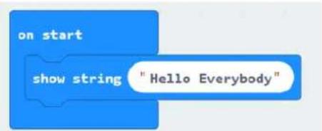
We start by writing some code! Each time you select from the Code Drawer, it will list all the codes available to you. Drag out the show string block and click inside the box to edit.
text_image
1 Select Basic show number 0 Input show leds Music Led Loops Logic Variables Math Radio Advanced Getting Started 2 Drag A show string Hello Everybody A show string Hello! Display text on the screen one completely as a time if the string fits on the screen (i.e. is one letter), does not sort. C forever pause (ms) 100 3 Click to Edit| 1 | Select |
| 2 | Drag |
3 Click to edit
text_image
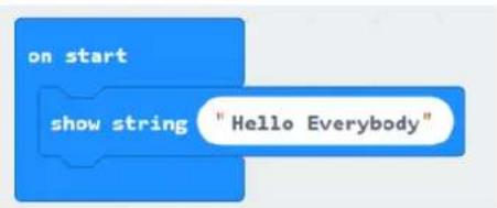
on start show string "Hello Everybody"See what happens in the micro:bit simulator!
Say Hello!
The text you have been displaying are called strings.
You can show any integer in the LED screen using show number or any 5x5 pixel image using show leds.
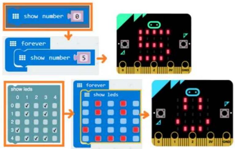
flowchart
graph TD
    A["show number"] --> B["forever"]
    B --> C["show number 5"]
    C --> D["0 1 2 3V OND"]
    D --> E["0 1 2 3V OND"]
    E --> F["0 1 2 3V OND"]
    F --> G["0 1 2 3V OND"]
    G --> H["0 1 2 3V OND"]
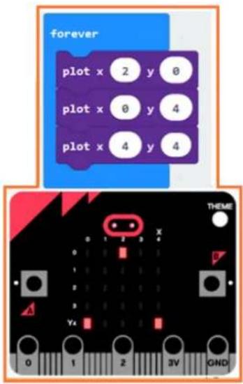
You can also plot one point LED at the time using co-ordinates. Co-ordinate (0,0) is the top left corner.
text_image
forever plot x 2 y 0 plot x 0 y 4 plot x 4 y 4 THEME 0 1 2 3 4 A Y4 0 1 2 3V GNDJoining Blocks
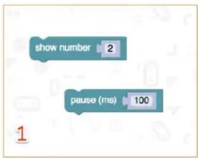
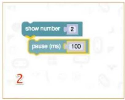
Click and hold the block you would like to join. Drag the block to the target block until a side of the target block is highlighted. Release and the two blocks are now joined!
Clicking on the first block will move the second; clicking on the second will detach it from the first.
text_image
show number 2 pause (ms) 100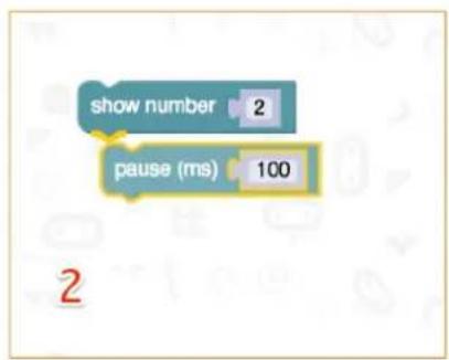
text_image
show number 2 pause (ms) 100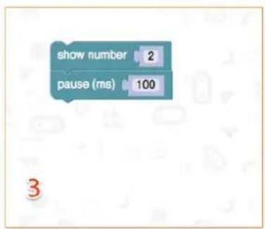
text_image
show number 2 pause (ms) 100Testing on micro:bit
Connect the micro;bit to your computer using a micro-USB cable.
It will go through a default sequence, asking you to press buttons and play a game. Try it out!
Click Download to translate your script to a hex file and to download it.
If you set Chrome up properly, you will not need this next step. Drag the downloaded hex file to the micro:bit drive, or right-click and Send To in Windows®.
You have just programmed your very own device!
Have a look at the code below.
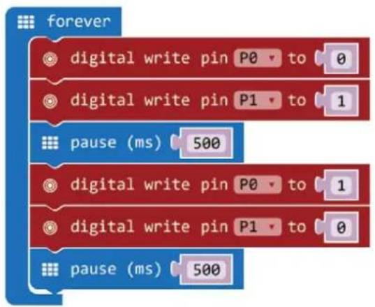
flowchart
graph TD
    A[" forever"] --> B[" digital write pin P0 to 0 "]
    A --> C[" digital write pin P1 to 1 "]
    A --> D[" pause (ms) 500 "]
    A --> E[" digital write pin P0 to 1 "]
    A --> F[" digital write pin P1 to 0 "]
    A --> G[" pause (ms) 500 "]
| 1. | Drag and drop the code blocks to form the code as shown.You can find thedigital write pin P0 to 0 block inAdvanced → Pins in the Code Drawer. You can find theforeverand pause (ms) 100 in Basic in the Code Drawer. |
| 2. | Set value for P0 to 0. LED0 off = low voltage = 0 V = digital 0. Set value for P1 to 1. LED1 on = high voltage = 5 V = digital 1. |
| 3. | Set thepauseto 500 ms. |
| 4. | Set value for P0 to 1. LED0 on = high voltage = 5 V = digital 1. Set value for P1 to 0. LED1 off = low voltage = 0 V = digital 0. |
| 5. | Set thepauseto 500 ms. |
| 6. | When complete, we compile the programme and generate a hex. file. Click on the download button and save the hex. file to the Downloads folder → C:\downloads. This hex. file is ready to upload to the micro:bit.Plug the micro:bit into a USB port. The, drag and drop the hex. file onto the micro:bit removable device to upload the programme. |
You will see the two LEDs flash alternatively. Now, why not make an RGB traffic light?
5.2 Button
1
1x micro:bit board
2
1x micro:bit breadboard adapter
3
1x breadboard
4
2x red LED (polarisation: anode (+) = long leg, cathode (-) = short leg)
5
2x 100 Ω resistor (brown/black/brown/gold)
6
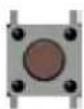
1x momentary push button
4
5
6
We use a button to control the LED flash. Press the button to make the LED flash in turns. Release to switch off the LED.
Place the necessary components on the breadboard as shown.
Have a look at the code below.
text_image
Diagram of an electronic circuit board with labeled components and wiring, including a breadboard layout and indicator lights.
flowchart
graph TD
A["on start"] --> B["set pull pin P2 to up"]
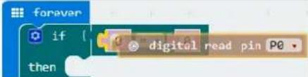
C["forever"] --> D{if digital read pin P2}
D --> E["0"]
D --> F["then digital write pin P0 to 0"]
D --> G["0"]
D --> H["0"]
D --> I["0"]
D --> J["0"]
D --> K["0"]
D --> L["pause (ms) 500"]
D --> M["digital write pin P0 to 1"]
D --> N["digital write pin P1 to 0"]
D --> O["pause (ms) 500"]
- Drag and drop the code blocks to form the code as shown.
You can find the digital read pin P0 and digital write pin P0 to 0 blocks in Advanced → Pins in the Code Drawer. You can find the forever and pause (ms) 100 in Basic in the Code Drawer. You can find the if then and logic equal function blocks in Logic in the Code Drawer.
Drag the logic equal function block and drop it over the true block.
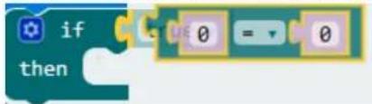
text_image
if thenThe two blocks will snap together.
Drag the digital read pin PO block and drop it over the 0 of the logic equal function block as shown.
 | |
| 2. | Set P2 to be a pull-up. |
| 3. | Set thedigital read pinto P2. |
| 4. | Set thedigital write pin P0 to 0(active low (0 V)).Set thedigital write pin P1 to 1(active high (5 V)). |
| 5. | Set thepauseto 500 ms. |
| 6. | Set thedigital write pin P0 to 1(active high (5 V)).Set thedigital write pin P1 to 0(active low (0 V)). |
| 7. | Set thepauseto 500 ms. |
| 8. | When complete, we compile the programme and generate a hex. file. Click on the download button and save the hex. file to the Downloads folder →C:\downloads. This hex. file is ready to upload to the micro:bit.Plug the micro:bit into a USB port. The, drag and drop the hex. file onto the micro:bit removable device to upload the programme. |
Press the button and you will see the LED flash alternatively. Now, how to light the red LED with the button pressed and light the green LED with the button released?
5.3 Trimpot
1
1x micro:bit board
2
1x micro:bit breadboard adapter
3
1x breadboard
4
1x 10 kΩ trimmer
4
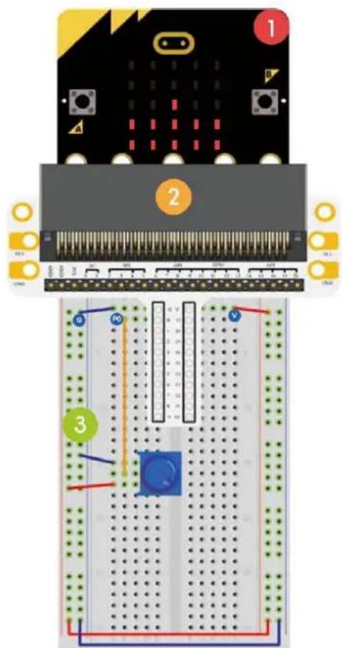
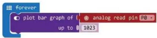
We are going to read the output voltage of the trimpot and display it on the micro:bit screen with a bar graph.
Place the necessary components on the breadboard as shown.
text_image
Diagram of an electronic circuit board with labeled components and wiring, showing connections between a breadboard and a PCB.Have a look at the code below.
text_image
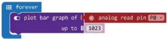
plot bar graph of up to analog read pin P0 1023| 1. | Drag and drop the code blocks to form the code as shown.You can find the plot bar graph of 0 up to 0 block in LED in the Code Drawer. |
| 2. | Set analog read pin to P0. You can find this block in Pins in the Code Drawer. Set the value up to 1023. |
| 3. | When complete, we compile the programme and generate a hex. file. Click on the download button and save the hex. file to the Downloads folder → C:\downloads. This hex. file is ready to upload to the micro:bit.Plug the micro:bit into a USB port. The, drag and drop the hex. file onto the micro:bit removable device to upload the programme. |
Rotate the trimmer. The voltage will be displayed on the micro:bit screen through a bar graph. When the voltage is 0, the LED screen displays a pixel spot only. When it is 3.3 V, the whole screen will be illuminated. Now, how would you use the trimmer to adjust the LED's brightness?
5.4 Photocell
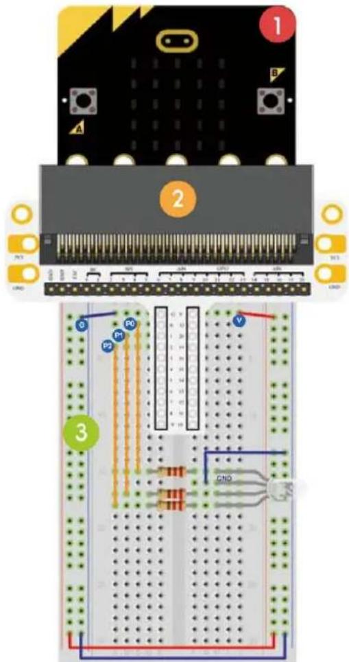
1x micro:bit board
2 1x micro:bit breadboard adapter
3 1x breadboard
4 1x photocell
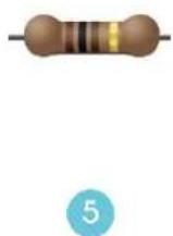
5 1x 10 kΩ resistor (brown/black/black/red/bruin)
text_image
C+ E 4 5Short leg = collector Positive anode Long leg = emitter Negative cathode
We are going to use a photocell to control the brightness of the micro:bit screen.
text_image
Diagram of an electronic breadboard layout with labeled components and wiring connectionsPlace the necessary components on the breadboard as shown.
Have a look at the code below.
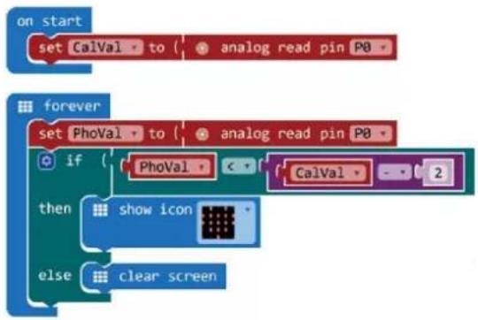
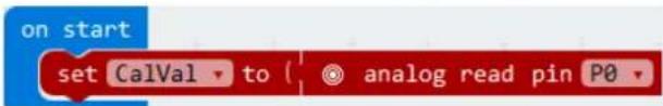
flowchart
graph TD
    A["on start"] --> B["set CalVal to analog read pin P0"]
    C["forever"] --> D["set PhoVal to analog read pin P0"]
    D --> E{if}
    E --> F["PhoVal"]
    F --> G{CalVal - 2}
    G --> H["then show icon"]
    H --> I["else clear screen"]
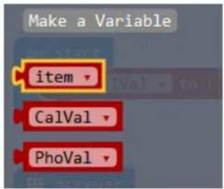
- First, we make two variables. Go to Variables in the Code Drawer and click on Make a Variable.
New variable name:
CalVal

Cancel

Enter CalVal in the window and click Ok. Enter PhoVal in the window and click Ok.
You will see two new variables under Variables in the Code Drawer.
text_image
Make a Variable item CalVal PhoValWe will need these variables later to save the data in a register.
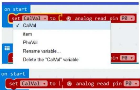
You can find the logic smaller than function and the if then else blocks in Logic in the Code Drawer. You can find the mathematical function minus block in Math in the Code Drawer. You can find the show icon block in Basic in the Code Drawer. You can find the clear screen block in Basic → More in the Code Drawer. You can find the set item to 0 block in Variables in the Code Drawer. Click on the arrow and select CalVal or PhoVal.
text_image
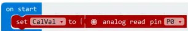
on start set CalVal to analog read pin P0 ✓ CalVal item PhoVal Rename variable... Delete the "CalVal" variable on start set CalVal to analog read pin P0- Select the CalVal variable and set the analog read pin to P0.
text_image
on start set CalVal to analog read pin P0| 3. | In the forever block, select the PhoVal variable and set the analog read pin to P0.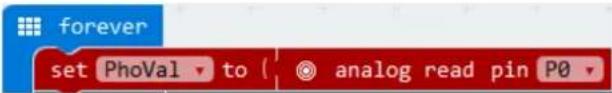 |
| 4. | Drag the logic smaller than function next to the if block and drop it over the true block.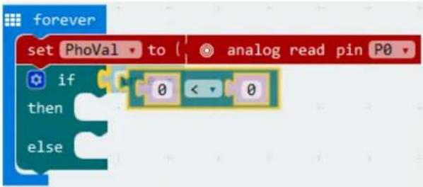 Next, we drag and drop the PhoVal variable (from Variables in the Code Drawer) and drop it over the first 0 of the logic smaller than function. Next, we drag and drop the PhoVal variable (from Variables in the Code Drawer) and drop it over the first 0 of the logic smaller than function.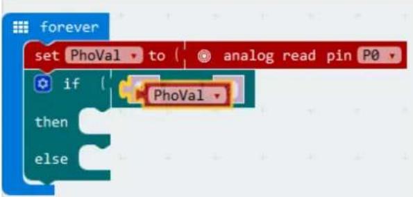 Drag the mathematical function minus block and drop it over the second 0 of the logic smaller than function. Drag the mathematical function minus block and drop it over the second 0 of the logic smaller than function.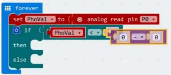 Next, we drag and drop the CalVal variable (from Variables in the Code Drawer) and drop it over the first 0 of the mathematical function minus block. Set the second 0 of the mathematical function minus block to 2. Next, we drag and drop the CalVal variable (from Variables in the Code Drawer) and drop it over the first 0 of the mathematical function minus block. Set the second 0 of the mathematical function minus block to 2.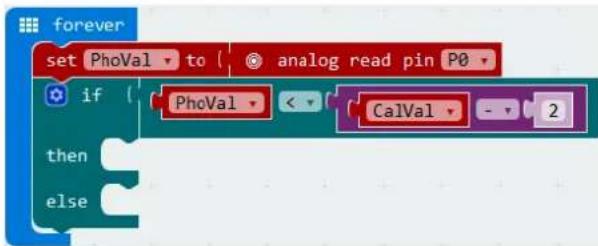 |
| 5. | Drag and drop the show icon block next to the then block. Drag and drop the clear screen block next to the else block. |
| 6. | When the PhoVal is smaller than CalVal - 2, the display will show a heart. Else, it will switch off. |
| 7. | When complete, we compile the programme and generate a hex. file. Click on the download button and save the hex. file to the Downloads folder → C:\downloads. This hex. file is ready to upload to the micro:bit.Plug the micro:bit into a USB port. The, drag and drop the hex. file onto the micro:bit removable device to upload the programme. |
Note: reset the micro:bit to calibrate the reference value according to the current brightness. To run the programme properly, we must start with the light switched on.
When the light is switched on, nothing is displayed. When the light is switched off, the heart is displayed. Now, how can we use a photocell to control an LED?
5.5 RGB LED

1x micro:bit board
1x micro:bit breadboard adapter
1x breadboard
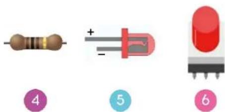
1x RGB LED (common cathode)
3x 10 Ω resistor (brown/black/brown/gold)

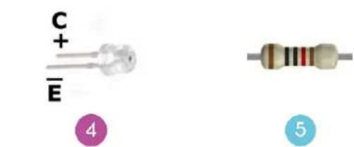
- Red (anode +)
- Ground (cathode -) - longest leg
- Green (anode +)
- Blue (anode +)
text_image
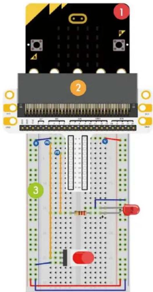
Diagram of an electronic circuit board layout with labeled components and wiring connectionsWe are going to make an RGB LED gradually shift its light among red, green and blue.
Place the necessary components on the breadboard as shown.
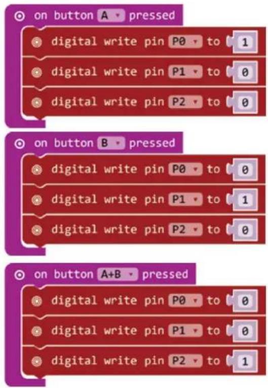
Have a look at the code below.
text_image
on button A - pressed digital write pin P0 to 1 digital write pin P1 to 0 digital write pin P2 to 0 on button B - pressed digital write pin P0 to 0 digital write pin P1 to 1 digital write pin P2 to 0 on button A+B - pressed digital write pin P0 to 0 digital write pin P1 to 0 digital write pin P2 to 1- Drag and drop the code blocks to form the code as shown.
You can find the on button A pressed block in Input in the Code Drawer. You can find the digital write pin P0 to 0 block in Pins in the Code Drawer.
Select the A option in the on button A pressed block.
Drag 3 digital write pin P0 to 0 blocks and insert them in the on button A pressed block.
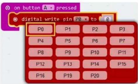
Set pin P0 in the first digital write pin P0 to 0 block, and set value 0 to 1 (red LED on).
Set pin P1 in the second digital write pin P0 to 0 block, and set value to 0 (green LED off).
Set pin P2 in the third digital write pin P0 to 0 block, and set value to 0 (blue LED off).
text_image
on button A pressed digital write pin P0 to 0 P0 P1 P2 P3 P4 P5 P6 P7 P8 P9 P10 P11 P12 P13 P14 P15 P16 P19 P20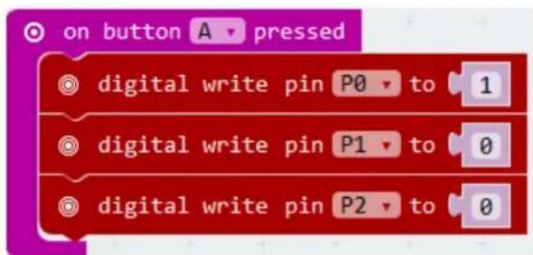
text_image
on button A pressed digital write pin P0 to 1 digital write pin P1 to 0 digital write pin P2 to 0| 2. | Similarly, compile the twoon button B/A+Bpressedblocks to form the complete code. |
| 3. | When complete, we compile the programme and generate a hex. file. Click on the download button and save the hex. file to the Downloads folder →C:\downloads. This hex. file is ready to upload to the micro:bit.Plug the micro:bit into a USB port. The, drag and drop the hex. file onto the micro:bit removable device to upload the programme. |
Press button A to light the red LED, press button B to light the green LED, press buttons A and B simultaneously to light the blue LED. Now, how would you realize a soft gradient RGB light?
5.6 Self-Locking Switch
1x micro:bit board
2 1x micro:bit breadboard adapter
3 1x breadboard
4 1x 100 Ω resistor (brown/black/brown/gold)
5 1x red LED (polarisation: anode (+) = long leg, cathode (-) = short leg)
6 1x self-locking or bi-stable switch
text_image
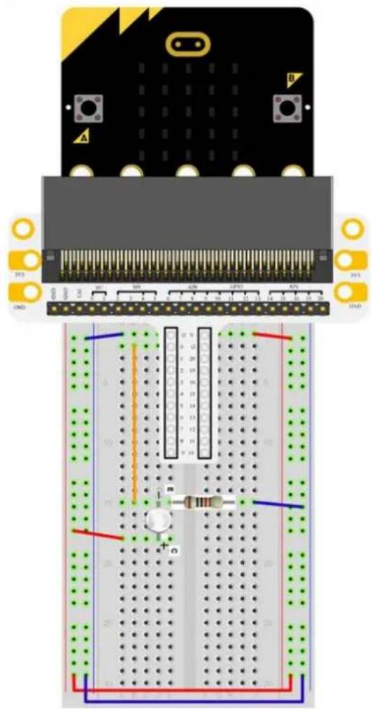
Illustration of three types of resistors with numbered labels: resistor 4, LED, and LED bulb.We are going to read out the ambient temperature (data) of the analogue temperature sensor and display the data to the micro:bit.
Place the necessary components on the breadboard as shown.
Have a look at the code below.
text_image
Diagram of an electronic circuit board with labeled components and wiring, including a breadboard layout and indicator lights.
text_image
on start set pin P0 ▼ to emit edge ▼ events set pull pin P0 ▼ to up ▼ on event from MICROBIT_ID_IO_P0 ▼ with value MICROBIT_PIN_EVT_FALL ▼ digital write pin P2 ▼ to 1 on event from MICROBIT_ID_IO_P0 ▼ with value MICROBIT_PIN_EVT_RISE ▼ digital write pin P2 ▼ to 0| 1. | Drag and drop the code blocks to form the code as shown.You can find the set pin P0 to emit edge events and set pull P0 to up blocks in Pins → More in the Code Drawer. You can find the on event from MICROBIT...EVT_FALL/RISE blocks in Control in the Code Drawer. |
| 2. | Set the events type on edge. Set the pull pin to P0 and to up. |
| 3. | Now, make a fall event block. Drag and drop the on event from MICROBIT...EVT°FALL block below the on start block. Click on the first arrow and select the MICROBIT_ID_IO_P0 option in the pull-down menu. Click on the second arrow and select the MICROBIT_PIN_EVENT_FALL option in the pull-down menu.Drag and drop the digital write pin P0 to 0 block into the event block. Set pin P0 to P2 and set 0 to 1. You can find the digital write pin P0 to 0 block in Pins in the Code Drawer. |
| 4. | Do the same for the second event block. Instead, click on the second arrow and select the MICROBIT_PIN_EVENT_RISE option in the pull-down menu. Also, set pin P0 to P2 of the digital write pin P0 to 0 block and set the value to 0. |
| 5. | When complete, we compile the programme and generate a hex. file. Click on the download button and save the hex. file to the Downloads folder → C:\downloads. This hex. file is ready to upload to the micro:bit.Plug the micro:bit into a USB port. The, drag and drop the hex. file onto the micro:bit removable device to upload the programme. |
Press down the self-locking switch and the LED will switch on. Press again to switch off the LED. Now, how would you control the micro:bit display with this self-locking switch?
5.7 Temperature Sensor
1x micro:bit board
2 1x micro:bit breadboard adapter
3 1x breadboard
4 1x TMP36 temperature sensor
4
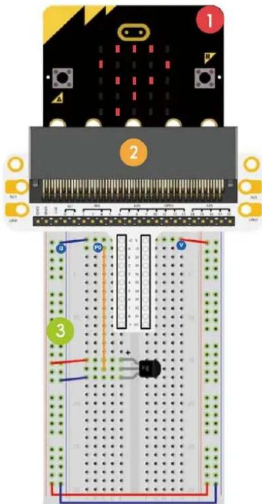
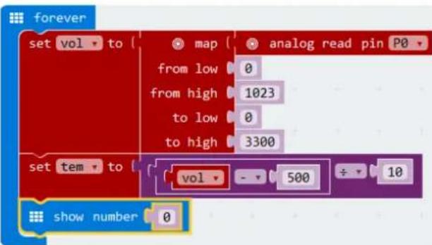
We are going to read out the ambient temperature (data) of the analogue temperature sensor and display the data to the micro:bit.
Place the necessary components on the breadboard as shown.
text_image
Diagram of an electronic circuit board with labeled components and wiring, showing connections between pins and a breadboard layout.Have a look at the code below.
text_image
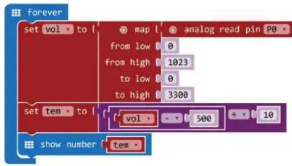
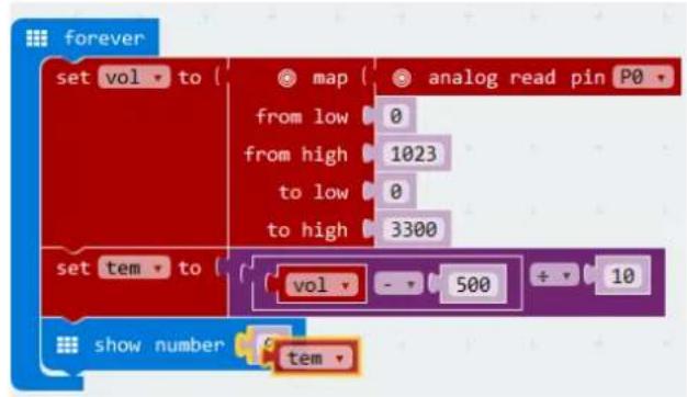
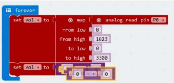
forever set vol to { map from low 0 from high 1023 to low 0 to high 3300 set tem to { vol - 500 ÷ 10 show number tem -- Drag and drop the code blocks to form the code as shown.
You can find the set item to block in Variables in the Code Drawer. You can find the map/from low/from high/to low/to high and analog read pin blocks in Pins in the Code Drawer. You can find the mathematical function minus and divide in Math in the Code Drawer. You can find the show number block in Basic in the Code Drawer.
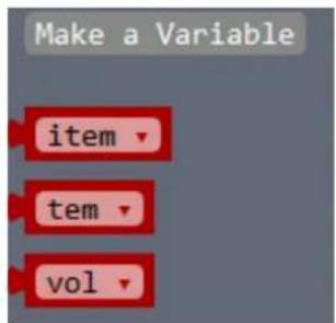
- First, we make two variables. Go to Variables in the Code Drawer and click on Make a Variable.
New variable name:

text_image
CalVal Ok Cancel ×Enter vol in the window and click Ok. Enter tem in the window and click Ok.
You will see two new variables under Variables in the Code Drawer.
text_image
Make a Variable item tem volWe will need these variables later to save the data in a register.
Drag and drop the set item to block in the forever block and select the vol option via the arrow.
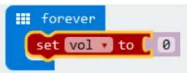
text_image
forever set vol to 0Next, we drag and drop the map/from low/from high/to low/to high block over the 0 next to the set item to block.
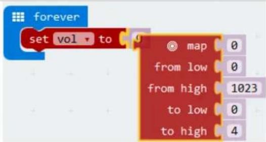
text_image
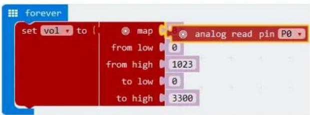
forever set vol to map from low from high to low to high 0 0 1023 0 4Drag and drop the analog read pin block next to the map/from low/from high/to low/to high block and set the to high value 4 to 3300.
text_image
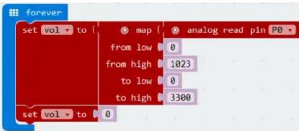
forever set vol to ( map from low 0 from high 1023 to low 0 to high 3300 analog read pin P0Now, we drag and drop a set item to block under the first block. Change the variable item to vol via the arrow.
text_image
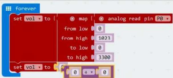
forever set vol to { map analog read pin P0 from low 0 from high 1023 to low 0 to high 3300 set vol to 0The measured voltage in mV via analog read pin P0 is an 8-bit value of 0-1023 (0-3.3 V) and is mapped from a low value (0 or 0 V) to a high value (3300 mV or 3.3 V). The measured voltage (mV) is saved in the vol variable.

text_image
forever set vol to { map analog read pin P0 from low 0 from high 1023 to low 0 to high 3300Now, we write a formula to convert the measured voltage into a temperature:
$$ \text { Temperature } (^ {\circ} C) = \frac {(\text { Output voltage (mV) } - 5 0 0)}{1 0} $$
In this formula, the output voltage is the vol variable (measured through the TMP36 sensor). The result of the formula will be saved in the tem variable.
Let's write the formula with blocks. Drag and drop the mathematical function divide over the 0 value of the set vol to block.
text_image
forever set vol to map analog read pin P0 from low 0 from high 1023 to low 0 to high 3300 set vol to 0 + 0Drag and drop the mathematical function minus over the first 0 of the mathematical function divide.
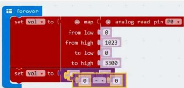
text_image
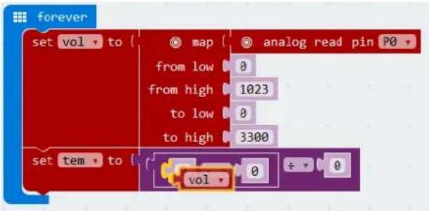
forever set vol to map analog read pin P0 from low 0 from high 1023 to low 0 to high 3300 set vol to 0 - - 0Now, set the second variable from vol to tem, and drag and drop the vol variable over the first 0 of the mathematical function minus. The variable vol can be found in Variables in the Code Drawer.
text_image
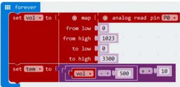
forever set vol to { map { analog read pin P0 from low 0 from high 1023 to low 0 to high 3300 set tem to { vol 0 ÷ 0Set the value 0 of the mathematical function minus to 500. Also, Set the value of the mathematical function divide to 10
text_image
forever set vol to { map analog read pin P0 from low 0 from high 1023 to low 0 to high 3300 set tem to vol - 500 + 10Drag and drop the show number block under the set tem to block.
text_image
forever set vol to { map analog read pin P0 from low 0 from high 1023 to low 0 to high 3300 set tem to vol - 500 ÷ 10 show number 0Finally, drag and drop the tem variable over the value 0 of the show number block.
flowchart
graph TD
    A["set vol to"] --> B["map"]
    B --> C["analog read pin P0"]
    D["from low"] --> E["0"]
    F["from high"] --> G["1023"]
    H["to low"] --> I["0"]
    J["to high"] --> K["3300"]
    L["set tem to"] --> M["vol"]
    M --> N["500"]
    N --> O["10"]
    P["show number"] --> Q["tem"]
You have written the code!
- When complete, we compile the programme and generate a hex. file. Click on the download button and save the hex. file to the Downloads folder → C:\downloads. This hex. file is ready to upload to the micro:bit. Plug the micro:bit into a USB port. The, drag and drop the hex. file onto the micro:bit removable device to upload the programme.
You will see the LED beads flash alternatively. Now, how would you display the temperature in degrees Fahrenheit?
5.8 Servo

1x micro:bit board
1x micro:bit breadboard adapter
1x breadboard
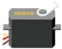
1x mini servo
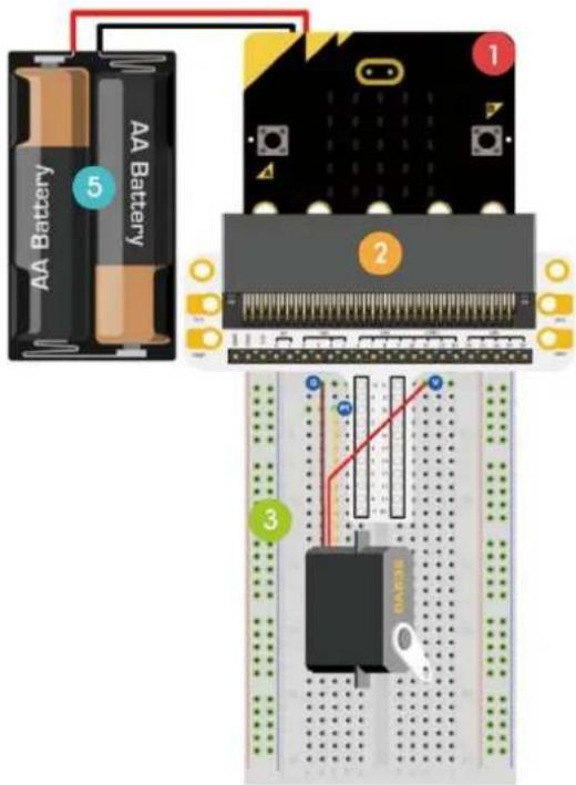
1x battery holder with 2x AA 1.5 V battery
4
text_image
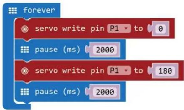
AA Battery 5 AA Battery 1 2 3We are going to make a servo rotate continuously within a travel range (0-180°).
Place the necessary components on the breadboard as shown.
Have a look at the code below.
flowchart
graph TD
    A["forever"] --> B["servo write pin P1 to 0"]
    B --> C["pause (ms) 2000"]
    C --> D["servo write pin P1 to 180"]
    D --> E["pause (ms) 2000"]
| 1. | Drag and drop the code blocks to form the code as shown.You can find theservowrite pin P0 to 180block in Pinsin the Code Drawer. You can find theforeverandpause (ms) 100in Basicin the Code Drawer. |
| 2. | Set P0 to P1and set the value to 0. |
| 3. | Set thepauseto 2000 ms. |
| 4. | Set P0 to P1. Also, set the value 0 to 180. |
| 5. | Set thepauseto 2000 ms. |
| 6. | When complete, we compile the programme and generate a hex. file. Click on the download button and save the hex. file to the Downloads folder → C:\downloads. This hex. file is ready to upload to the micro:bit.Plug the micro:bit into a USB port. The, drag and drop the hex. file onto the micro:bit removable device to upload the programme. |
We can see the servo rotating from 0 to 180 degrees. Now, how would you make a dial thermometer with a temperature sensor and servo?
5.9 Buzzer
1
1x micro:bit board
2
1x micro:bit breadboard adapter
3
1x breadboard
4
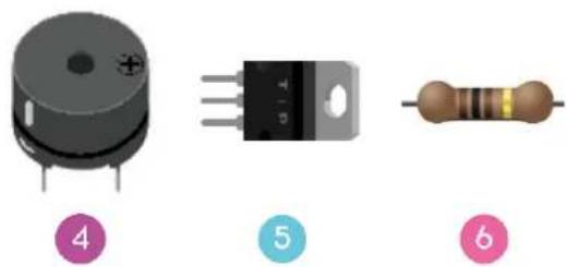
1x mini speaker
5
1x N-channel MOSFET
6
1x 100 Ω resistor (brown/black/brown/gold)
natural_image
Three electronic components: a cylindrical capacitor, a rectangular component with three leads, and a resistor, all labeled with numbers 4, 5, and 6 (no text or symbols on the components themselves)We are going to drive a buzzer.
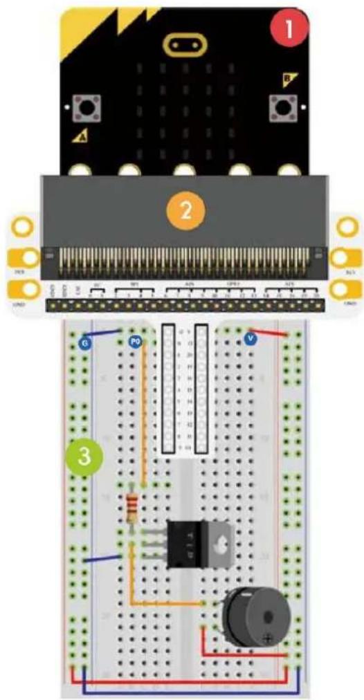
Place the necessary components on the breadboard as shown.
text_image
Diagram of an electronic circuit board layout with labeled components and wiring connectionsHave a look at the code below.
flowchart
graph TD
    A["forever"] --> B["ring tone (Hz) Middle C"]
    A --> C["pause (ms) 100"]
    A --> D["ring tone (Hz) Middle E"]
    A --> E["pause (ms) 100"]
    A --> F["ring tone (Hz) Middle G"]
    A --> G["pause (ms) 100"]
    A --> H["ring tone (Hz) Middle E"]
    A --> I["pause (ms) 100"]
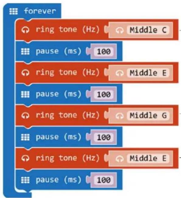
| 1. | Drag and drop the code blocks to form the code as shown.You can find the forever and pause (ms) 100 in Basic in the Code Drawer. You can find the ring tone (Hz) block in Music in the Code Drawer. |
| 2. | Set the first ring tone (Hz) to middle C. To do so, click the text box and select the corresponding piano key.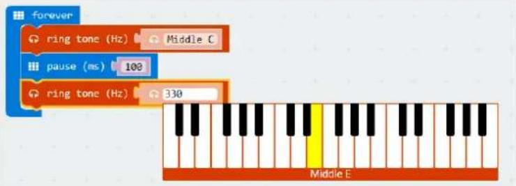 You will also hear the corresponding tone. You will also hear the corresponding tone. |
| 3. | Set the pause to 100 ms. |
| 4. | Do so for the rest of the ring tones and pauses. |
| 5. | When complete, we compile the programme and generate a hex. file. Click on the download button and save the hex. file to the Downloads folder → C:\downloads. This hex. file is ready to upload to the micro:bit.Plug the micro:bit into a USB port. The, drag and drop the hex. file onto the micro:bit removable device to upload the programme. |
We can hear a sound from the buzzer. Now, how would you programme your favourite nursery rhyme?
5.10 Motor
1
1x micro:bit board
2
1x micro:bit breadboard adapter
3
1x breadboard
4
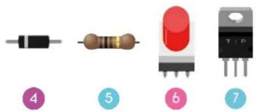
1x diode
5
1x 100 Ω resistor (brown/black/brown/gold)
6
1x self-locking or bi-stable switch
7
1x N-channel MOSFET
8
1x mini motor
9
1x battery holder with 2x AA 1.5 V battery
text_image
Image showing seven labeled electronic components: resistor, coil, LED, and T-12 transistor.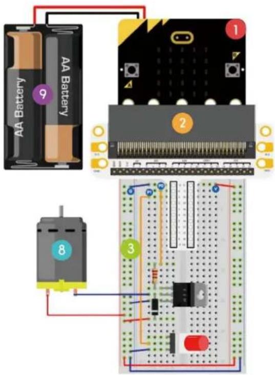
text_image
AA Battery f Battery 9 1 2 8 3We are going to use a switch to control the start and stop of a motor.
Place the necessary components on the breadboard as shown.
Have a look at the code below.
flowchart
graph TD
    A["on start"] --> B["digital write pin P0 to 0"]
    A --> C["set pull pin P1 to up"]
    D["forever"] --> E{if digital read pin P1 = 0}
    E --> F["then digital write pin P0 to 1"]
    E --> G["else digital write pin P0 to 0"]
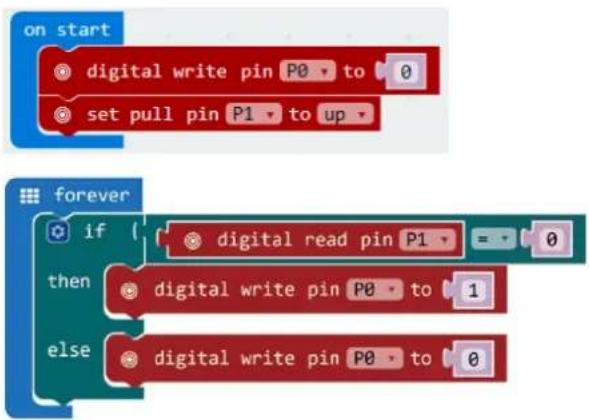
| 1. | Drag and drop the code blocks to form the code as shown. |
| 2. | The on start block runs only once to start the programme. |
| 3. | Set the value of P0 to 0. |
| 4. | Set the pull pin block to P1 and up. |
| 5. | Within forever, set the digital read pin to P1. Set the mathematical function equal to 0.In reality, this is the scheme. The pull-up resistor must not be added as hardware onto the breadboard. The pull-up function is programmed (see step 3-4) in the code and replaces the need of the resistor on the breadboard.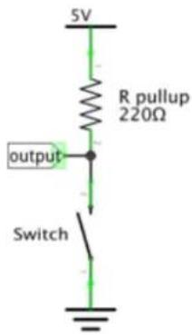 |
| 6. | Once the switch is pressed, set high voltage to P0. Set value 0 to 1 (5 V).The motor starts running. |
| 7. | Once the switch is released, set low voltage to P0. Set value to 0. The motor stops running. |
| 8. | When complete, we compile the programme and generate a hex. file. Click on the download button and save the hex. file to the Downloads folder → C:\downloads. This hex. file is ready to upload to the micro:bit.Plug the micro:bit into a USB port. The, drag and drop the hex. file onto the micro:bit removable device to upload the programme. |
Press the switch to run the motor and release it to stop. Now, how would you use a trimpot to control the motor speed?
Note: Since the micro:bit voltage is 3.3 V only, it may not be enough to support the fan. To make the fan run, you may have to rotate the blade to help it start.
5.11 Rainbow LED
1
1x micro:bit board
2
1x micro:bit breadboard adapter
3
1x breadboard
4
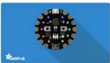
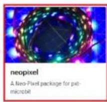
1x RGB LED ring
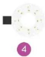
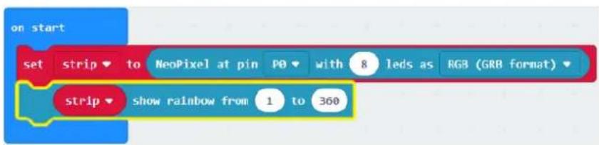
We are going to drive eight RGB LEDs in a ring and realize a gradual rainbow.
Place the necessary components on the breadboard as shown.
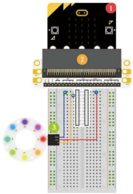
text_image
Diagram of a breadboard with labeled components and a color palette, showing pin connections and wiring paths.Have a look at the code below.
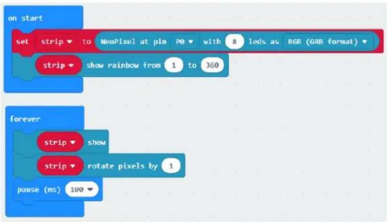
text_image
on start set strip to NeoPixel at pin PO with 8 leds as RGB (GRB format) strip show rainbow from 1 to 360 forever strip show strip rotate pixels by 1 pause (ms) 100- Drag and drop the code blocks to form the code as shown.
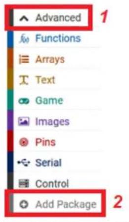
- Search and add the NeoPixel library.
Go to Advanced → Add Package (Extensions) and enter NeoPixel.
text_image
Advanced Functions Arrays Text Game Images Pins Serial Control Add PackageAdd Package... ?

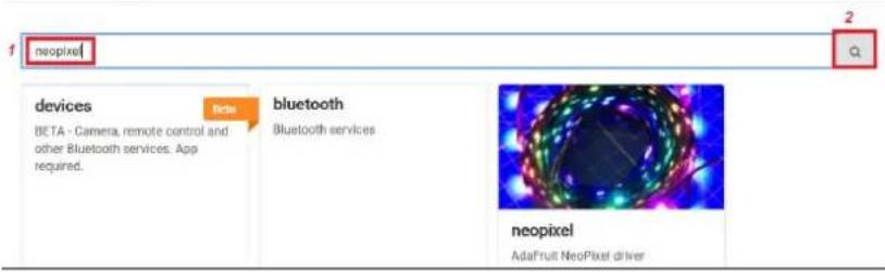
text_image
1 neopixel 2 3 devices BETA - Camera, remote control and other Bluetooth services. App required. New bluetooth Bluetooth services neopixel AdaFruit NeoPixel driverNext, select the NeoPixel library.
Add Package... ?

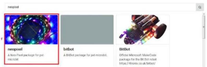
text_image
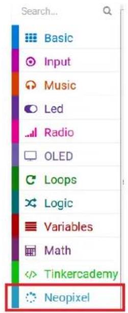
neopixel neopixel A Neo-Pixel package for pxt-microbit bitbot A BitBot package for pxt-microbit. BitBot Official Microsoft MakeCode package for the Bit-Bot robot https://tronix.co.uk/bitbot/Now, the library is downloaded and added to the Code Drawer.
text_image
Search... Basic Input Music Led Radio OLED Loops Logic Variables MathYou can find the NeoPixel at pin P0 with 24 leds, item show rainbow from 1 to 360, item show and items rotate pixels by 1 blocks in NeoPixel in the Code Drawer.
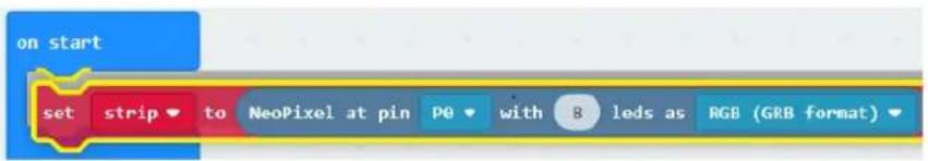
- Drag and drop the set strip to NeoPixel at pin P0 with 24 leds as RGB (GRB format) block in the on start block. Set pin to P0 and the value 24 to 8 (we have 8 LEDs on the LED ring).
text_image
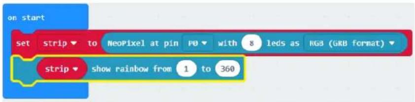
on start set strip to NeoPixel at pin PO with 8 leds as RGB (GRB format)- Now, drag and drop the set strip to rainbow from 1 to 360 block under the set strip to NeoPixel at pin P0 block.
text_image
on start set strip to NeoPixel at pin PO with 8 leds as RGB (GRB format) strip show rainbow from 1 to 360-
Complete the code according to the example.
-
When complete, we compile the programme and generate a hex. file. Click on the download button and save the hex. file to the Downloads folder → C:\downloads. This hex. file is ready to upload to the micro:bit. Plug the micro:bit into a USB port. The, drag and drop the hex. file onto the micro:bit removable device to upload the programme.
We can see rainbow rotating on the LED ring. Now, how would you make the ring blink like an eye?
Use this device with original accessories only. Velleman nv cannot be held responsible in the event of damage or injury resulting from (incorrect) use of this device. For more info concerning this product and the latest version of this manual, please visit our website www.velleman.eu. The information in this manual is subject to change without prior notice.
© COPYRIGHT NOTICE
The copyright to this manual is owned by Velleman nv. All worldwide rights reserved. No part of this manual may be copied, reproduced, translated or reduced to any electronic medium or otherwise without the prior written consent of the copyright holder.
HANDLEIDING
1. Inleiding
text_image
Diagram of a breadboard with labeled components and colored wires, showing connections between pins 1, 2, and 3.
Hands on computing education
Microsoft MakeCode brings computer science to life for all students with fun projects, immediate results, and both block and text editors for learners at different levels.

natural_image
Illustration of a microchip with circuit board and pin (no text or symbols)micro:bit
Start coding with microbit >
natural_image
Circular electronic circuit board with multiple LEDs and components, set against a blue background (no readable text or symbols)Circuit Playground Express
Start coding with Circuit Playground Express >

natural_image
Pixelated white icon of a sitting figure on a green background (no text or symbols)Minecraft
Start coding with Minecraft >
text_image
micro:bit Let's Code Ideas Meet micro:bit Teach Buy English- Power your imagination with code Did you know that you can code your BBC micro:bit using Blocks, JavaScript, and Python? If you have never used a BBC micro:bit try our Quick Start Guide. Microsoft let's code Reference Lessons JavaScript Blocks Editor The micro:bit's JavaScript Blocks editor makes it easy to program your BBC micro:bit in Blocks and JavaScript. Powered by MakeCode. If you have any issues accessing the editor, check that it isn't blocked in your school. If you need some inspiration then check out these Projects. Let's Codetext_image
New Project Import Blocks JavaScript Support Getting started Projects Reference Blocks JavaScript Hardware Buy
text_image
Microsoft Project Settings Extensions Delete Project Report Abuse... Language High Contrast On Reset About...text_image
1 Select Basic show number 0 show leds Music Loops Logic Variables Math Radio Advanced Getting Started 2 Drag A show string Hello Everybody A show string Hello! Display text on the screen one character at a time if the string fits on the screen (i.e. is one writer), does not scroll. C forever pause (ms) 100 3 Click to Edit| 1 | Selecteren |
| 2 | Slepen |
text_image
on start show string "Hello Everybody"Test de code in de simulator!
Say Hello!
flowchart
Game control flowchart for showing numbers and LED indicators, including live/stop states and LED display statestext_image
show number 2 pause (ms) 100
text_image
show number 2 pause (ms) 100
text_image
show number 2 pause (ms) 100 3Op de micro:bit testen
text_image
Diagram of a breadboard layout with labeled components and colored wires, showing connections and wiring paths.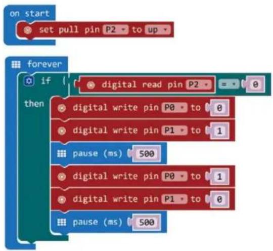
flowchart
graph TD
    A["on start"] --> B["set pull pin P2 to up"]
    C["forever"] --> D{if digital read pin P2}
    D --> E["0"]
    D --> F["then digital write pin P0 to 0"]
    D --> G["0"]
    D --> H["0"]
    D --> I["0"]
    D --> J["0"]
    D --> K["0"]
    D --> L["pause (ms) 500"]
    D --> M["0"]
    D --> N["0"]
    D --> O["0"]
    D --> P["0"]
    D --> Q["0"]
    D --> R["pause (ms) 500"]
1.
text_image
Diagram of an electronic circuit board with labeled components and wiring, showing connections between a breadboard and a PCB.text_image
plot bar graph of up to analog read pin P0 1023Kort pootje = collector
Positieve anode
Lang pootje = zender
Negatieve cathode
text_image
Diagram of a breadboard layout with labeled components and wiring, showing pin connections and color-coded wires.text_image
on start set CalVal to analog read pin P0 ✓ CalVal item PhoVal Rename variable... Delete the "CalVal" variable on start set CalVal to analog read pin P0- Selecteer de variabele CalVal en stel analog read pin in op P0.
text_image
on start set CalVal to analog read pin P0text_image
Diagram of an electronic circuit board layout with labeled components and wiring connectionstext_image
on button A · pressed digital write pin P0 to 1 digital write pin P1 to 0 digital write pin P2 to 0 on button B · pressed digital write pin P0 to 0 digital write pin P1 to 1 digital write pin P2 to 0 on button A+B · pressed digital write pin P0 to 0 digital write pin P1 to 0 digital write pin P2 to 1text_image
on button A pressed digital write pin P0 to 1 digital write pin P1 to 0 digital write pin P2 to 0natural_image
Three labeled electronic components: a resistor, a light bulb, and a red LED (no text or symbols present)text_image
Diagram of an electronic circuit board with labeled components and wiring, including a breadboard layout and LED indicators.
text_image
on start set pin P0 ▼ to emit edge ▼ events set pull pin P0 ▼ to up ▼ on event from MICROBIT_ID_IO_P0 ▼ with value MICROBIT_PIN_EVT_FALL ▼ digital write pin P2 ▼ to 1 on event from MICROBIT_ID_IO_P0 ▼ with value MICROBIT_PIN_EVT_RISE ▼ digital write pin P2 ▼ to 0text_image
Diagram of a breadboard layout with labeled components and wiring, showing pin connections and color-coded wires.text_image
forever set vol to { map from low 0 from high 1023 to low 0 to high 3300 set tem to { vol - 500 ÷ 10 show number tem -text_image
forever set vol to 0text_image
forever set vol to map from low from high to low to high 0 0 1023 0 4text_image
set vol to { map from low 0 from high 1023 to low 0 to high 3300 analog read pin P0text_image
forever set vol to ( map ( analog read pin P0 ) from low 0 from high 1023 to low 0 to high 3300 set vol to 0text_image
set vol to map from low 0 from high 1023 to low 0 to high 3300 analog read pin P0text_image
forever set vol to map analog read pin P0 from low 0 from high 1023 to low 0 to high 3300 set vol to 0 + 0Sleep het blok mathematical function minus (-) over de eerst 0 van de mathematical function divide (/).
text_image
forever set vol to ( map ( analog read pin P0 ) from low 0 from high 1023 to low 0 to high 3300 set vol to ( 0 - - 0text_image
forever set vol to { map analog read pin P0 from low 0 from high 1023 to low 0 to high 3300 set tem to vol 0 ÷ 0text_image
forever set vol to { map { analog read pin P0 } from low 0 from high 1023 to low 0 to high 3300 set tem to { vol - 500 + 10text_image
forever set vol to { map { analog read pin P0 } from low 0 from high 1023 to low 0 to high 3300 set tem to { vol - 500 ÷ 10 show number 0text_image
forever set vol to { map { analog read pin P0 from low 0 from high 1023 to low 0 to high 3300 } } set tem to { vol - 500 + 10 } show number temtext_image
AA Battery 5 AA Battery 1 2 3
flowchart
graph TD
    A["forever"] --> B["servo write pin P1 to 0"]
    B --> C["pause (ms) 2000"]
    C --> D["servo write pin P1 to 180"]
    D --> E["pause (ms) 2000"]
natural_image
Three electronic components: a cylindrical capacitor, a rectangular transistor, and a resistor, each labeled with a number (4, 5, 6) but without any visible text or symbols.text_image
Diagram of an electronic circuit board with labeled components and wiring, including a breadboard layout and component layout.flowchart
graph TD
    A["ring tone (Hz)"] --> B[" Middle C "]
    C["pause (ms)"] --> D[" 100 "]
    E["ring tone (Hz)"] --> F[" Middle E "]
    G["pause (ms)"] --> H[" 100 "]
    I["ring tone (Hz)"] --> J[" Middle G "]
    K["pause (ms)"] --> L[" 100 "]
    M["ring tone (Hz)"] --> N[" Middle E "]
    O["pause (ms)"] --> P[" 100 "]
text_image
Diagram showing seven types of electronic components with numbered labels: resistor, resistor coil, LED, and T-12 transistor.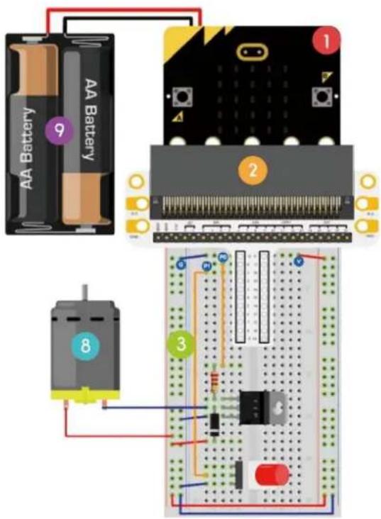
text_image
AA Battery f Battery 9 1 2 8 3flowchart
graph TD
    A["on start"] --> B["digital write pin P0 to 0"]
    A --> C["set pull pin P1 to up"]
    D["forever"] --> E{if digital read pin P1 = 0}
    E --> F["then digital write pin P0 to 1"]
    E --> G["else digital write pin P0 to 0"]
text_image
Diagram of a breadboard layout with labeled components and color-coded pin indicatorstext_image
on start set strip to NeoPixel at pin PO with 8 leds as RGB (GRB format) strip show rainbow from 1 to 360 forever strip show strip rotate pixels by 1 pause (ms) 100text_image
neopixel devices BETA - Camera, remote control and other Bluetooth services. App required. beta bluetooth Bluetooth services neopixel AdaFruit NeoPixel driverSelecteer de NeoPixel-bibliotheek.
Add Package... ?
×
neopixel
Q
text_image
neopixel A Neo-Pixel package for pet- microbit
bitbot
BitBot
A BitBot package for gwt-microbit.
Official Microsoft MakeCode package for the BitBot robot https://4tronix.co.uk/bitbot/
text_image
on start set strip to NeoPixel at pin PO with 8 leds as RGB (GRB format)text_image
on start set strip to NeoPixel at pin PO with 8 leds as RGB (GRB format) strip show rainbow from 1 to 360text_image
Diagram of a breadboard with labeled components and colored wires, showing connections between pins 1, 2, and 3.
Hands on computing education
Microsoft MakeCode brings computer science to life for all students with fun projects, immediate results, and both block and text editors for learners at different levels.
natural_image
Illustration of a micro-bit integrated circuit board with black and yellow components (no text or symbols)micro:bit Start coding with micro:bit >
natural_image
Circular electronic circuit board with colored pins on a blue background (no text or symbols visible)Circuit Playground Express Start coding with Circuit Playground Express >

natural_image
Simple white icon of a person sitting on a chair against a green background (no text or symbols)Minecraft Start coding with Minecraft >
text_image
micro:bit Let's Code Ideas Meet micro:bit Teach Buy English- Power your imagination with code Did you know that you can code your BBC micro:bit using Blocks, JavaScript, and Python? If you have never used a BBC micro:bit try our Quick Start Guide. Microsoft micro:bit Programs Show strong Show strong Show strong Show strong Show strong Show strong Show strong Show strong Show strong Show strong Show strong Show strong Show strong Show strong Show strong Show strong Show strong Show strong Show strong Show strong Show strong Show strong Show strong Show strong Show strong Show strong Show strong Show strong Show strong Show strong Show strong Show strong Show strong Show strong (100%) Show strong (100%) Show strong (100%) Show strong (100%) Show strong (100%) Show strong (100%) Show strong (100%) Show strong (100%) Show strong (100%) Show strong (100%) Show strong (100%) Show strong (100%) Show strong (100%) Show strong (80%) Show strong (80%) Show strong (80%) Show strong (80%) Show strong (80%) Show strong (80%) Show strong (80%) Show strong (80%) Show strong (80%) Show strong (80%) Show strong (80%) Show strong (80%) Show strong (80%) Show strong (80%) Show strong (80% Let's Code Reference Lessonstext_image
New Project Import Blocks JavaScript Support Getting started Projects Reference Blocks JavaScript Hardware Buytext_image
Microsoft Project Settings Extensions Delete Project Report Abuse... Language High Contrast On Reset About...text_image
1 Select Basic show number 0 Input Show leds Music Led Loops Logic Variables Math Radio Advanced Getting Started 2 Drag A show string → Hello Everybody A show string → Hello! Dress the line on the display one character at a key. If the string fits on the screen (i.e. is one letter), does not scroll. C forever ○ pause (ms) 100 3 Click to Edit A show string → Hello Everybodytext_image
on start show string "Hello Everybody"text_image
show number 2 pause (ms) 100
text_image
show number 2 pause (ms) 100Tester sur le micro:bit
text_image
Diagram of a breadboard layout with labeled components and wiring, showing circuit connections and component placements.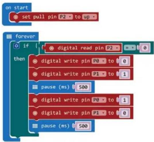
flowchart
graph TD
    A["on start"] --> B["set pull pin P2 to up"]
    C["forever"] --> D{if digital read pin P2 = 0}
    D -->|Yes| E["digital write pin P0 to 0"]
    D -->|No| F["digital write pin P1 to 1"]
    E --> G["pause (ms) 500"]
    F --> H["digital write pin P0 to 1"]
    H --> I["digital write pin P1 to 0"]
    I --> J["pause (ms) 500"]
1.
text_image
Diagram of a breadboard layout with labeled components and colored wires, showing connections and measurement scales.text_image
plot bar graph of up to analog read pin P0 1023text_image
Diagram of a breadboard layout with labeled components and wiring, showing pin connections and color-coded wires.text_image
on start set CalVal to analog read pin P0 ✓ CalVal item PhoVal Rename variable... Delete the "CalVal" variable on start set CalVal to analog read pin P0text_image
on start set CalVal to analog read pin P01x LED RGB (cathode commune)
5
text_image
Diagram of an electronic circuit board layout with labeled components and wiring connectionstext_image
on button A · pressed digital write pin P0 to 1 digital write pin P1 to 0 digital write pin P2 to 0 on button B · pressed digital write pin P0 to 0 digital write pin P1 to 1 digital write pin P2 to 0 on button A+B · pressed digital write pin P0 to 0 digital write pin P1 to 0 digital write pin P2 to 1text_image
on button A pressed digital write pin P0 to 1 digital write pin P1 to 0 digital write pin P2 to 0text_image
Three labeled electronic components: a resistor, a light bulb, and a red LED with three numbered pins.text_image
Diagram of an electronic circuit board with labeled components and wiring, including a breadboard layout and LED indicators.
text_image
on start set pin P0 ▼ to emit edge ▼ events set pull pin P0 ▼ to up ▼ on event from MICROBIT_ID_IO_P0 ▼ with value MICROBIT_PIN_EVT_FALL ▼ digital write pin P2 ▼ to 1 on event from MICROBIT_ID_IO_P0 ▼ with value MICROBIT_PIN_EVT_RISE ▼ digital write pin P2 ▼ to 0text_image
Diagram of a breadboard layout with labeled components and wiring, showing circuit board layout and component placement.text_image
forever set vol to { map from low 0 from high 1023 to low 0 to high 3300 set tem to { vol - 500 ÷ 10 show number tem -text_image
forever set vol to 0text_image
forever set vol to map from low from high to low to high 0 0 1023 0 4text_image
forever set vol to ( map from low 0 from high 1023 to low 0 to high 3300 analog read pin P0text_image
forever set vol to { map { analog read pin P0 from low 0 from high 1023 to low 0 to high 3300 set vol to 0text_image
set vol to map from low 0 from high 1023 to low 0 to high 3300 analog read pin P0text_image
forever set vol to map analog read pin P0 from low 0 from high 1023 to low 0 to high 3300 set vol to 0 + 0text_image
forever set vol to ( map ( analog read pin P0 ) from low 0 from high 1023 to low 0 to high 3300 set vol to ( 0 - - 0text_image
forever set vol to { map analog read pin P0 from low 0 from high 1023 to low 0 to high 3300 set tem to vol 0 ÷ 0text_image
forever set vol to { map analog read pin P0 from low 0 from high 1023 to low 0 to high 3300 set tem to vol - 500 + 10text_image
forever set vol to { map analog read pin P0 from low 0 from high 1023 to low 0 to high 3300 set tem to vol - 500 ÷ 10 show number 0text_image
forever set vol to { map { analog read pin P0 from low 0 from high 1023 to low 0 to high 3300 } } set tem to { vol - 500 + 10 } show number temtext_image
AA Battery 5 AA Battery 1 2 3natural_image
Three electronic components: a cylindrical capacitor, a rectangular component with three leads, and a resistor, all shown with colored circular labels (no text or symbols on the components themselves)text_image
Diagram of an electronic circuit board with labeled components and wiring connectionsflowchart
graph TD
    A["ring tone (Hz)"] --> B[" Middle C "]
    C["pause (ms)"] --> D[" 100 "]
    E["ring tone (Hz)"] --> F[" Middle E "]
    G["pause (ms)"] --> H[" 100 "]
    I["ring tone (Hz)"] --> J[" Middle G "]
    K["pause (ms)"] --> L[" 100 "]
    M["ring tone (Hz)"] --> N[" Middle E "]
    O["pause (ms)"] --> P[" 100 "]
text_image
Image showing seven labeled electronic components: resistor, resistor coil, LED, and T-10 transistor.
text_image
AA Battery f 9 AA Battery 1 2 8 3flowchart
graph TD
    A["on start"] --> B["digital write pin P0 to 0"]
    A --> C["set pull pin P1 to up"]
    D["forever"] --> E{if digital read pin P1 = 0}
    E --> F["then digital write pin P0 to 1"]
    E --> G["else digital write pin P0 to 0"]
text_image
Diagram of a breadboard with labeled components and a color palette, showing connections between pins and a circuit board.text_image
on start set strip to NeoPixel at pin PO with 8 leds as RGB (GRB format) strip show rainbow from 1 to 360 forever strip show strip rotate pixels by 1 pause (ms) 100text_image
neopixel devices BETA - Camera, remote control and other Bluetooth services. App required. beta bluetooth Bluetooth services neopixel AdaFruit NeoPixel driverA BitBot package for pwt-microbit.
Official Microsoft MakeCode package for the BitBot robot https://4tronix.co.uk/bitbot/
text_image
on start set strip to NeoPixel at pin P0 with 8 leds as RGB (GRB format)- Glisser-déposer le bloc set strip to rainbow from 1 to 360 sous le bloc set strip to NeoPixel at pin P0.
text_image
on start set strip to NeoPixel at pin PO with 8 leds as RGB (GRB format) strip show rainbow from 1 to 360text_image
Diagram of a breadboard with labeled components and colored wires, showing connections between pins 1, 2, and 3.
Hands on computing education
Microsoft MakeCode brings computer science to life for all students with fun projects, immediate results, and both block and text editions for learners at different levels.

natural_image
Illustration of a micro-bit microphone with circuit board and pin symbols (no text or labels)micro:bit
Start coding with microbit >

natural_image
Circular electronic circuit board with colorful components on a blue background (no readable text or symbols)Circuit Playground Express
Start coding with Circuit Playground Express

natural_image
Simple white icon of a person sitting on a chair on a green background (no text or symbols)Minecraft
Start coding with Minecraft >
text_image
micro:bit Let's Code Ideas Meet micro:bit Teach Buy English- Power your imagination with code Did you know that you can code your BBC micro:bit using Blocks, JavaScript, and Python? If you have never used a BBC micro:bit try our Quick Start Guide. micro:bit Projects Microsoft JavaScript Blocks Editor The micro:bit's JavaScript Blocks editor makes it easy to program your BBC micro:bit in Blocks and JavaScript. Powered by MakeCode. If you have any issues accessing the editor, check that it isn't blocked in your school. If you need some inspiration then check out these Projects. Let's Code Reference Lessonstext_image
New Project Import Blocks JavaScript Support Getting started Projects Reference Blocks JavaScript Hardware Buy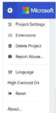
text_image
Microsoft Project Settings Extensions Delete Project Report Abuse... Language High Contrast On Reset About...text_image
1 Select Basic show number 0 show leds 2 Drag A show string Hello! Display led on the screen one character at a time if the string fits on the screen (i.e. is one letter), does not scroll. forever pause (ms) 100 Logic Variables Math Radio Advanced Getting Started 3 Click to Edit A show string Hello Everybody| 1 | Seleccionar |
| 2 | Arrastrar |
| 3 | Hacer clic para editar |
text_image
on start show string "Hello Everybody"flowchart
graph TD
    A["show number"] --> B["forever"]
    B --> C["show number 5"]
    C --> D["0 1 2 3V ON/OFF"]
    D --> E["0 1 2 3V ON/OFF"]
    E --> F["4 ✓ ✓ ✓ ✓"]
    F --> G[1 ✓ ✓ ✓ ✓ ✓ ✓ ✓ ✓ ✓ ✓ ✓ ✓ ✓ ✓ ✓ ✓ ✓ ✓ ✓ ✓ ✓ ✓ ✓ ✓ ✓ ✓ ✓ ✓ ✓ ✓ ✓ ✓ ✓ ✓ ✓ ✓ ✓ ✓ ✓ ✓ ✓ ✓ ✓ ✓ ✓ ✓ ✓ ✓ ✓ ✓ ✓ ✓ ✓ ✓ ✓ ✓ ✓ ✓ ✓ ✓ ✓ ✓ ✓ ✓ ✓ ✓ ✓ ✓ ✓ ✓ ✓ ✓ ✓ ✓ ✓ ✓ ✓ ✓ ✓ ✓ ✓ ✓ ✓ ✓ ✓ ✓ ✓ ✓ ✓ ✓ ✓ ✓ ✓ ✓ ✓ ✓ ✓ ✓ ✓ ✓✓ ✓✓ ✓✓ ✓✓ ✓✓ ✓✓ ✓✓ ✓✓ ✓✓ ✓✓ ✓✓ ✓✓ ✓✓ ✓✓ ✓✓ ✓✓ ✓✓ ✓✓ ✓✓ ✓✓ ✓✓ ✓✓ ✓✓ ✓✓ ✓✓ ✓✓ ✓✓ ✓✓ ✓✓ ✓✓ ✓✓ ✓✓ ✓✓ ✓✓ ✓✓ ✓✓ ✓✓ ✓✓ ✓✓ ✓✓ ✓✓ ✓✓ ✓✓ ✓✓ ✓✓ ✓✓ ✓✓ ✓✓ ✓✓ ✓✓ ✓/✓
text_image
show number 2 pause (ms) 100
text_image
show number 2 pause (ms) 100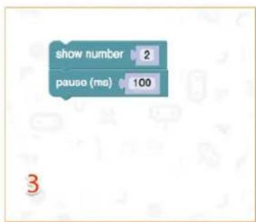
text_image
show number 2 pause (ms) 100 3micro:bit
text_image
Diagram of a breadboard layout with labeled components and wiring, showing circuit connections and component placements.
flowchart
graph TD
    A["on start"] --> B["set pull pin P2 to up"]
    C["forever"] --> D{if digital read pin P2 = 0}
    D -->|Yes| E["digital write pin P0 to 0"]
    D -->|No| F["digital write pin P1 to 1"]
    E --> G["pause (ms) 500"]
    F --> H["pause (ms) 500"]
    G --> I["digital write pin P0 to 1"]
    H --> J["digital write pin P1 to 0"]
text_image
Diagram of a breadboard layout with labeled components and colored indicators for logic or signal processing.Crear el código
text_image
forever plot bar graph of up to analog read pin P0 1023text_image
Diagram of a breadboard layout with labeled components and wiring, showing pin connections and color-coded wires.text_image
on start set CalVal to analog read pin P0 ✓ CalVal item PhoVal Rename variable... Delete the "CalVal" variable on start set CalVal to analog read pin P0text_image
Diagram of an electronic circuit board layout with labeled components and wiring connectionstext_image
on button A pressed digital write pin P0 to 1 digital write pin P1 to 0 digital write pin P2 to 0 on button B pressed digital write pin P0 to 0 digital write pin P1 to 1 digital write pin P2 to 0 on button A+B pressed digital write pin P0 to 0 digital write pin P1 to 0 digital write pin P2 to 1text_image
on button A pressed digital write pin P0 to 1 digital write pin P1 to 0 digital write pin P2 to 0natural_image
Three electronic components: a resistor, a light bulb, and a red LED with pins (no text or symbols)text_image
Diagram of a breadboard layout with labeled components and wiring, including circuit board, indicator lights, and color-coded wires.
text_image
on start set pin P0 ▼ to emit edge ▼ events set pull pin P0 ▼ to up ▼ on event from MICROBIT_ID_IO_P0 ▼ with value MICROBIT_PIN_EVT_FALL ▼ digital write pin P2 ▼ to 1 on event from MICROBIT_ID_IO_P0 ▼ with value MICROBIT_PIN_EVT_RISE ▼ digital write pin P2 ▼ to 0text_image
Diagram of a breadboard layout with labeled components and wiring, showing pin connections and color-coded wires.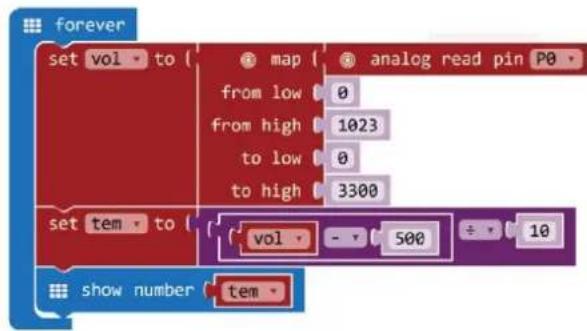
text_image
forever set vol to { map from low 0 from high 1023 to low 0 to high 3300 set tem to { vol - 500 ÷ 10 show number temtext_image
New variable name: CalVal Ok ✓ Cancel ✗text_image
forever set vol to 0text_image
forever set vol to map from low from high to low to high 0 0 1023 0 4text_image
set vol to ( map analog read pin P0 from low 0 from high 1023 to low 0 to high 3300text_image
forever set vol to ( map analog read pin P0 from low 0 from high 1023 to low 0 to high 3300 set vol to 0text_image
set vol to ( map analog read pin P0 from low 0 from high 1023 to low 0 to high 3300text_image
forever set vol to { map { analog read pin P0 from low 0 from high 1023 to low 0 to high 3300 } set vol to 0 ÷ 0text_image
forever set vol to { map from low 0 from high 1023 to low 0 to high 3300 set vol to 0 - 0text_image
forever set vol to { map { analog read pin PO from low 0 from high 1023 to low 0 to high 3300 } set tem to { vol 0 + 0text_image
forever set vol to { map { analog read pin P0 from low 0 from high 1023 to low 0 to high 3300 } set tem to { vol - 500 + 10text_image
forever set vol to { map { analog read pin P0 } from low 0 from high 1023 to low 0 to high 3300 set tem to { vol - 500 + 10 show number 0text_image
forever set vol to { map analog read pin P0 from low 0 from high 1023 to low 0 to high 3300 set tem to { vol - 500 ÷ 10 show number temtext_image
AA Battery 5 AA Battery 1 2 3Vamos a crear un servomotor que gire continuamente dentro de un rango de 0-180°.
natural_image
Three electronic components: a cylindrical capacitor, a rectangular component with pins, and a resistor, all labeled with numbers 4, 5, and 6 (no text or symbols on the components themselves)Vamos a controlar un zumbador.
text_image
Diagram of an electronic circuit board layout with labeled components and wiring connections
flowchart
graph TD
    A["ring tone (Hz)"] --> B["Middle C"]
    C["pause (ms)"] --> D["100"]
    E["ring tone (Hz)"] --> F["Middle E"]
    G["pause (ms)"] --> H["100"]
    I["ring tone (Hz)"] --> J["Middle G"]
    K["pause (ms)"] --> L["100"]
    M["ring tone (Hz)"] --> N["Middle E"]
    O["pause (ms)"] --> P["100"]
text_image
Illustration of seven electronic components with numbered labels beneath each, including a resistor, coiled wire, LED, and T-12 transistor.
text_image
AA Battery 9 AA Battery 1 2 8 3flowchart
graph TD
    A["on start"] --> B["digital write pin P0 to 0"]
    A --> C["set pull pin P1 to up"]
    D["forever"] --> E{if digital read pin P1 = 0}
    E --> F["then digital write pin P0 to 1"]
    E --> G["else digital write pin P0 to 0"]
text_image
Diagram of a breadboard with labeled components and a color palette, showing connections between pins 1, 2, and 3.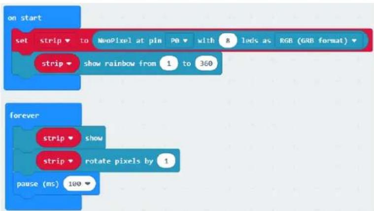
text_image
on start set strip to NeoPixel at pin Pb with 8 leds as RGB (GRB format) strip show rainbow from 1 to 360 forever strip show strip rotate pixels by 1 pause (ms) 100text_image
Add Package... ? 1 neopixel 2 devices BETA - Camera, remote control and other Bluetooth services. App required. bluetooth Bluetooth services neopixel Adafruit NeoPixel drivertext_image
Add Package... ? neopixel neopixel A Neo-Pixel package for pix-microbit bitbot A BitBot package for pix-microbit. BitBot Official Microsoft MakeCode package for the BitBot robot https://4tronix.co.uk/bitbot/text_image
Diagram of a breadboard with labeled components and colored wires, showing connections between pins 1, 2, and 3.
Hands on computing education
Microsoft MakeCode brings computer science to life for all students with fun projects, immediate results, and both block and text editors for learners at different levels.
natural_image
Illustration of a micro-bit integrated circuit chip with gold contacts and red LED indicators (no text or symbols)micro:bit
Start coding with microbit >
natural_image
Circular electronic circuit board with LED indicators and pin labels, set against a blue background (no readable text or symbols)Circuit Playground Express
Start coding with Circuit Playground Express >

natural_image
Pixelated icon of a sitting figure on a green background (no text or symbols)Minecraft
Start coding with Minecraft
text_image
micro:bit Let's Code Ideas Meet micro:bit Teach Buy English- Power your imagination with code Did you know that you can code your BBC micro:bit using Blocks, JavaScript, and Python? If you have never used a BBC micro:bit try our Quick Start Guide. Microsoft micro:bit Programs Show strong Show strong Show strong Show strong Show strong Show strong Show strong Show strong Show strong Show strong Show strong Show strong Show strong Show strong Show strong Show strong Show strong Show strong Show strong Show strong Show strong Show strong Show strong Show strong Show strong Show strong Show strong Show strong Show strong Show strong Show strong Show strong Show strong Show strong (100%) Show strong (100%) Show strong (100%) Show strong (100%) Show strong (100%) Show strong (100%) Show strong (100%) Show strong (100%) Show strong (100%) Show strong (100%) Show strong (100%) Show strong (100%) Show strong (100%) Show strong (80%) Show strong (80%) Show strong (80%) Show strong (80%) Show strong (80%) Show strong (80%) Show strong (80%) Show strong (80%) Show strong (80%) Show strong (80%) Show strong (80%) Show strong (80%) Show strong (80%) Show strong (80%) Show strong (80% List Python Language Logo Translation Search Advances JavaScript Blocks Editor The micro:bit's JavaScript Blocks editor makes it easy to program your BBC micro:bit in Blocks and JavaScript. Powered by MakeCode. If you have any issues accessing the editor, check that it isn't blocked in your school. If you need some inspiration then check out these Projects. Let's Code Reference Lessonstext_image
New Project Import Blocks JavaScript Support Getting started Projects Reference Blocks JavaScript Hardware Buytext_image
Microsoft Project Settings Extensions Delete Project Report Abuse... Language High Contrast On Reset About...text_image
1 Select Basic show number 0 Input Show leds Music Led Loops Logic Variables Math Radio Advanced Getting Started 2 Drag A show string → Hello Everybody A show string → Hello! Dress the line on the display one character at a key. If the string fits on the screen (i.e. is one letter), does not scroll. C forever ○ pause (ms) 100 3 Click to Edit A show string → Hello Everybodytext_image
on start show string "Hello Everybody"text_image
show number 2 pause (ms) 100
text_image
show number 2 pause (ms) 100micro:bit
text_image
Diagram of an electronic circuit board with labeled components and wiring, showing connections between pins and a breadboard layout.
flowchart
graph TD
    A["on start"] --> B["set pull pin P2 to up"]
    C["forever"] --> D{if digital read pin P2}
    D --> E["0"]
    D --> F["then digital write pin P0 to 0"]
    D --> G["0"]
    D --> H["0"]
    D --> I["1"]
    J["pause (ms) 500"] --> K["0"]
    L["digital write pin P0 to 1"] --> M["0"]
    N["digital write pin P1 to 0"] --> O["0"]
    P["pause (ms) 500"] --> Q["0"]
1.
text_image
Diagram of a breadboard layout with labeled components and colored indicators for logic or signal processing.text_image
plot bar graph of up to analog read pin P0 1023Langes Bein = Emitter
Negative Kathode
text_image
Diagram of a breadboard layout with labeled components and wiring, showing pin connections and color-coded wires.text_image
on start set CalVal to analog read pin P0 ✓ CalVal item PhoVal Rename variable... Delete the "CalVal" variable on start set CalVal to analog read pin P0text_image
Diagram of an electronic circuit board layout with labeled components and wiring connectionstext_image
on button A pressed digital write pin P0 to 1 digital write pin P1 to 0 digital write pin P2 to 0 on button B pressed digital write pin P0 to 0 digital write pin P1 to 1 digital write pin P2 to 0 on button A+B pressed digital write pin P0 to 0 digital write pin P1 to 0 digital write pin P2 to 1text_image
on button A pressed digital write pin P0 to 1 digital write pin P1 to 0 digital write pin P2 to 0text_image
Three labeled electronic components: a resistor, a diode, and a light bulb, each marked with a numbered circle.text_image
Diagram of a breadboard layout with labeled components and wiring, including circuit board, indicator lights, and color-coded wires.
text_image
on start set pin P0 ▼ to emit edge ▼ events set pull pin P0 ▼ to up ▼ on event from MICROBIT_ID_IO_P0 ▼ with value MICROBIT_PIN_EVT_FALL ▼ digital write pin P2 ▼ to 1 on event from MICROBIT_ID_IO_P0 ▼ with value MICROBIT_PIN_EVT_RISE ▼ digital write pin P2 ▼ to 0text_image
Diagram of a breadboard layout with labeled components and wiring, showing pin connections and color-coded wires.
text_image
forever set vol to { map from low 0 from high 1023 to low 0 to high 3300 set tem to { vol - 500 ÷ 10 show number temtext_image
forever set vol to 0text_image
forever set vol to map from low from high to low to high 0 0 1023 0 4text_image
set vol to ( map analog read pin P0 from low 0 from high 1023 to low 0 to high 3300text_image
forever set vol to map analog read pin P0 from low 0 from high 1023 to low 0 to high 3300 set vol to 0text_image
set vol to { map from low 0 from high 1023 to low 0 to high 3300 analog read pin P0text_image
forever set vol to { map { analog read pin P0 from low 0 from high 1023 to low 0 to high 3300 } set vol to 0 ÷ 0text_image
forever set vol to ( map ( analog read pin P0 ) from low 0 from high 1023 to low 0 to high 3300 set vol to ( 0 - 0text_image
set vol to map analog read pin P0 from low 0 from high 1023 to low 0 to high 3300 set tem to vol 0 ÷ 0text_image
forever set vol to map analog read pin P0 from low 0 from high 1023 to low 0 to high 3300 set tem to vol - 500 + 10text_image
forever set vol to { map { analog read pin P0 from low 0 from high 1023 to low 0 to high 3300 } set tem to { vol - 500 ÷ 10 } show number 0text_image
forever set vol to { map { analog read pin P0 from low 0 from high 1023 to low 0 to high 3300 } } set tem to { vol - 500 + 10 } show number temnatural_image
3D illustration of a SERVO-branded mechanical device with no visible text or symbols on its body, labeled '4' below (no readable text or symbols on the device itself)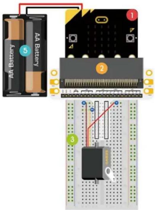
text_image
AA Battery 5 AA Battery 1 2 3natural_image
Three electronic components: a cylindrical capacitor, a potentiometer, and a resistor, each labeled with a number (4, 5, 6) in purple, blue, and pink circles respectively.text_image
Diagram of an electronic circuit board with labeled components and wiring, including a breadboard layout and a transistor block.flowchart
graph TD
    A["ring tone (Hz)"] --> B[" Middle C "]
    C["pause (ms)"] --> D[" 100 "]
    E["ring tone (Hz)"] --> F[" Middle E "]
    G["pause (ms)"] --> H[" 100 "]
    I["ring tone (Hz)"] --> J[" Middle G "]
    K["pause (ms)"] --> L[" 100 "]
    M["ring tone (Hz)"] --> N[" Middle E "]
    O["pause (ms)"] --> P[" 100 "]
text_image
Diagram showing seven electronic components with numbered labels: resistor, inductor, LED, and T-12 transistor.
text_image
AA Battery 9 1 2 3 8flowchart
graph TD
    A["on start"] --> B["digital write pin P0 to 0"]
    A --> C["set pull pin P1 to up"]
    D["forever"] --> E{if digital read pin P1 = 0}
    E --> F["then digital write pin P0 to 1"]
    E --> G["else digital write pin P0 to 0"]
text_image
Diagram of a breadboard with labeled components and a color palette, showing pin connections and wiring paths.text_image
on start set strip to NeoPixel at pin PB with 8 leds as RGB (GRB format) strip show rainbow from 1 to 360 forever strip show strip rotate pixels by 1 pause (ms) 100text_image
Add Package... 1 neopixel 2 devices BETA - Camera, remote control and other Bluetooth services. App required. bluetooth Bluetooth services neopixel Adafruit NeoPixel drivertext_image
Diagram of a breadboard with labeled components and colored wires, showing connections between pins 1, 2, and 3.
Hands on computing education
Microsoft MakeCode brings computer science to life for all students with fun projects, immediate results, and both block and text editions for learners at different levels.
natural_image
Illustration of a micro-bit microphone with circuit board and pin symbols (no readable text or labels)micro:bit
Start coding with microbit

natural_image
Circular electronic circuit board with labeled pins and components, set against a blue background (no readable text or symbols)Circuit Playground Express
Start coding with Circuit Playground Express

natural_image
Pixelated white icon of a person sitting on a bench against a green background (no text or symbols)Minecraft
Start coding with Minecraft >
text_image
micro:bit Let's Code Ideas Meet micro:bit Teach Buy English- Power your imagination with code Did you know that you can code your BBC micro:bit using Blocks, JavaScript, and Python? If you have never used a BBC micro:bit try our Quick Start Guide. micro:bit Programs Microsoft Microsoft JavaScript Blocks Editor The micro:bit's JavaScript Blocks editor makes it easy to program your BBC micro:bit in Blocks and JavaScript. Powered by MakeCode. If you have any issues accessing the editor, check that it isn't blocked in your school. If you need some inspiration then check out these Projects. Let's Code Reference Lessonstext_image
New Project Import Blocks JavaScript Support Getting started Projects Reference Blocks JavaScript Hardware Buy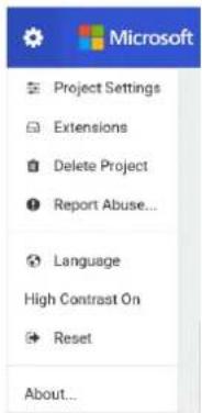
text_image
Microsoft Project Settings Extensions Delete Project Report Abuse... Language High Contrast On Reset About...text_image
1 Select Basic show number 0 Input show leds Music Led Loops Logic Variables Math Radio Advanced Getting Started 2 Drag A show string Hello Everybody A show string Hello! Display text on the screen one completely as a time if the string fits on the screen (i.e. is one letter), does not sort. C forever pause (ms) 100 3 Click to Edittext_image
on start show string "Hello Everybody"flowchart
graph TD
    A["show number 2"] --> B["pause (ms) 100"]
    style A fill:#4CAF50,stroke:#388E3C
    style B fill:#4CAF50,stroke:#388E3C
flowchart
graph TD
    A["show number"] -->|2| B["pause (ms)"]
    B -->|100| C["End"]

text_image
show number 2 pause (ms) 100Testowanie na micro:bit
flowchart
graph TD
    A[" forever "] --> B[" digital write pin P0 to 0 "]
    A --> C[" digital write pin P1 to 1 "]
    A --> D[" pause (ms) 500 "]
    A --> E[" digital write pin P0 to 1 "]
    A --> F[" digital write pin P1 to 0 "]
    A --> G[" pause (ms) 500 "]
text_image
Diagram of an electronic circuit board with labeled components and a corresponding schematic diagram showing connections and wiring.
flowchart
graph TD
    A["on start"] --> B["set pull pin P2 to up"]
    C["forever"] --> D{if digital read pin P2}
    D -->|Yes| E["0"]
    D -->|No| F["1"]
    G["then"] --> H["digital write pin P0 to 0"]
    G --> I["digital write pin P1 to 1"]
    J["pause (ms) 500"] --> K["0"]
    J --> L["1"]
    M[" Digital write pin P0 to 1 "] --> N["0"]
    O[" Digital write pin P1 to 0"] --> P["1"]
    Q[" pause (ms) 500"] --> R["0"]
1.
text_image
Diagram of a breadboard layout with labeled components and colored wires, showing connections to a circuit board.text_image
forever plot bar graph of up to analog read pin P0 1023text_image
Diagram of a breadboard layout with labeled components and wiring, showing pin connections and color-coded wires.text_image
on start set CalVal to analog read pin P0 ✓ CalVal item PhoVal Rename variable... Delete the "CalVal" variable on start set CalVal to analog read pin P0text_image
on start set CalVal to analog read pin P0text_image
Diagram of an electronic circuit board with labeled components and wiring connectionstext_image
on button A - pressed digital write pin P0 to 1 digital write pin P1 to 0 digital write pin P2 to 0 on button B - pressed digital write pin P0 to 0 digital write pin P1 to 1 digital write pin P2 to 0 on button A+B - pressed digital write pin P0 to 0 digital write pin P1 to 0 digital write pin P2 to 1text_image
on button A pressed digital write pin P0 to 1 digital write pin P1 to 0 digital write pin P2 to 0text_image
Three labeled electronic components: a resistor, a diode, and a light bulb, each marked with a numbered circle.text_image
Diagram of an electronic circuit board with labeled components and wiring connections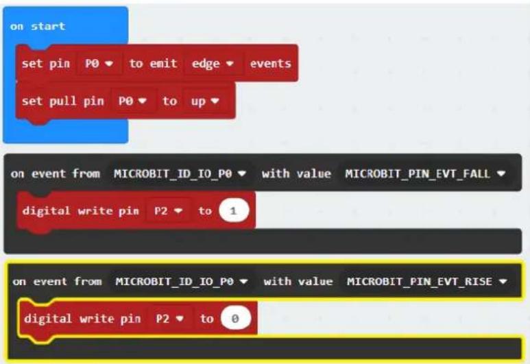
text_image
on start set pin P0 ▼ to emit edge ▼ events set pull pin P0 ▼ to up ▼ on event from MICROBIT_ID_IO_P0 ▼ with value MICROBIT_PIN_EVT_FALL ▼ digital write pin P2 ▼ to 1 on event from MICROBIT_ID_IO_P0 ▼ with value MICROBIT_PIN_EVT_RISE ▼ digital write pin P2 ▼ to 0text_image
Diagram of an electronic circuit board with labeled components and a color-coded lamp panel showing connections to a breadboard.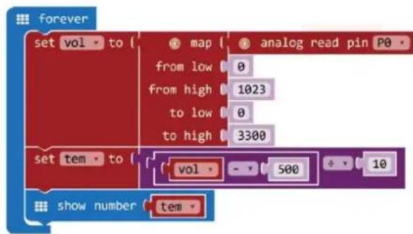
text_image
forever set vol to { map from low 0 from high 1023 to low 0 to high 3300 set tem to { vol - 500 + 10 show number temtext_image
forever set vol to 0text_image
forever set vol to map from low from high to low to high 0 0 1023 0 4text_image
forever set vol to ( map from low 0 from high 1023 to low 0 to high 3300 analog read pin P0text_image
forever set vol to { map analog read pin P0 from low 0 from high 1023 to low 0 to high 3300 set vol to 0text_image
set vol to { map from low 0 from high 1023 to low 0 to high 3300 analog read pin P0text_image
forever set vol to ( map ( analog read pin P0 ) from low 0 from high 1023 to low 0 to high 3300 set vol to 0 ÷ 0text_image
forever set vol to ( map ( analog read pin P0 ) from low 0 from high 1023 to low 0 to high 3300 set vol to ( 0 - 0text_image
set vol to { map from low 0 from high 1023 to low 0 to high 3300 set tem to { vol 0 ÷ 0 analog read pin P0text_image
forever set vol to map analog read pin P0 from low 0 from high 1023 to low 0 to high 3300 set tem to vol - 500 + 10text_image
forever set vol to map analog read pin P0 from low 0 from high 1023 to low 0 to high 3300 set tem to vol - 500 + 10 show number 0text_image
forever set vol to { map analog read pin P0 from low 0 from high 1023 to low 0 to high 3300 set tem to { vol - 500 ÷ 10 show number temnatural_image
Illustration of a SERVO-branded electrical component with three wires and a pin, labeled '4' below (no text or symbols on the device itself)
text_image
AA Battery 5 AA Battery 1 2 3natural_image
Three electronic components: a cylindrical capacitor, a rectangular component with pins, and a resistor, all labeled with numbers 4, 5, and 6 (no text or symbols on the components themselves)text_image
Diagram of an electronic circuit board layout with labeled components and wiring connections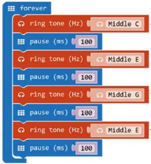
flowchart
graph TD
    A["ring tone (Hz)"] --> B["Middle C"]
    C["pause (ms)"] --> D["100"]
    E["ring tone (Hz)"] --> F["Middle E"]
    G["pause (ms)"] --> H["100"]
    I["ring tone (Hz)"] --> J["Middle G"]
    K["pause (ms)"] --> L["100"]
    M["ring tone (Hz)"] --> N["Middle E"]
    O["pause (ms)"] --> P["100"]
1.
text_image
AA Battery 9 1 2 3 8flowchart
graph TD
    A["on start"] --> B["digital write pin P0 to 0"]
    A --> C["set pull pin P1 to up"]
    D["forever"] --> E{if digital read pin P1 = 0}
    E --> F["then digital write pin P0 to 1"]
    E --> G["else digital write pin P0 to 0"]
text_image
Diagram of a breadboard with labeled components and a color palette, showing connections between pins and a circuit board.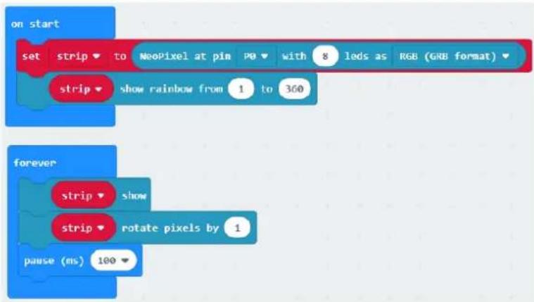
text_image
on start set strip to NeoPixel at pin P0 with 8 leds as RGB (GRB format) strip show rainbow from 1 to 360 forever strip show strip rotate pixels by 1 pause (ms) 100text_image
Add Package... 1 neopixel 2 devices BETA - Camera, remote control and other Bluetooth services. App required. Bluetooth Bluetooth services neopixel AdaFruit NeoPixel drivertext_image
on start set strip to NeoPixel at pin P0 with 8 leds as RGB (GRB format)text_image
Diagram of a breadboard with labeled components and colored wires, showing connections to a circuit board.
Hands on computing education
Microsoft MakeCode brings computer science to life for all students with fun projects, immediate results, and both block and text editions for learners at different levels.

natural_image
Illustration of a micro-credit card with circuit board and pin symbols (no readable text or labels)micro:bit
Start coding with microorbit >
natural_image
Circular electronic circuit board with colored pins on a blue background (no readable text or symbols)Circuit Playground Express
Start coding with Circuit Playground Express

natural_image
Pixelated white icon of a person sitting on a bench against a green background (no text or symbols)Minecraft
Start coding with Minecraft >
text_image
micro:bit Let's Code Ideas Meet micro:bit Teach Buy English- Power your imagination with code Did you know that you can code your BBC micro:bit using Blocks, JavaScript, and Python? If you have never used a BBC micro:bit try our Quick Start Guide. micro:bit Programs Microsoft Microsoft JavaScript Blocks Editor The micro:bit's JavaScript Blocks editor makes it easy to program your BBC micro:bit in Blocks and JavaScript. Powered by MakeCode. If you have any issues accessing the editor, check that it isn't blocked in your school. If you need some inspiration then check out these Projects. Let's Code Reference Lessonstext_image
New Project Import Blocks JavaScript Support Getting started Projects Reference Blocks JavaScript Hardware Buy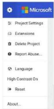
text_image
Microsoft Project Settings Extensions Delete Project Report Abuse... Language High Contrast On Reset About...text_image
1 Select Basic show number 0 Input show leds Music Led Loops Logic Variables Math Radio Advanced Getting Started 2 Drag A show string Hello Everybody A show string Hello! Display text on the screen one completely as a time if the string fits on the screen (i.e. is one letter), does not sort. C forever pause (ms) 100 3 Click to Edit1 Selecionar
2 Arrastar
text_image
on start show string "Hello Everybody"flowchart
graph TD
    A["show number 0"] --> B["forever"]
    B --> C["show number 5"]
    C --> D["0 1 2 3V OND"]
    D --> E["show leds 0 1 2 3 4"]
    E --> F["0 ✓ ✓ ✓ ✓ ✓ ✓ ✓ ✓ ✓ ✓ ✓ ✓ ✓ ✓ ✓ ✓ ✓ ✓ ✓ ✓ ✓ ✓ ✓ ✓ ✓ ✓ ✓ ✓ ✓ ✓ ✓ ✓ ✓ ✓ ✓ ✓ ✓ ✓ ✓ ✓ ✓ ✓ ✓ ✓ ✓ ✓ ✓ ✓ ✓ ✓ ✓ ✓ ✓ ✓ ✓ ✓ ✓ ✓ ✓ ✓ ✓ ✓ ✓ ✓ ✓ ✓ ✓ ✓ ✓ ✓ ✓ ✓ ✓ ✓ ✓ ✓ ✓ ✓ ✓ ✓ ✓ ✓ ✓ ✓ ✓ ✓ ✓ ✓ ✓ ✓ ✓ ✓ ✓ ✓ ✓ ✓ ✓ ✓ ✓ ✓✓"]
text_image
show number 2 pause (ms) 100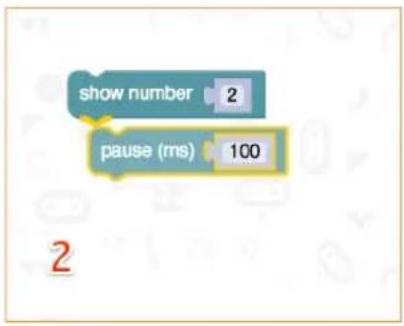
text_image
show number 2 pause (ms) 100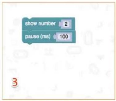
text_image
show number 2 pause (ms) 100Testar no micro:bit
flowchart
graph TD
    A[" forever"] --> B[" digital write pin P0 to 0 "]
    A --> C[" digital write pin P1 to 1 "]
    A --> D[" pause (ms) 500 "]
    A --> E[" digital write pin P0 to 1 "]
    A --> F[" digital write pin P1 to 0 "]
    A --> G[" pause (ms) 500 "]
text_image
Diagram of a breadboard layout with labeled components and colored wires, showing pin connections and color-coded indicators.
flowchart
graph TD
    A["on start"] --> B["set pull pin P2 to up"]
    C["forever"] --> D{if ( digital read pin P2 = 0
then
digital write pin P0 to 0
digital write pin P1 to 1
pause (ms) 500
digital write pin P0 to 1
digital write pin P1 to 0
pause (ms) 500 }}
1.
text_image
Diagram of a breadboard layout with labeled components and colored indicators for voltage and current measurement.text_image
forever plot bar graph of up to analog read pin P0 1023text_image
Diagram of a breadboard layout with labeled components and wiring, showing pin connections and color-coded wires.text_image
on start set CalVal to analog read pin P0 ✓ CalVal item PhoVal Rename variable... Delete the "CalVal" variable on start set CalVal to analog read pin P0- Seleccione a variável CalVal e configure o analog read pin para P0.

text_image
on start set CalVal to analog read pin P0text_image
Diagram of an electronic circuit board layout with labeled components and wiring connectionstext_image
on button A - pressed digital write pin P0 to 1 digital write pin P1 to 0 digital write pin P2 to 0 on button B - pressed digital write pin P0 to 0 digital write pin P1 to 1 digital write pin P2 to 0 on button A+B - pressed digital write pin P0 to 0 digital write pin P1 to 0 digital write pin P2 to 1Arraste 3 blocos digital write pin P0 to 0 i insira-os no bloco on button A pressed.
text_image
on button A pressed digital write pin P0 to 1 digital write pin P1 to 0 digital write pin P2 to 0text_image
Three labeled electronic components: a resistor, a light bulb, and a red LED with three numbered pins.text_image
Diagram of a breadboard layout with labeled components and wiring, including circuit board, indicator lights, and color-coded wires.
text_image
on start set pin P0 ▼ to emit edge ▼ events set pull pin P0 ▼ to up ▼ on event from MICROBIT_ID_IO_P0 ▼ with value MICROBIT_PIN_EVT_FALL ▼ digital write pin P2 ▼ to 1 on event from MICROBIT_ID_IO_P0 ▼ with value MICROBIT_PIN_EVT_RISE ▼ digital write pin P2 ▼ to 0text_image
Diagram of a breadboard layout with labeled components and wiring, showing connections to a circuit board with pin labels.text_image
forever set vol to { map from low 0 from high 1023 to low 0 to high 3300 set tem to { vol - 500 ÷ 10 show number tem -text_image
forever set vol to map from low from high to low to high 0 0 1023 0 4text_image
set vol to { map from low 0 from high 1023 to low 0 to high 3300 analog read pin P0text_image
forever set vol to ( map ( analog read pin P0 ) from low 0 from high 1023 to low 0 to high 3300 set vol to 0text_image
set vol to map from low 0 from high 1023 to low 0 to high 3300 analog read pin P0text_image
forever set vol to map analog read pin P0 from low 0 from high 1023 to low 0 to high 3300 set vol to 0 + 0text_image
forever set vol to ( map ( analog read pin P0 ) from low 0 from high 1023 to low 0 to high 3300 set vol to ( 0 - - 0text_image
forever set vol to { map { analog read pin P0 from low 0 from high 1023 to low 0 to high 3300 } set tem to vol 0 ÷ 0Defina o valor 0 de mathematical function minus para 500. Do mesmo modo, defina o valor de mathematical function divide para 10
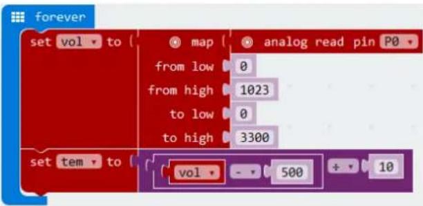
text_image
set vol to { map analog read pin P0 from low 0 from high 1023 to low 0 to high 3300 set tem to { vol - 500 + 10text_image
forever set vol to { map analog read pin P0 from low 0 from high 1023 to low 0 to high 3300 set tem to vol - 500 ÷ 10 show number 0text_image
forever set vol to { map from low 0 from high 1023 to low 0 to high 3300 set tem to vol - 500 + 10 show number temtext_image
AA Battery 5 AA Battery 1 2 3natural_image
Three electronic components: a cylindrical capacitor, a rectangular component with pins, and a segmented resistor, all labeled with numbers 4, 5, and 6 (no text or symbols on the components themselves)text_image
Diagram of an electronic circuit board layout with labeled components and wiring connectionstext_image
AA Battery 9 1 2 3 8flowchart
graph TD
    A["on start"] --> B["digital write pin P0 to 0"]
    A --> C["set pull pin P1 to up"]
    D["forever"] --> E{if digital read pin P1 = 0}
    E --> F["then digital write pin P0 to 1"]
    E --> G["else digital write pin P0 to 0"]
text_image
Diagram of a breadboard layout with labeled components and a color palette, showing pin connections and wiring.text_image
on start set strip to NeoPixel at pin PO with 8 leds as RGB (GRB format) strip show rainbow from 1 to 360 forever strip show strip rotate pixels by 1 pause (ms) 100text_image
neopixel devices BETA - Camera, remote control and other Bluetooth services. App required. bele bluetooth Bluetooth services neopixel AdaFruit NeoPixel drivertext_image
neopixel neopixel A Neo-Pixel package for pwt-microbit bitbot A BitBot package for pwt-microbit. BitBot Official Microsoft MakerCode package for the Bit Bot robot https://4tronix.co.uk/bitbot/Pode encontrar os blocos NeoPixel at pin P0 with 24 leds, item show rainbow from 1 to 360, item show e items rotate pixels by 1 em NeoPixel no Code Drawer.
- Arraste e largue o bloco set strip to NeoPixel noP0 com 24 leds RGB (formato GRB) no bloco on start. Ajuste o pino para P0 e o valor de 24 a 8 (temos 8 LEDs no anel LED).
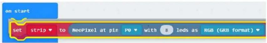
text_image
on start set strip to NeoPixel at pin P0 with 8 leds as RGB (GRB format)text_image
on start set strip to NeoPixel at pin PO with 8 leds as RGB (GRB format) strip show rainbow from 1 to 360Velleman® Service and Quality Warranty
Since its foundation in 1972, Velleman® acquired extensive experience in the electronics world and currently distributes its products in over 85 countries. All our products fulfil strict quality requirements and legal stipulations in the EU. In order to ensure the quality, our products regularly go through an extra quality check, both by an internal quality department and by specialized external organisations. If, all precautionary measures notwithstanding, problems should occur, please make appeal to our warranty (see guarantee conditions).
General Warranty Conditions Concerning Consumer Products (for EU):
- All consumer products are subject to a 24-month warranty on production flaws and defective material as from the original date of purchase.
- Velleman® can decide to replace an article with an equivalent article, or to refund the retail value totally or partially when the complaint is valid and a free repair or replacement of the article is impossible, or if the expenses are out of proportion.
You will be delivered a replacing article or a refund at the value of 100% of the purchase price in case of a flaw occurred in the first year after the date of purchase and delivery, or a replacing article at 50% of the purchase price or a refund at the value of 50% of the retail value in case of a flaw occurred in the second year after the date of purchase and delivery.
• Not covered by warranty:
- all direct or indirect damage caused after delivery to the article (e.g. by oxidation, shocks, falls, dust, dirt, humidity...), and by the article, as well as its contents (e.g. data loss), compensation for loss of profits;
- consumable goods, parts or accessories that are subject to an aging process during normal use, such as batteries (rechargeable, non-rechargeable, built-in or replaceable), lamps, rubber parts, drive belts... (unlimited list);
- flaws resulting from fire, water damage, lightning, accident, natural disaster, etc....;
- flaws caused deliberately, negligently or resulting from improper handling, negligent maintenance, abusive use or use contrary to the manufacturer's instructions;
- damage caused by a commercial, professional or collective use of the article (the warranty validity will be reduced to six (6) months when the article is used professionally);
- damage resulting from an inappropriate packing and shipping of the article; - all damage caused by modification, repair or alteration performed by a third party without written permission by Velleman®.
- Articles to be repaired must be delivered to your Velleman® dealer, solidly packed (preferably in the original packaging), and be completed with the original receipt of purchase and a clear flaw description.
- Hint: In order to save on cost and time, please reread the manual and check if the flaw is caused by obvious causes prior to presenting the article for repair. Note that returning a non-defective article can also involve handling costs.
• Repairs occurring after warranty expiration are subject to shipping costs.
- The above conditions are without prejudice to all commercial warranties.
The above enumeration is subject to modification according to the article (see article's manual).