6906506 - Saw table WOLFCRAFT - Free user manual and instructions
Find the device manual for free 6906506 WOLFCRAFT in PDF.
User questions about 6906506 WOLFCRAFT
0 question about this device. Answer the ones you know or ask your own.
Ask a new question about this device
Download the instructions for your Saw table in PDF format for free! Find your manual 6906506 - WOLFCRAFT and take your electronic device back in hand. On this page are published all the documents necessary for the use of your device. 6906506 by WOLFCRAFT.
USER MANUAL 6906506 WOLFCRAFT
text_image
wolfcraft®CE

text_image
TÜVRhenland® CERTIFIED GS geprüfte Sicherheit www.tux.com ID 0000039236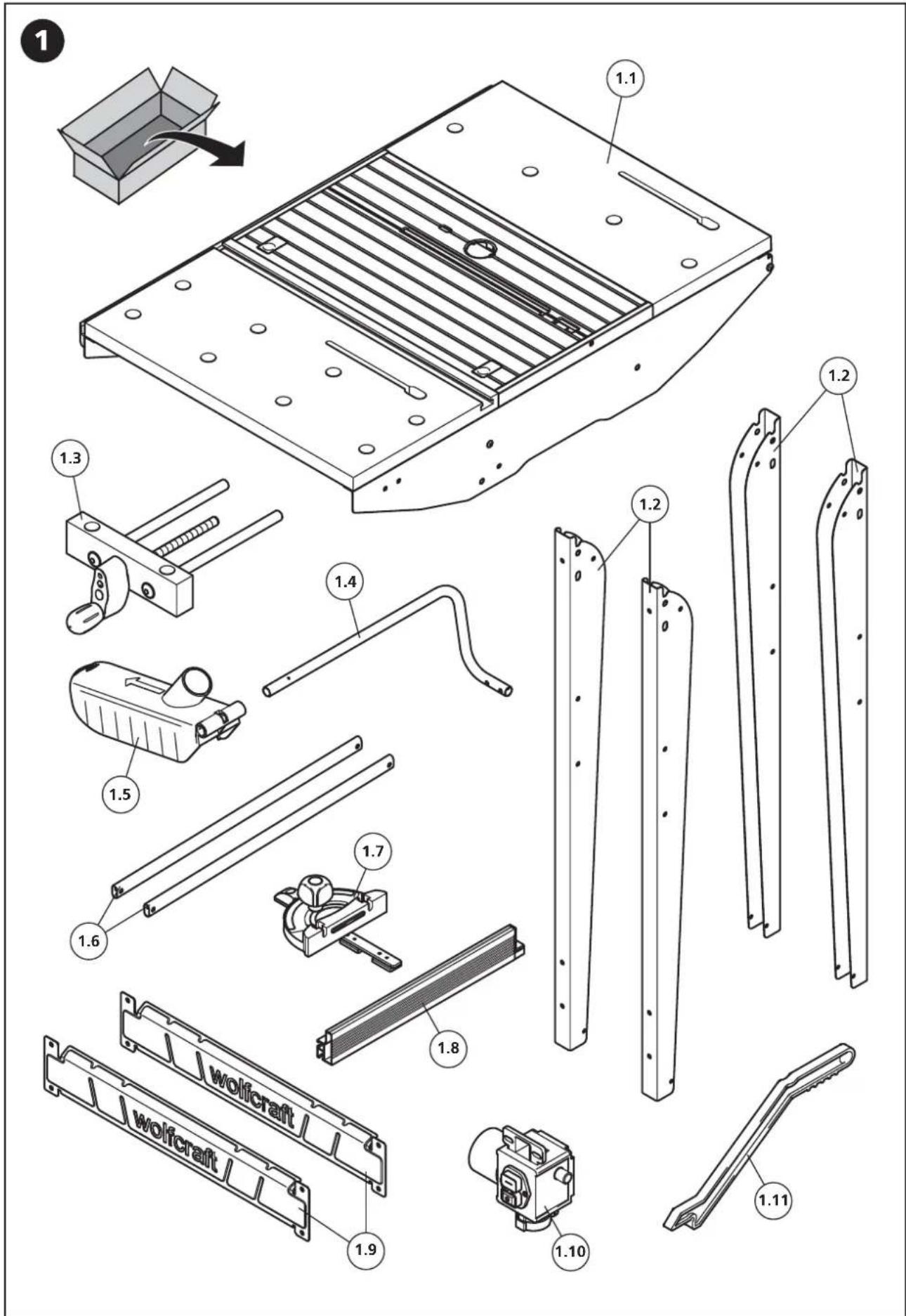
text_image
Technical diagram of a wolfcraft assembly with numbered parts for identification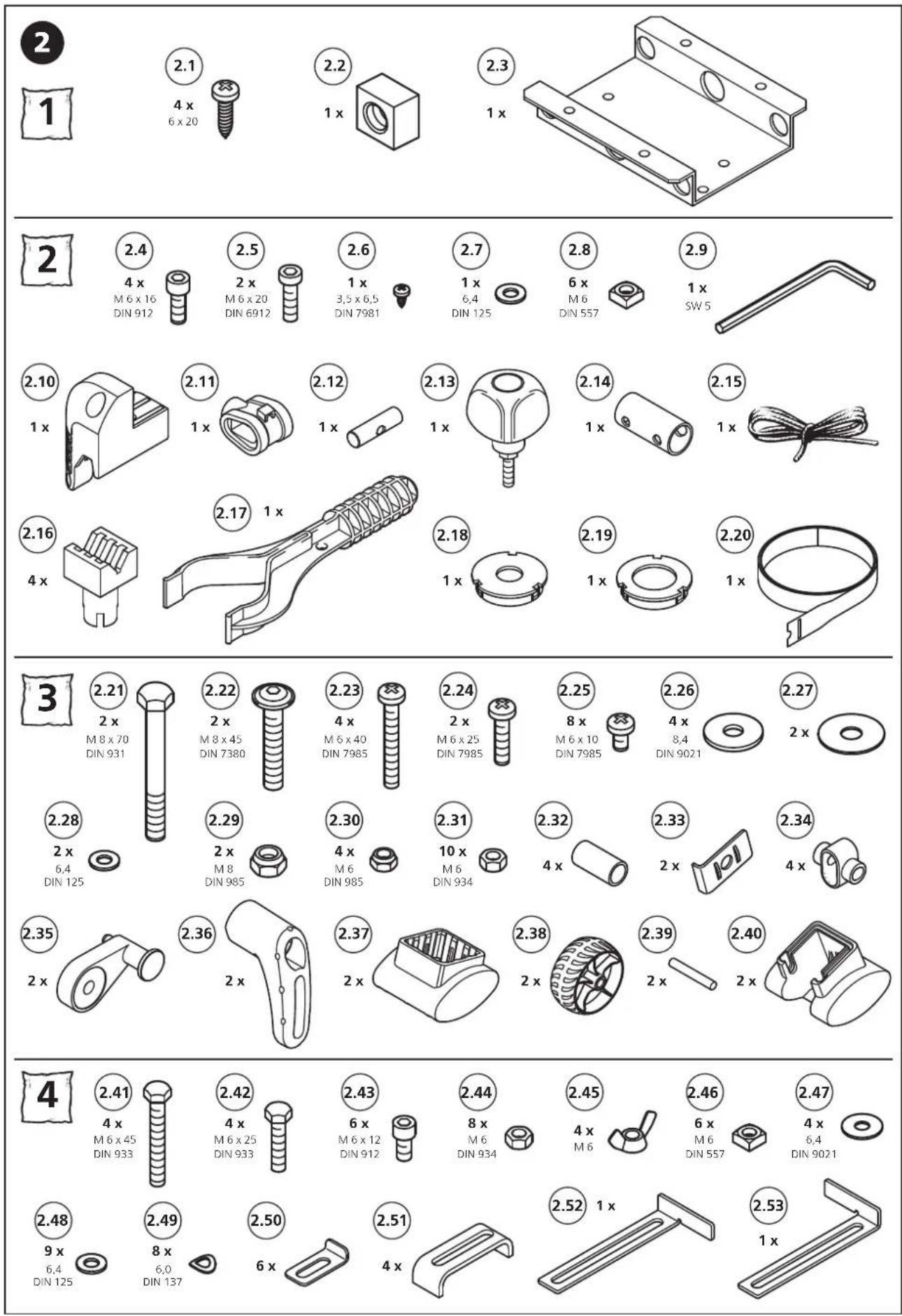
other
| Item | Size (x) | Material Type | DIN | |---|---|---|---| | 1 | 2.1 | 4 x 6 x 20 | 6 x 20 | | 2 | 2.2 | 1 x | 1 x | | 3 | 2.4 | 4 x M 6 x 16 DIN 912 | 6 x 16 | | 4 | 2.5 | 2 x M 6 x 20 DIN 6912 | 6 x 20 | | 5 | 2.6 | 1 x 3,5 x 6,5 DIN 7981 | 7 x 6,5 | | 6 | 2.7 | 1 x 6,4 DIN 125 | 6,4 | | 7 | 2.8 | 6 x M 6 DIN 557 | 557 | | 8 | 2.9 | 1 x SW 5 | - | | 9 | 2.10 | 1 x | - | | 10 | 2.11 | 1 x | - | | 11 | 2.12 | 1 x | - | | 12 | 2.13 | 1 x | - | | 13 | 2.14 | 1 x | - | | 14 | 2.15 | 1 x | - | | 15 | 2.16 | - | - | | 16 | 2.17 | 1 x | - | | 17 | 2.18 | 1 x | - | | 18 | 2.19 | 1 x | - | | 19 | 2.20 | - | - | | 20 | - | - | - | | 21 | - | - | - | | 22 | - | - | - | | 23 | - | - | - | | 24 | - | - | - | | 25 | - | - | - | | 26 | - | - | - | | 27 | - | - | - | | 28 | - | - | - | | 29 | - | - | - | | 30 | - | - | - | | 31 | - | - | - | | 32 | - | - | - | | 33 | - | - | - | | 34 | - | - | - | | 35 | - | - | - | | 36 | - | - | - | | 37 | - | - | - | | 38 | - | - | - | | 39 | - | - | - | | 40 | - | - | - | | 41 | - | - | - | | 42 | - | - | - | | 43 | - | - | - | | 44 | - | - | - | | 45 | - | - | - | | 46 | - | - | - | | 47 | - | - | - | | 48 | - | - | - | | 49 | - | - | - | | 50 | - | - | - | | 51 | - | - | - | | 52 | - | - | - | | 53 | - | - | - | The image contains multiple charts with labels for items and sizes. The charts are grouped in rows and columns based on the number of items (e.g., '4' is repeated twice). Each chart displays a separate label with its corresponding size and a numerical value below it.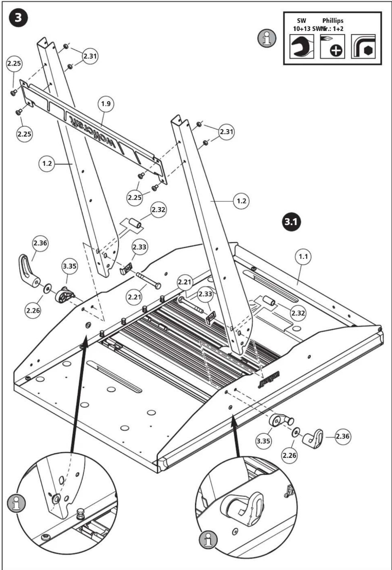
text_image
SW Phillips 10+13 SWNR.: 1+2 2.25 2.31 1.9 2.25 1.2 2.25 2.32 2.36 2.33 2.35 2.21 2.21 2.33 2.32 2.26 3.35 3.36 2.26 2.36 1.1 SWNR.: 1+2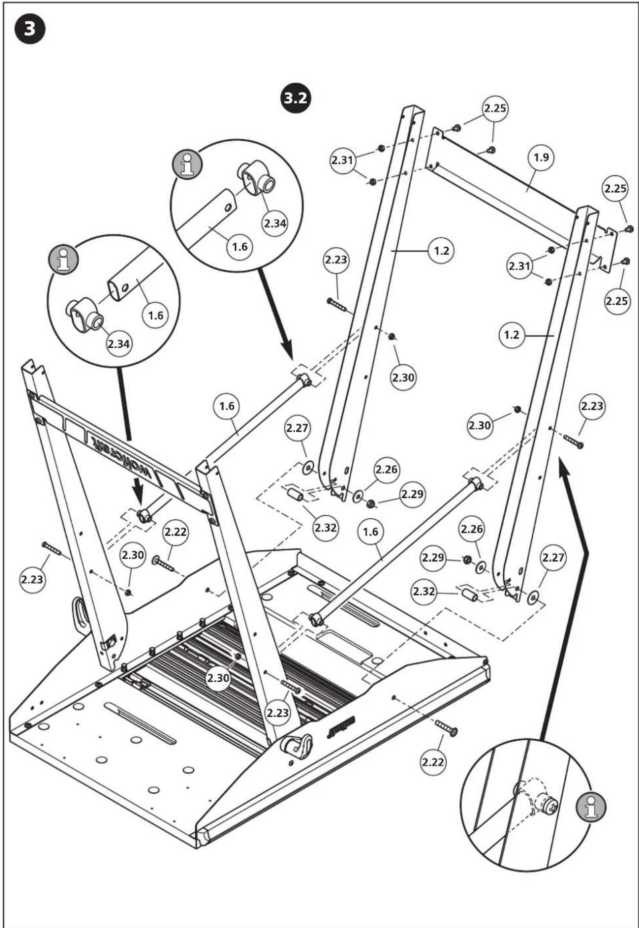
text_image
3 3.2 2.25 2.31 1.9 2.25 2.34 1.6 2.23 1.2 2.31 2.25 2.34 1.6 2.30 2.30 2.27 2.30 2.23 2.26 2.29 2.32 1.6 2.26 2.29 2.32 2.27 2.23 2.30 2.30 2.23 2.30 2.23 2.30 2.23 2.30 2.23 2.22 2.22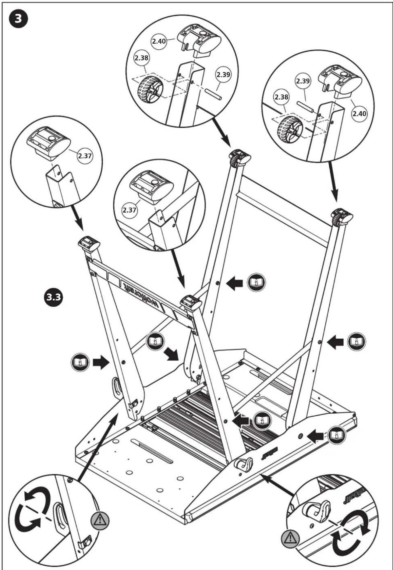
text_image
3 2.40 2.38 2.39 2.38 2.39 2.40 2.37 2.37 3.3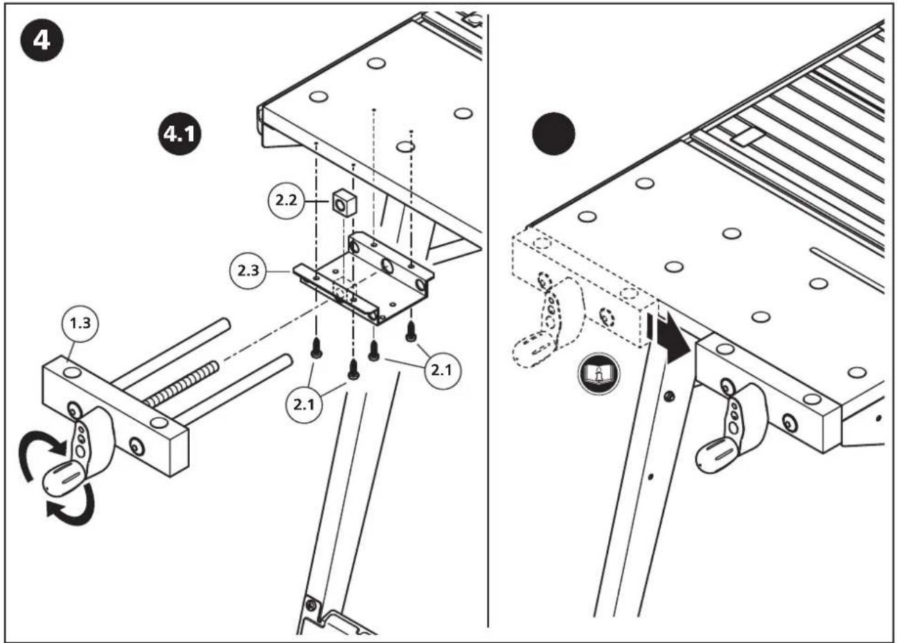
text_image
4 4.1 2.2 2.3 2.1 2.1 1.3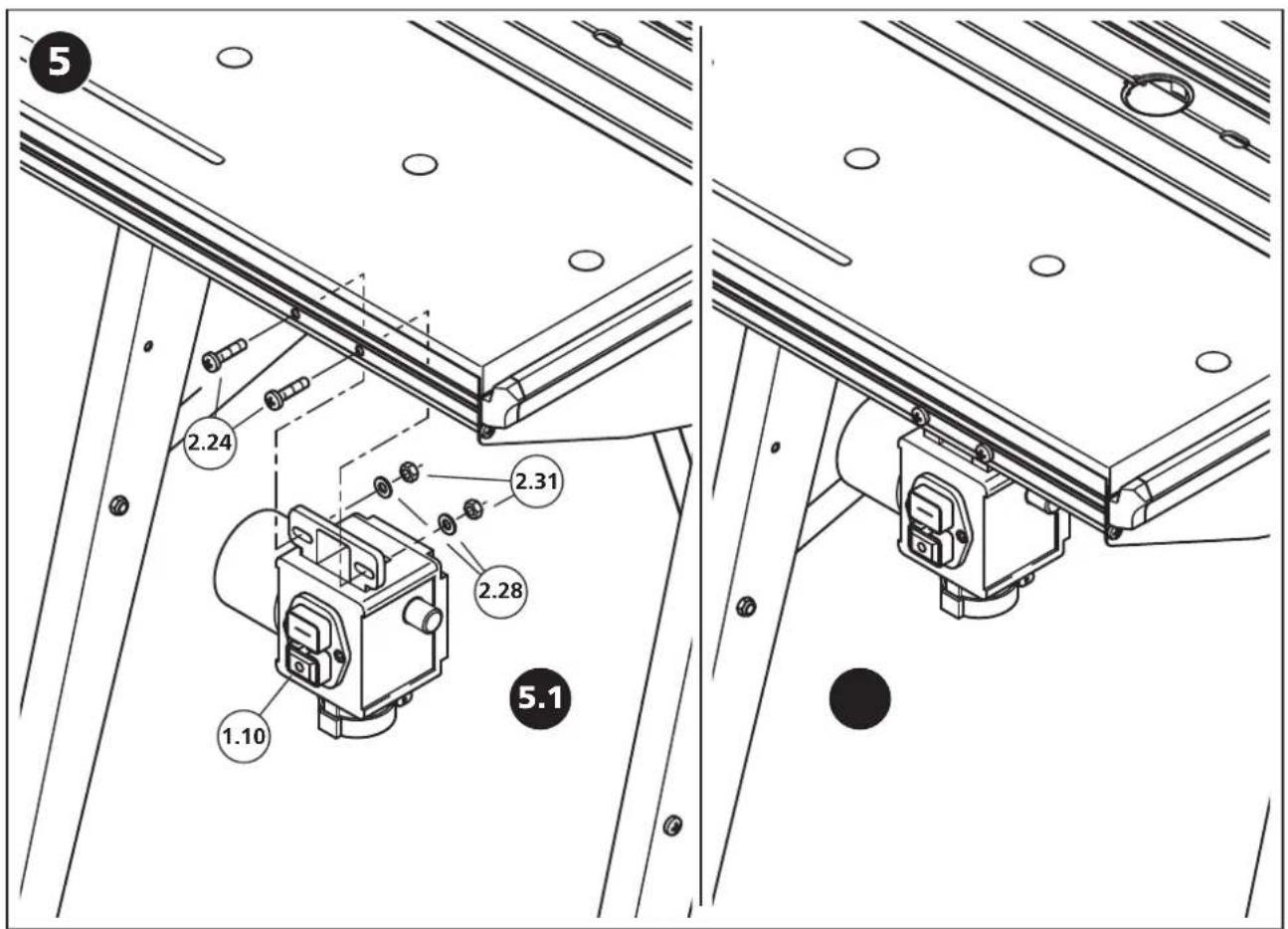
text_image
5 2.24 2.31 2.28 1.10 5.1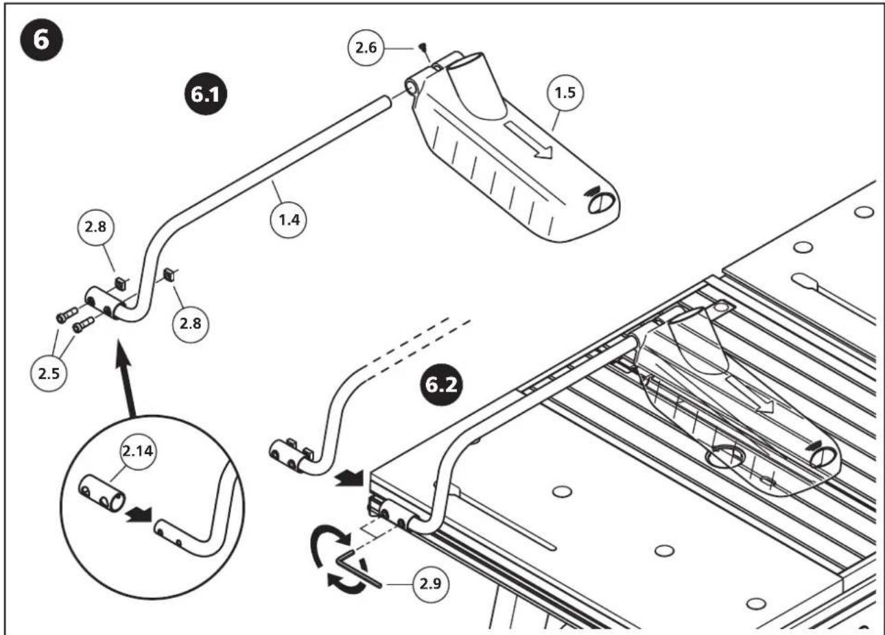
text_image
6 2.6 1.5 6.1 2.8 2.8 2.5 1.4 6.2 2.14 2.9
text_image
7 2.15 2.17 8 1.11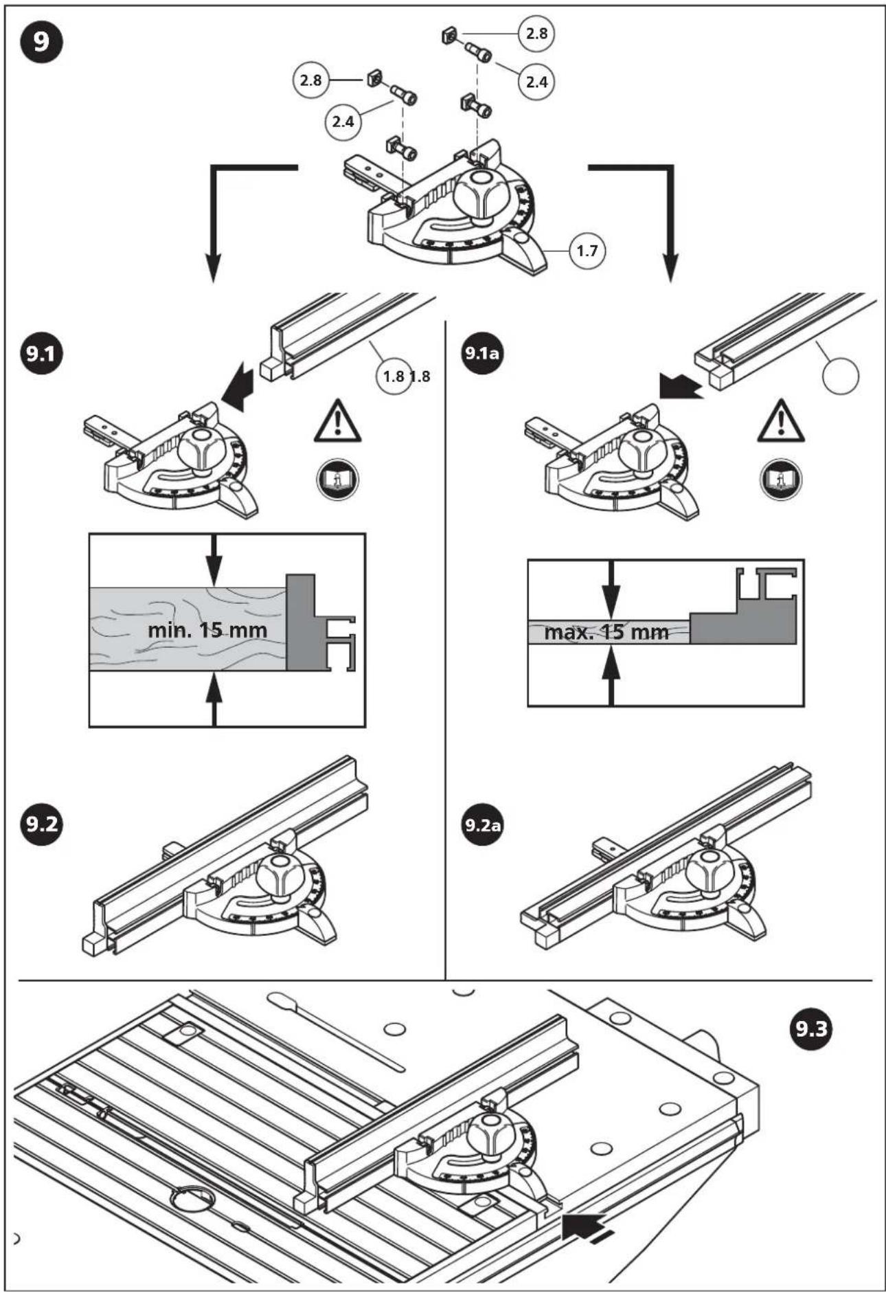
text_image
10 2.12 2.10 2.7 2.11 2.13 10.1 2.8 2.4 1.8 10.4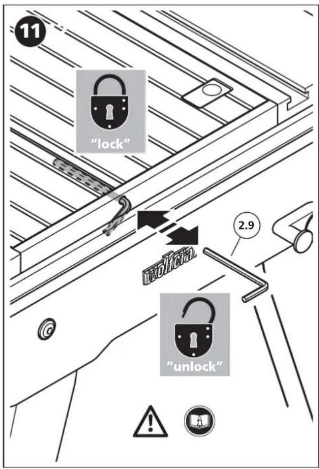
text_image
"lock" 2.9 "unlock"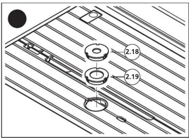
text_image
2.18 2.19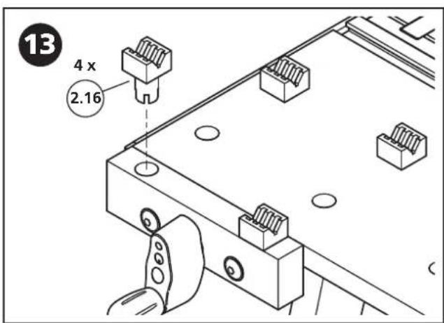
text_image
13 4 x 2.16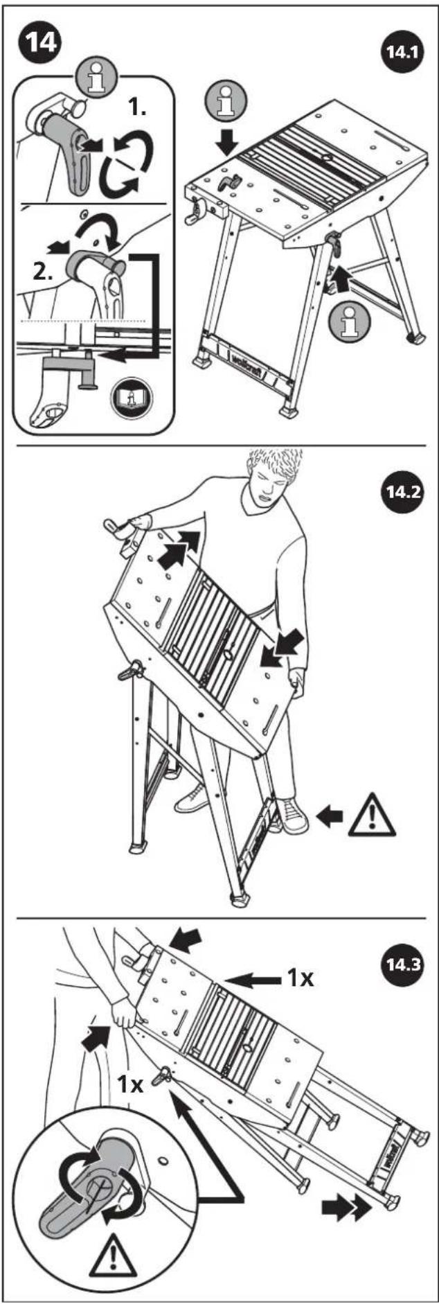

text_image
15 15.1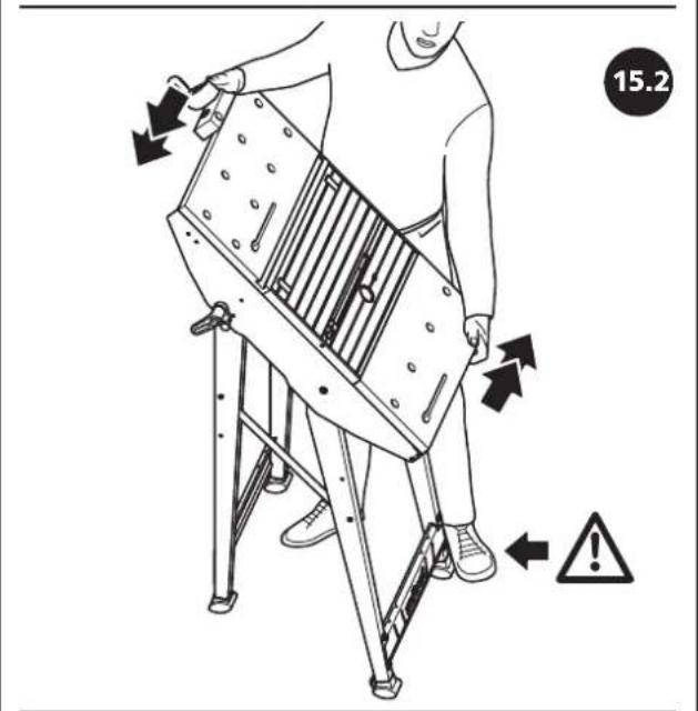
text_image
15.2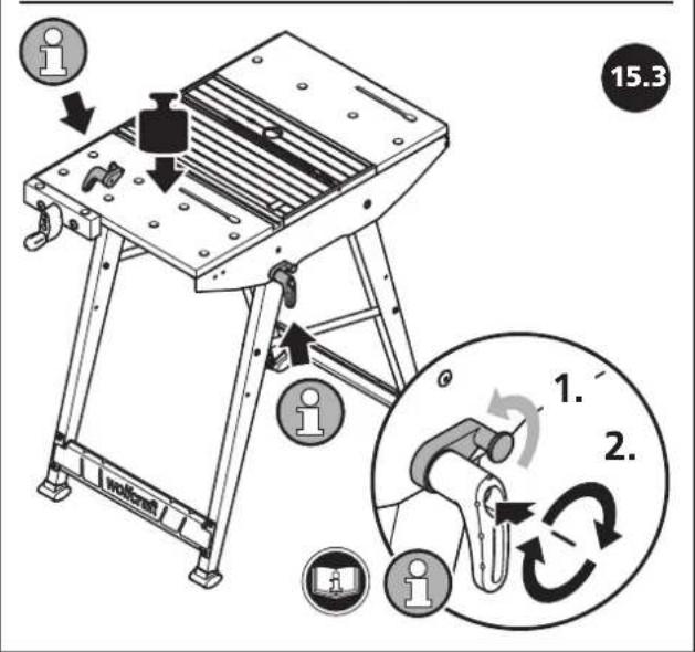
text_image
15.3 1. 2.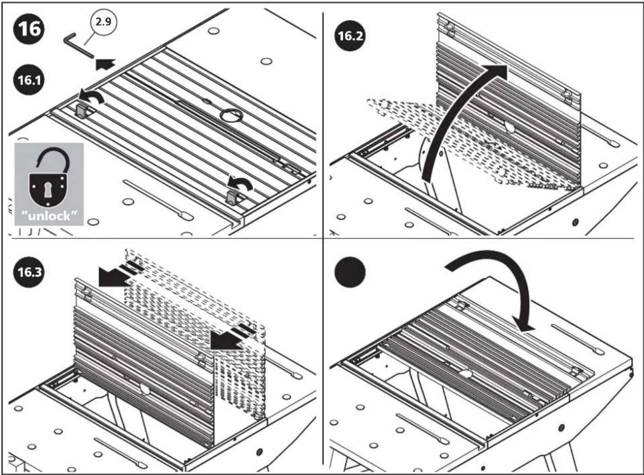
text_image
17 17.1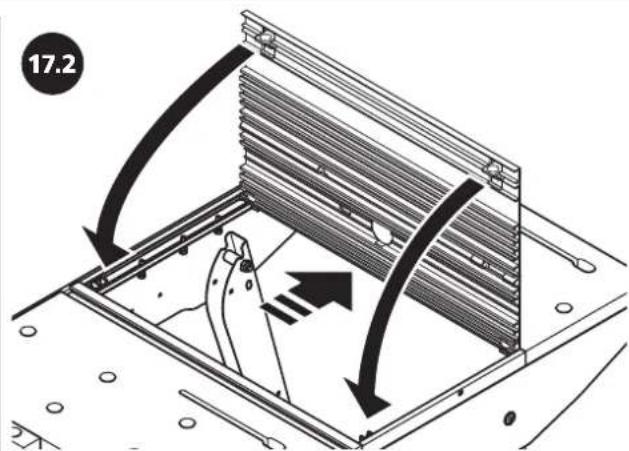
text_image
17.2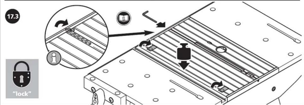
text_image
17.3 "lock"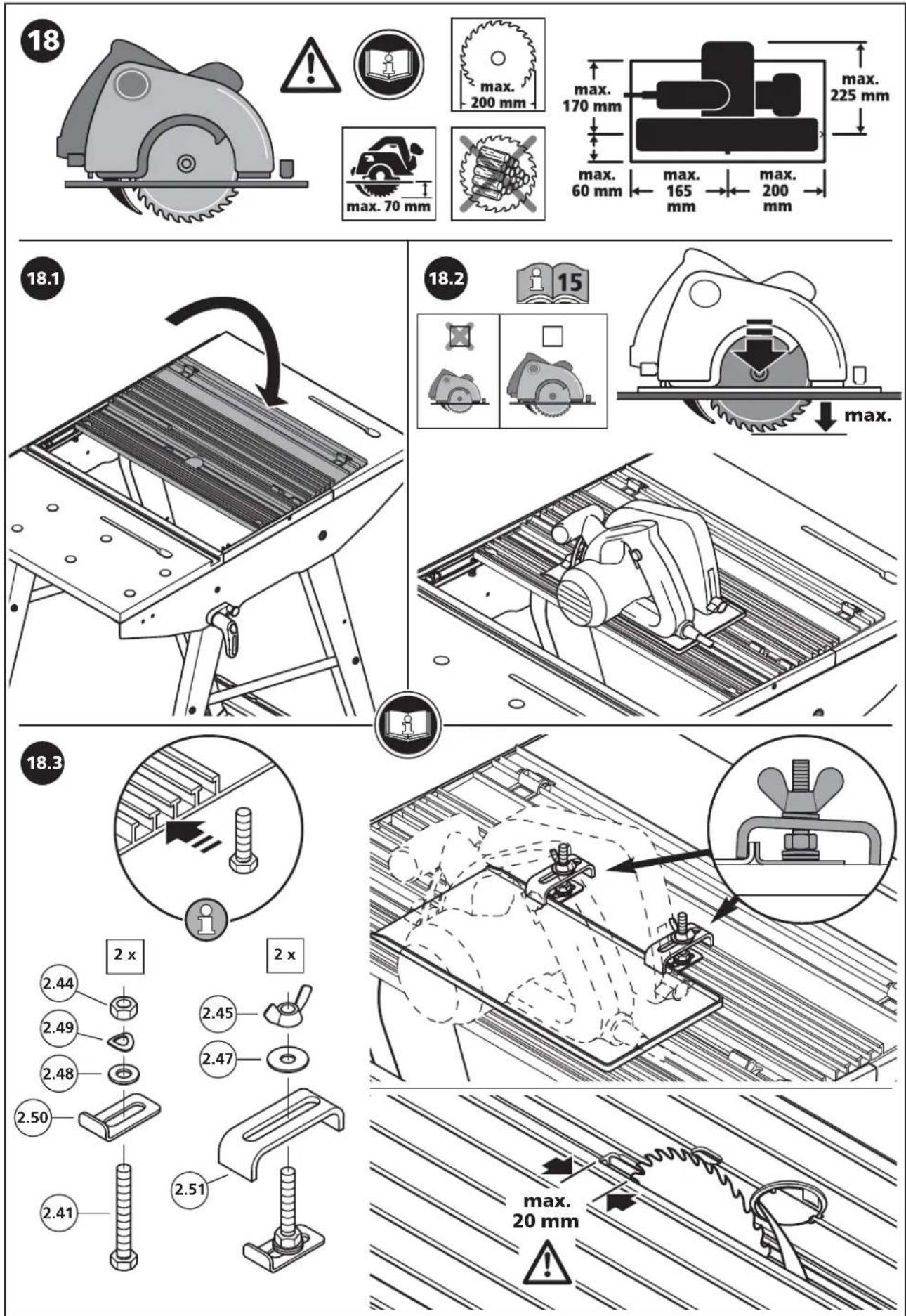
text_image
Technical diagram of a mechanical assembly with numbered parts and exploded view, showing internal components and assembly details.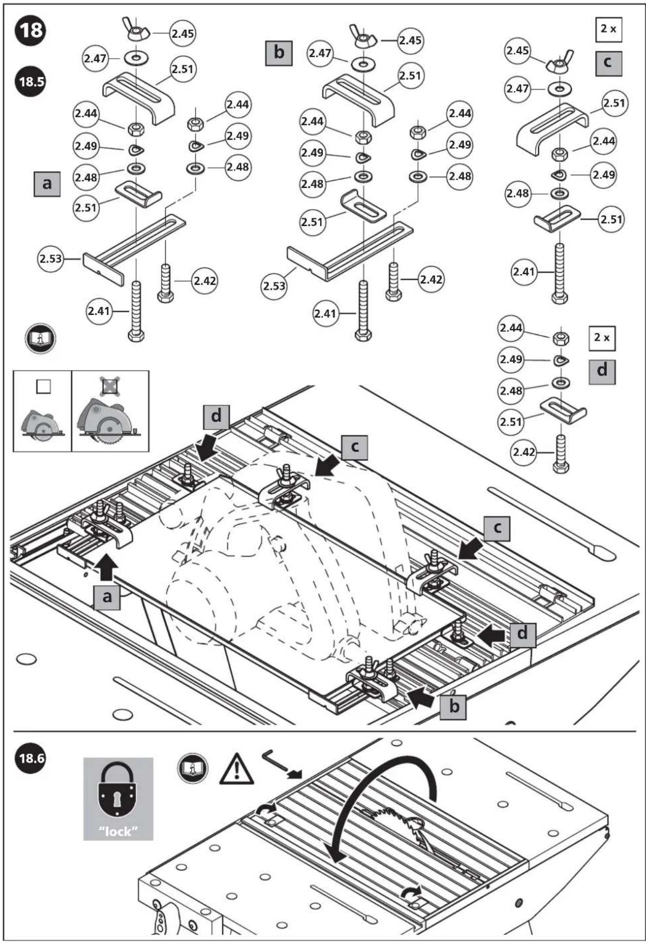
text_image
18 18.5 a 2.47 2.45 2.51 2.44 2.49 2.48 2.51 2.53 2.42 2.41 b 2.47 2.45 2.51 2.44 2.49 2.48 2.51 2.53 2.41 2.42 2.45 2.47 2.51 2.44 2.49 2.48 2.51 2.41 2 x c d 2.44 2.49 2.48 2.51 2.42 a d c c d b 18.6 "lock"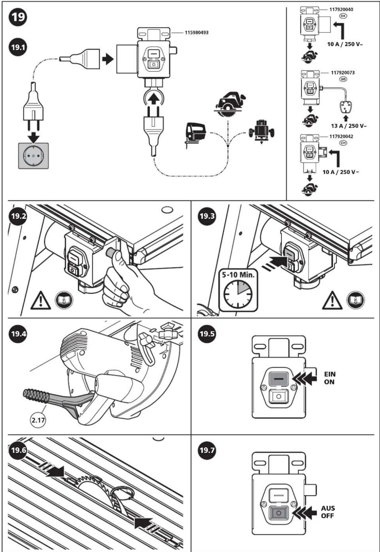
text_image
20 20.1 2.20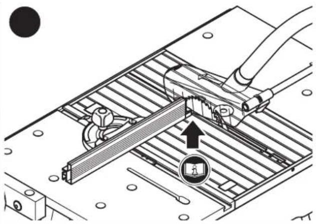
natural_image
Technical diagram of a mechanical assembly with tool and component, no visible text or symbols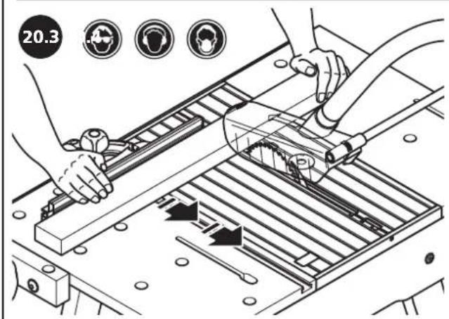
text_image
20.3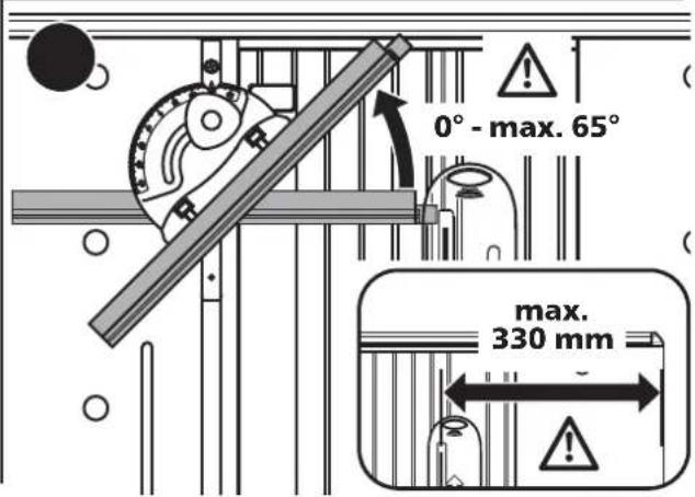
text_image
0° - max. 65° max. 330 mm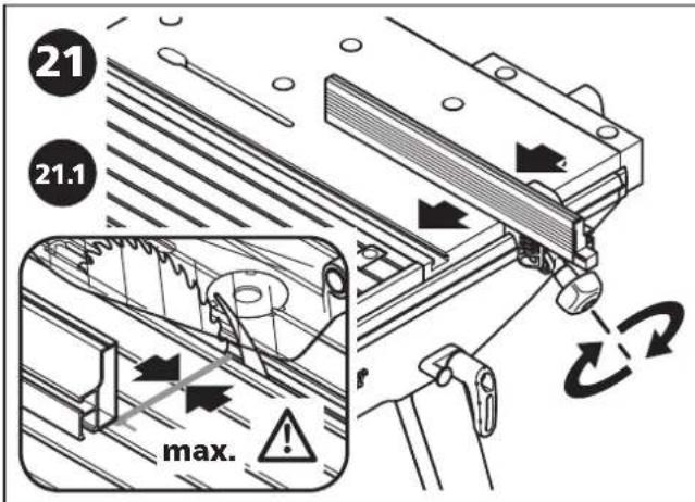
text_image
21 21.1 max.
text_image
21.2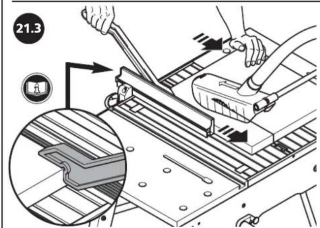
text_image
21.3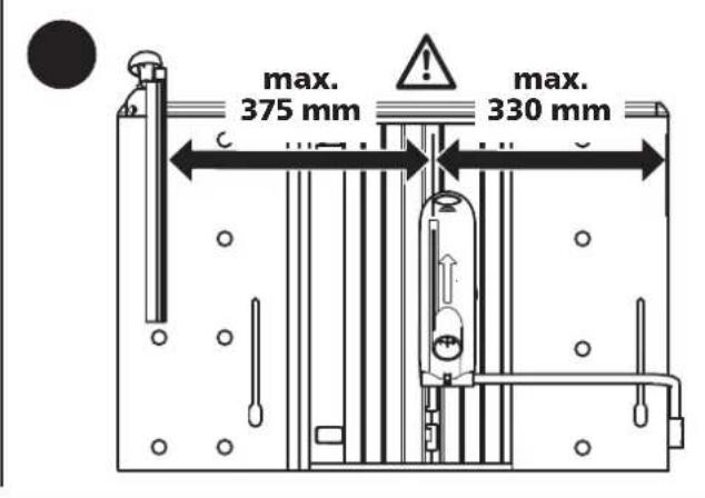
text_image
max. 375 mm max. 330 mm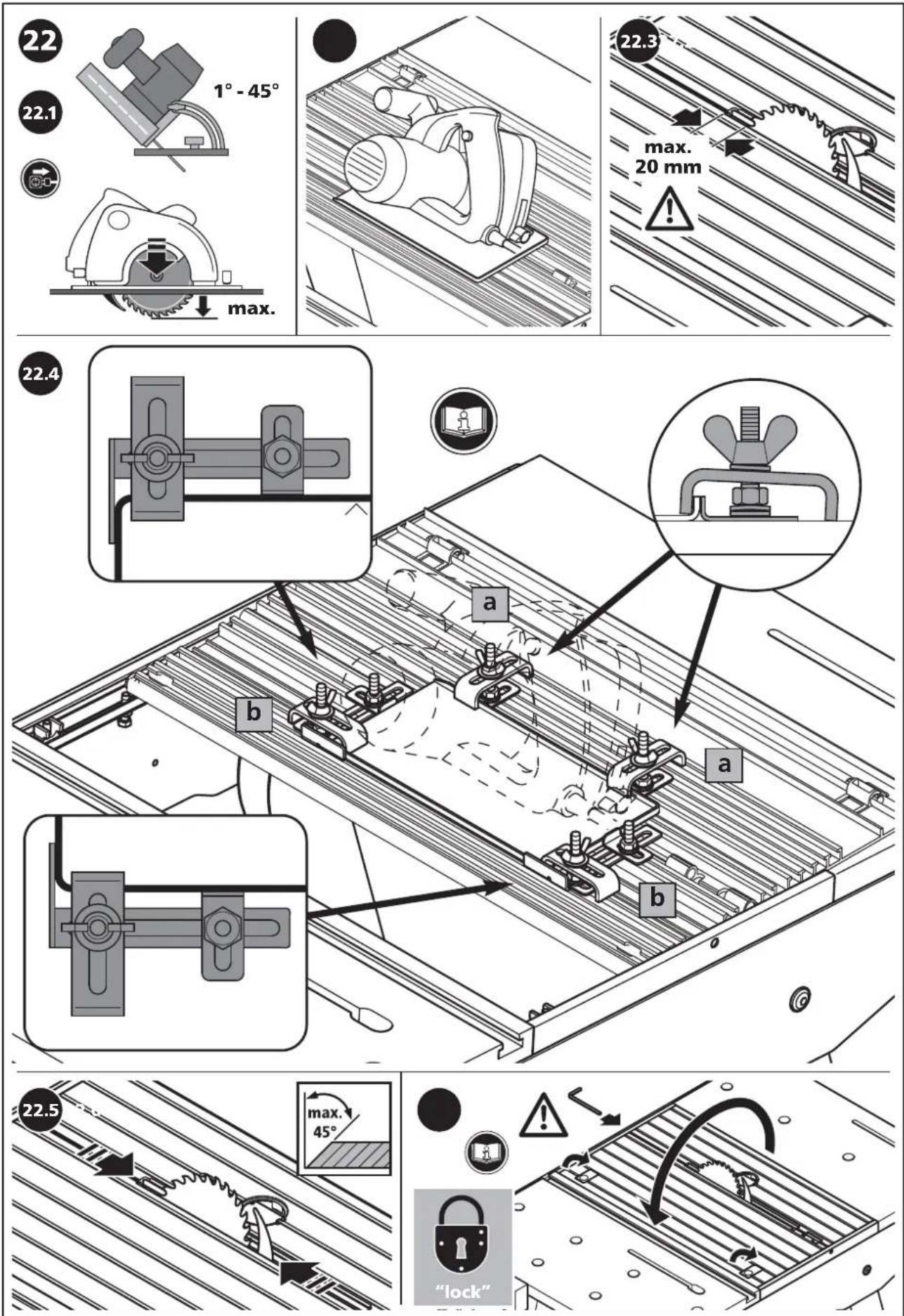
text_image
23 23.1 23.3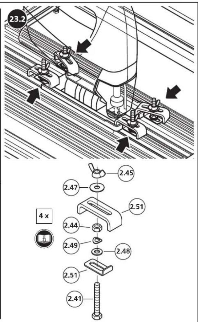
text_image
23.2 2.45 2.47 2.51 4 x 2.44 2.49 2.48 2.51 2.41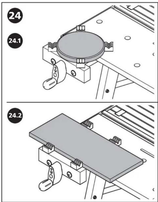
text_image
24 24.1 24.2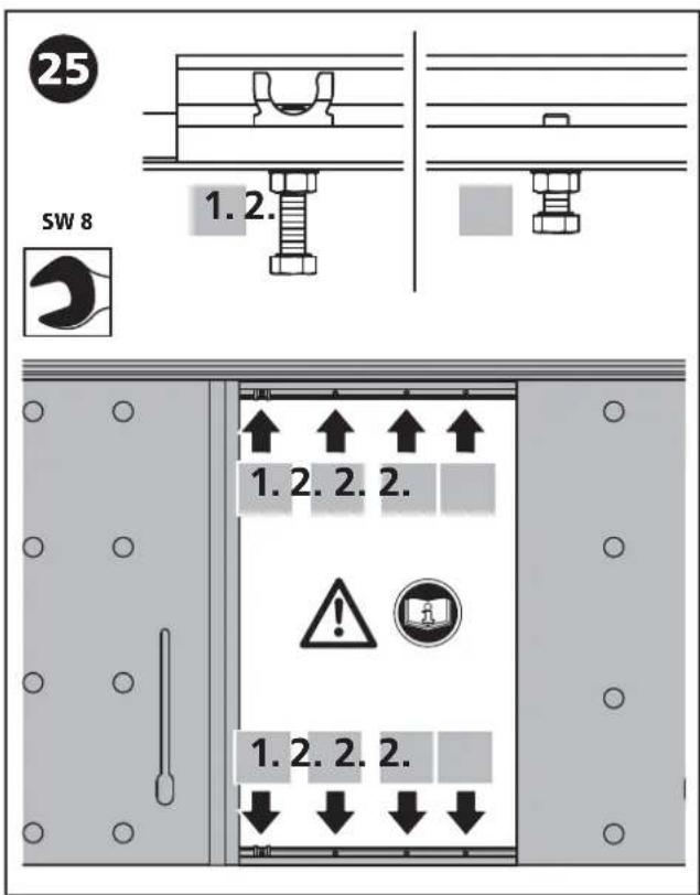
text_image
25 SW 8 1.2. 1.2.2.2. 1.2.2.2. ↓ ↓ ↓ ↓© Ersatzteilliste
① Spare parts list
⑤ Liste de pièces de rechange
E Lista de recambios
NL Lijst met reserveonderdelen
text_image
Exploded view diagram of a mechanical assembly with labeled components and part numbers© Zubehörbeutel
GB Accessory bag
F Sachet avec accessoires
E Bolsa de accessorios
NL Zakje met accessoires
① Sacchetto di accessori
P Saco de acessórios
OK Tilbehørspose
⑧ Tillbehörspase
FIN Lisätarvikepussi
natural_image
Isometric line drawing of a mechanical bracket with mounting holes and mounting holes (no text or symbols)
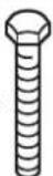
119916906
4x
M 6 x 16
DIN 912

natural_image
Technical line drawing of a mechanical tool with a 1x ratio label (no text or symbols on the tool itself)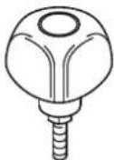
1x
1x
1 x

119926906
2x
M8x70
DIN 931
4 x
M 6 x 40
DIN 7985
2x
M 6 x 25
DIN 7985
8x
M 6 x 10
DIN 7985

4 x
8,4 DIN 9021

2x

2 x
6,4
DIN 125

2 x
M8
DIN 985

4 x
M 6
DIN 985
4 x
M6
IN 985
10
M6
0IN 934


2 x


119936906
4 x
M 6 x 25
DIN 933
6x
M6×12
DIN 912

8 x
M6
DIN 934

4x
M6

6x
M6
DIN 557

4 x
6,4 DIN 9021

9x
6,4
DIN 125
8 x
6.0
DIN 137
natural_image
Simple line drawing of a mechanical component with a 1x label (no text or symbols on the object itself)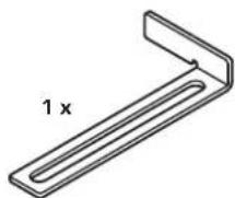
© Zubehör separat erhältlich
© Accessories not included
⑤ Accessories vendus séparément
E Accesorios no incluidos
NL Accessories separaat verkrijgbaar
① Accessori non compresi
© Accéssoirios vendidos separamente
©k Tilbehør som fåer separat
natural_image
Technical line drawing of a mechanical assembly with no visible text or symbols6903 000, 6904 000
wolfcraft®
A
text_image
6903 000 min. 2,4 mm max. 2,8 mm max. 160 mm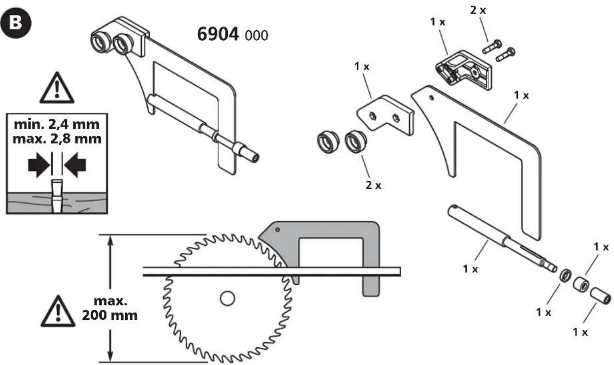
text_image
B 6904 000 min. 2,4 mm max. 2,8 mm max. 200 mm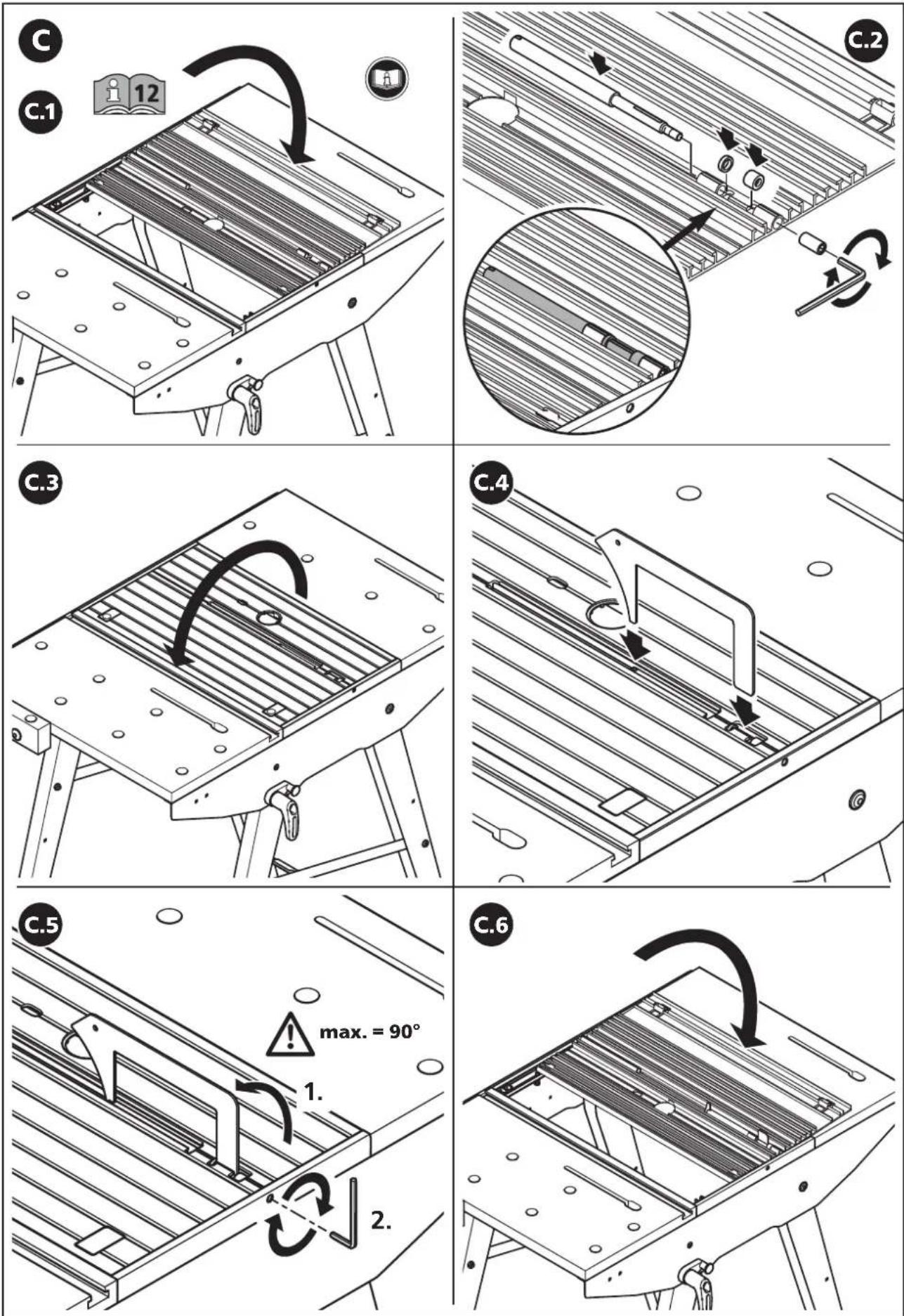
text_image
D D.1 max. max. 20 mm D.2 2 x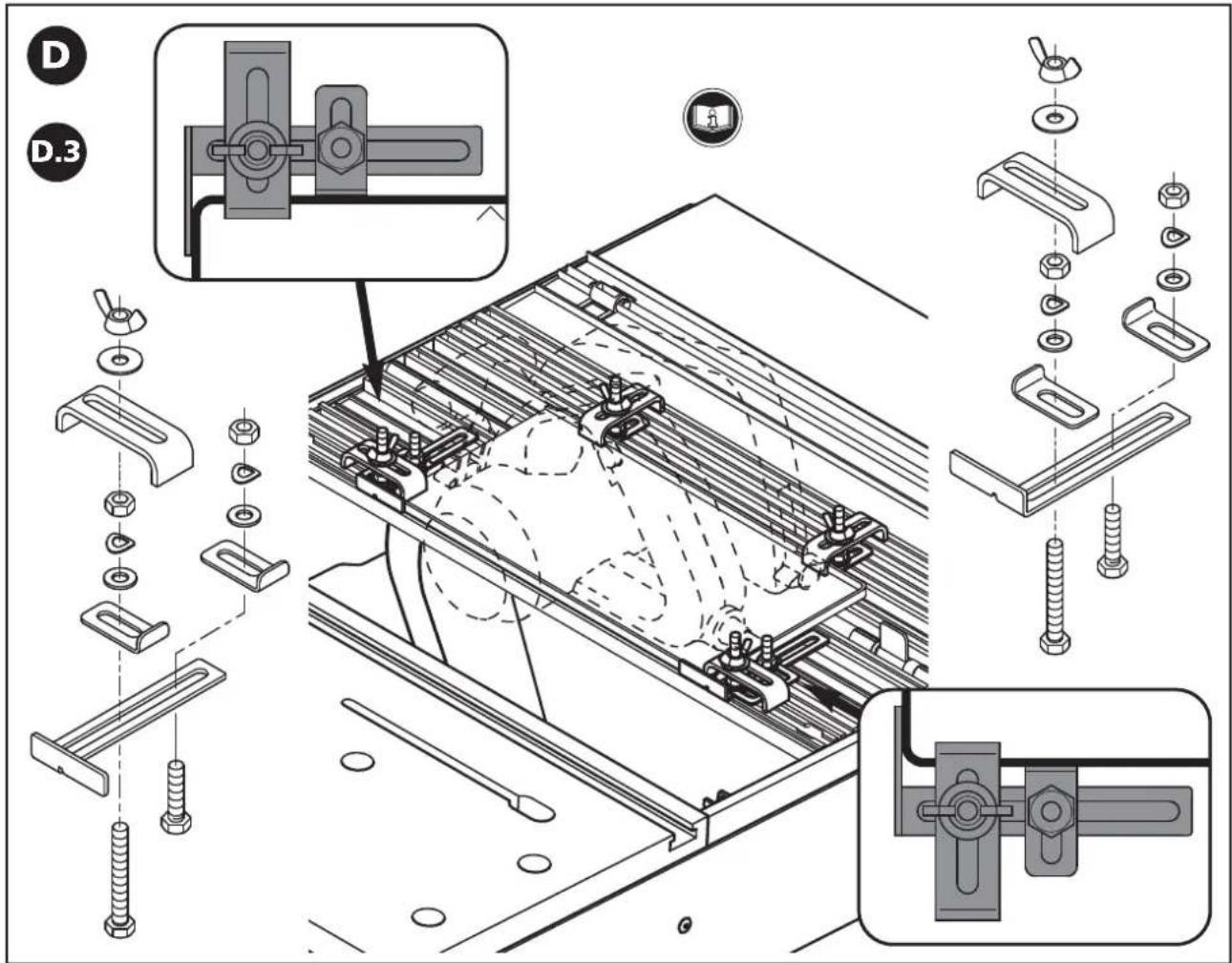
text_image
Technical diagram illustrating assembly steps of a mechanical component with labeled parts and exploded views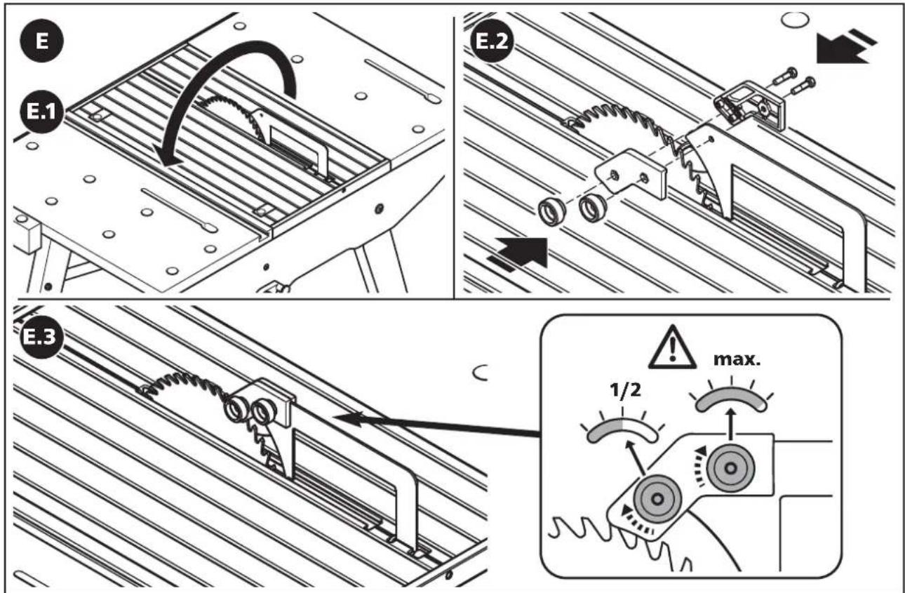
text_image
E E.1 E.2 E.3 max. 1/2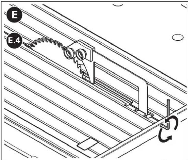
text_image
E E.4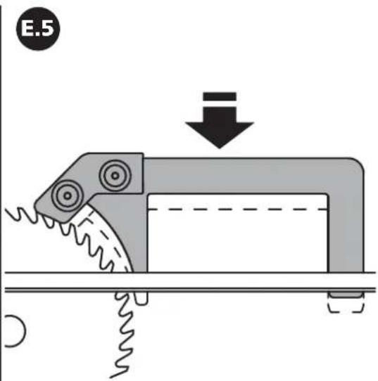
text_image
E.5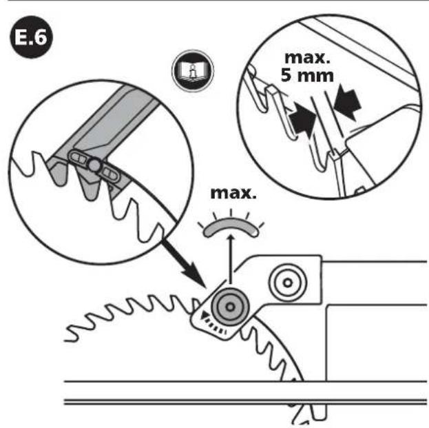
text_image
E.6 max. 5 mm max.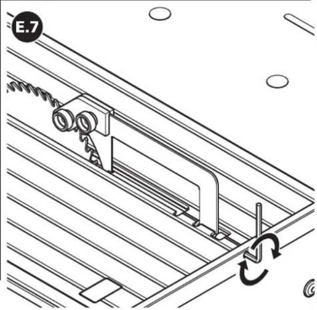
natural_image
Technical line drawing of a mechanical assembly with rotating components and a labeled section E.7 (no text or symbols beyond label)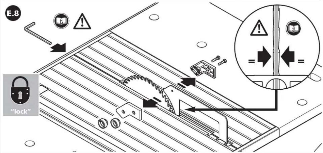
text_image
E.8 "lock"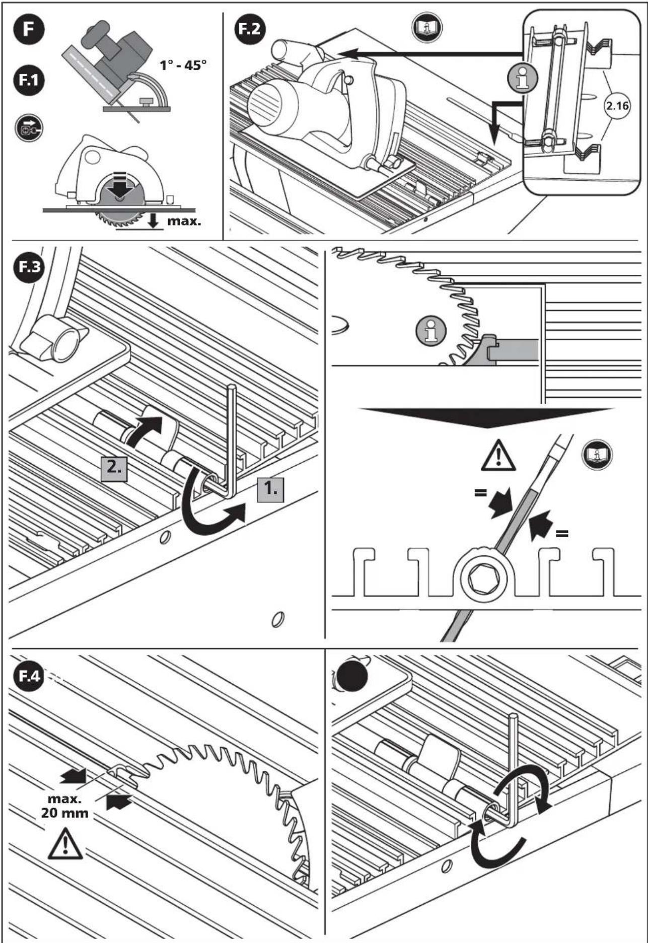
text_image
Technical diagram of a mechanical assembly with numbered components and an inset view of a clamp device.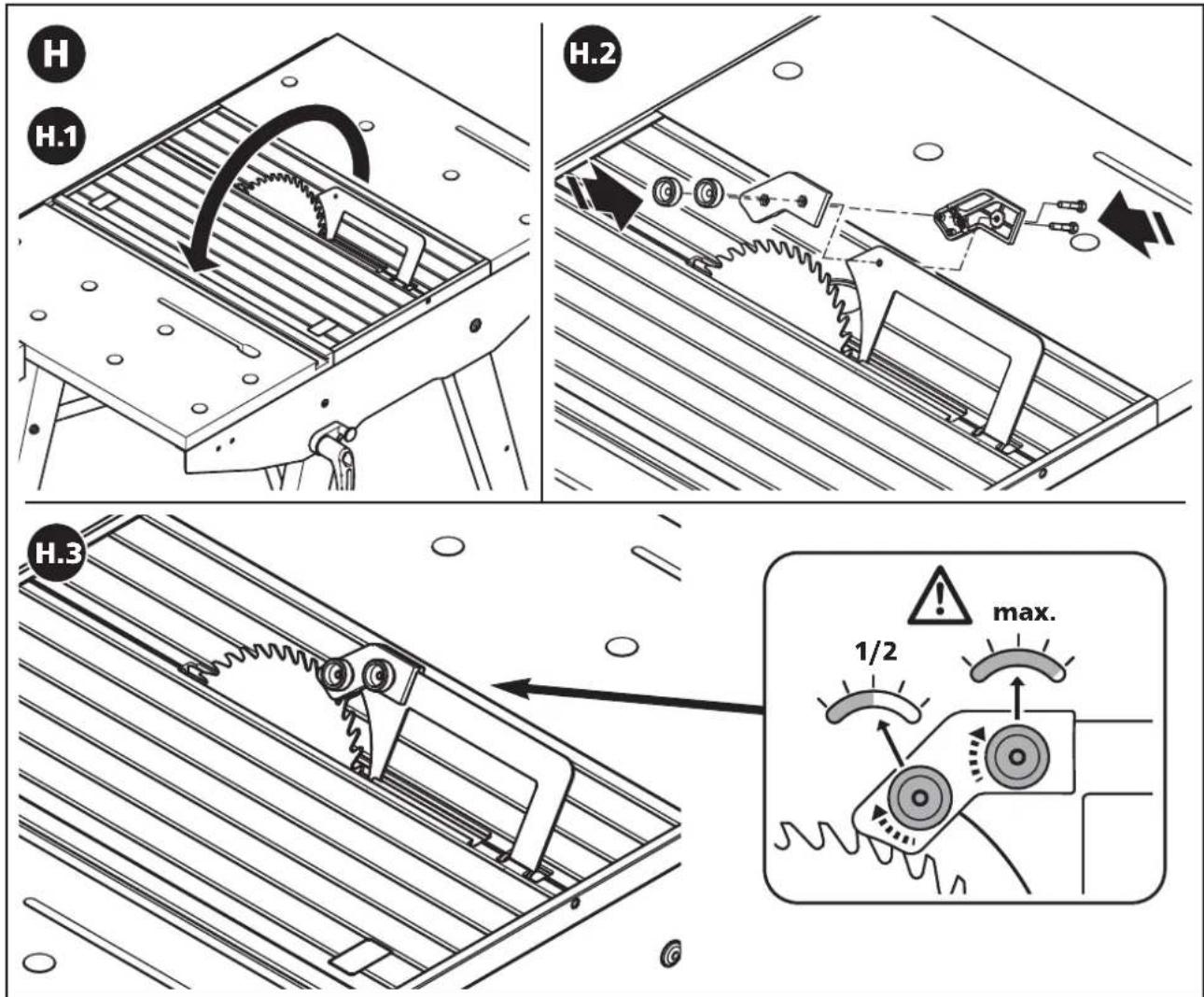
text_image
H H.1 H.2 H.3 max. 1/2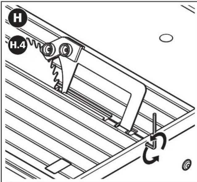
text_image
H H.4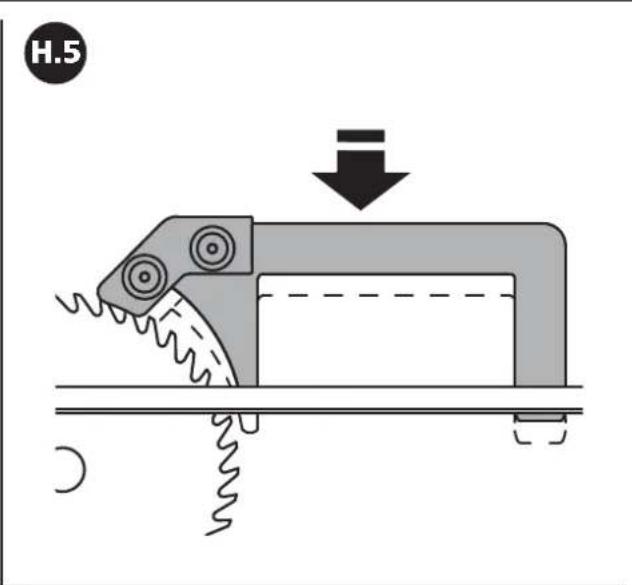
text_image
H.5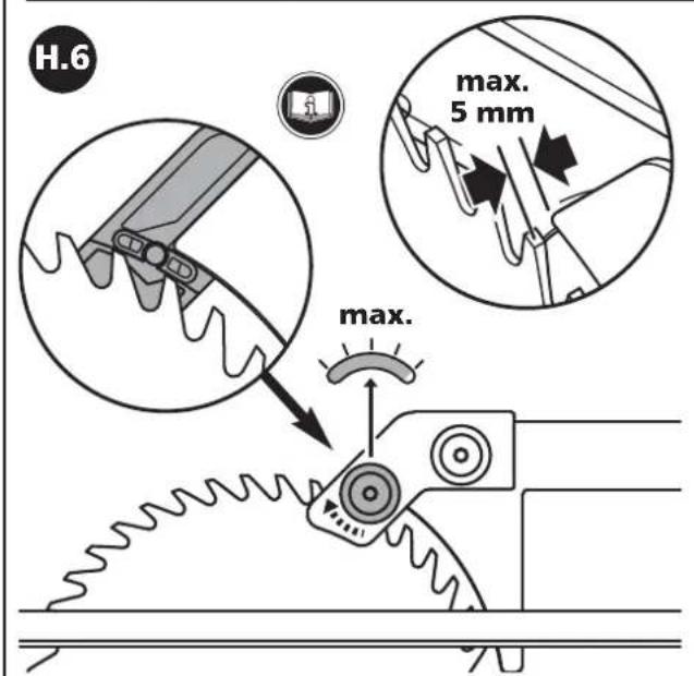
text_image
H.6 max. 5 mm max.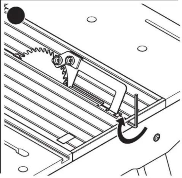
natural_image
Technical line drawing of a mechanical assembly with spring-loaded components and a curved arrow indicating motion (no text or symbols)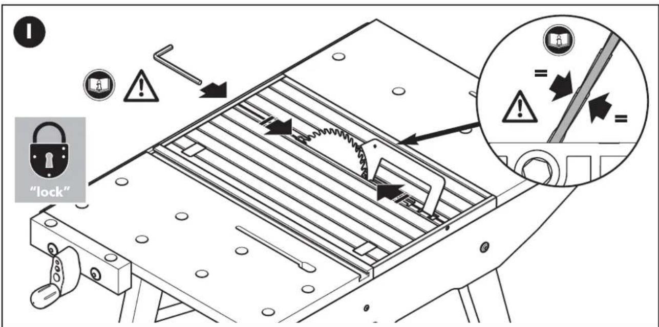
text_image
"lock"D
EINLEITUNG
- PLEASE NOTE: Do read all safety & other instructions that have come with the Master cut 1500 and with the power tools you use for work. Failing to observe the safety & other instructions may cause electric shocks, fire and/or severe injuries.
- Do keep the operating instructions for future reference in a safe place.

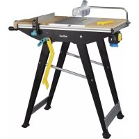
TECHNICAL DATA
dimensions (put up for use): 780 x 520 x 863 mm (width x depth x height) dimensions (folded up): 1335 x 520 x 260 mm worktop: 780 x 500 mm maximum height of work piece: circular saw bench 60 mm maximum cutting width with parallel guide: circular saw bench 375 mm diameter of the clamping holes: 20 mm load-bearing capacity: 200 kg weight: 17 kg

SYMBOLS AND THEIR MEANING

Warning against a general danger

Do not use the machine for cutting firewood.

Read the instructions!

Use only hand circular saws with a maximum cutting depth of 70 mm.

Goggles must be worn.

Use only saw blades with a maximum diameter of 200 mm for your hand circular saw.

Hearing protection must be worn.

Set the cutting depth of your hand circular saw before every cut in such a way that the saw blade does not protrude more than 4 mm from the work piece.

Dust mask must be worn.

Use only hand circular saws with a riving knife.

Pull the plug.

Use only machines with a maximum output of 2760 W.

General information
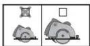
The pictogram indicated refers to the machine plate dimensions of the circular hand saw (smaller or larger base plate dimensions).

ASSEMBLY TOOLS

1 allen wrench: SW 5 (included in the scope of delivery)

2 screw drivers: PH 1, PH 2 (not included in the scope of delivery)

3 hexagon wrenches: SW 8, 10, 13 (not included in the scope of delivery)

INTENDED USE
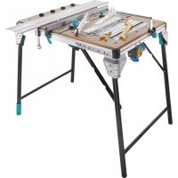
The MASTER cut 1500 is a multifunctional work and machine table. It is suitable for:
- mounting a circular hand saw with riving knife on the machine plate with a max. 200 mm saw blade diameter and max. 70 mm cutting depth. Do not use saws with base plate dimensions greater than the maximum values indicated (see Fig. 18). It makes the MASTER cut 1500 a stationary circular saw bench.
- use as a circular saw bench for circular hand saws without a riving knife. Only in conjunction with separate riving knife accessory, art. no. 6903000 with max. 160 mm saw blade diameter and min. 2.4 mm cutting width.
- use as a circular saw bench for circular hand saws without a riving knife. Only in conjunction with separate riving knife accessory, art. no. 6903000 with saw blade diameters from min. 161 mm to max. 200 mm, a cutting width from min. 2.4 mm and a max. cutting width of 66 mm.
- use as a jigsaw table.
- use as a milling table only in conjunction with the parallel milling guide, art. no. 6901000 and for 230 V routers with a maximum rating of 1800 W. Do not use cutters with a diameter of more than 27 mm!
- Use as a working table for machining workpieces (e.g. drilling, sanding, etc.).
- Observe the manufacturer's safety instructions for the machines used as well as the safety instructions for the machine table.
- When disposing of the MASTER cut 1500, please observe the local disposal regulations.
The user is liable for any damage or accidents resulting from improper use.
GB
GENERAL SAFETY INSTRUCTIONS
- Keep your workplace clean and well lit. Poor housekeeping or unlit working areas may result in accidents.
- Do not work with power tools in an explosive ambience, where flammable liquids are kept and where gas or dust occur. Power tools will generate sparks which might ignite the dust or vapours.
- Keep children and other persons off your workplace, while using power tools. When getting distracted you can lose the control over the equipment.
- The plug of the power tool must fit into the socket. The plug must not be tampered with. Do not use adapters together with grounded power tools. Unmodified plugs and matching sockets will reduce the risk of getting an electric shock.
- Keep power tools out of the rain and away from wetness. Water penetrating into a power tool will heighten the risk of getting an electric shock.
- When working with a power tool outside, use only extension cords that are suitable for outdoor use. Using an extension cord that is suitable for outdoor use will reduce the risk of getting an electric shock.
- If it is unavoidable to use a power tool in a wet ambience, use a residual-current circuit-breaker. It will reduce the risk of getting an electric shock.
• Take care of what you do and handle the power tool with care. Never use a power tool, when you feel tired or when you are under the influence of drugs of any kind or alcohol. One moment of inat-tentiveness while using the power tool can cause severe injuries.
- Do wear suitable personal protective clothing and equipment, such as hearing protection, goggles, dust masks while doing dust-generating jobs as well as protective gloves, when processing rough materials and when changing tools.
- Remove the setting tools or wrenches before switching on the power tool. A tool or wrench attached to a rotating part of the equipment may cause injuries.
- Wear suitable clothes, i.e. no loose garments or jewellery. Keep your hair, clothing and gloves away from rotating parts. Loose garments, jewellery or long hair may be caught by such rotating parts.
• Always use the protective hood with the dust extractor.
- Do not use power tools with a defective switch. A power tool that can no longer be switched on or off is dangerous and needs repairing.
- Keep unused power tools out of the reach of children. Do not allow persons using equipment which they are not familiar with it, or persons who have not read these instructions. Power tools pose a danger, when being used by inexperienced persons.
- Check before starting to work, whether equipment and tools function properly. Never work with damaged or blunt tools.
• Have your power tools only repaired by duly qualified personnel. Demand original spares, so that the safety of the power tool remains ensured.
- Pull the plug from the socket and/or remove the battery pack from the power tools before you change the setting of your equipment or before you replace any components. The unin-tentional re-start of a power tool may cause accidents.
- Put up the machine table properly before installing the power tool. The table's safe assembly is vital to prevent it from collapsing.
- Attach the power tool safely to the machine plate before using it. If the power tool gets out of place on the machine plate, you may lose control of it.
- Put the machine table on a firm, plain and horizontal surface. If the machine table can shift or wobble, neither the power tool nor the work piece can be moved safely and steadily.
- Do not overload the machine table and do not use it as ladder or scaffolding. Excess loads or standing on the machine table can shift the table's centre of gravity upwards, so that it may topple over.
- Do not process any other materials than wood or easily machinable plastic. Exception: It is also allowed processing easily machinable metals (e.g. aluminium), but only with the jig-saw and a suitable saw blade
- Loose splinters, chips or similar residues must not be removed by hand from the area close to the running saw blade!
- The machines used must conform to DIN EN 60745-1. Equipment built after 1994 must bear the CE sign.
- Do not merely saw by hand without a guiding aid; use the parallel or the angle guide.
- Saw blades must not be slowed down by pushing from the side after the drive has been deactivated!
- Use the tools for their intended purpose only.
- Use only faultless saw blades; the base body must not be thicker and the width of the set of teeth not narrower than the thickness of the splitting wedge.
- Make regular checks, whether all screws are tightened firmly!
- Never use your workbench in an improper way or for purposes other than intended!
- Remove all objects from the workbench that are not required.
- Do not use the machine for cutting firewood.
- Do not use the machine table for cutting log wood.
- The power tools must only be switched on and off via the safety switch.
- Use only the switch clamp supplied to permanently fix the appliance switch in the „ON“ position.
• Always use a push stick when processing small or narrow work pieces.
- When not in use, hang the push stick on the bracket provided (Fig. 8).
- Make sure that the two swivelling brackets for securing the table legs are seated correctly with the safety bolts inserted in the holes in the side section and that the knurled screws are firmly tightened (Fig. 15.3).
- Before starting work, make sure that the hand-held circular saw, router or jigsaw is properly attached to the machine plate, the machine plate is safely arrested in the notch on the machine table and the Allen wrench is inserted for additional safety (Fig. 17.3).
- Do not use the machine outdoors in the rain.
- Observe the maximum permitted workpiece dimensions (see Technical data).

SAFETY INSTRUCTIONS FOR CIRCULAR SAWS
- Apart from these machine-specific safety instructions, do also observe the safety instructions for the hand-held circular saw you work with.
- Only use hand-held circular saws with splitting wedge, with a maximum saw blade diameter of 200 mm and a maximum cutting depth of 70 mm.
- Use only saws within the above maximum dimensions for the base plate (see Fig. 18).
- Use the circular saw bench only, when the protective hood is properly fixed.
- CAUTION: Make sure that the saw blade has been installed parallel to the opening in the saw gap and realign the hand-held circular saw, if necessary.
• Support long work pieces at the removal side, so that they rest in a horizontal position; e.g. with a wolfcraft roller trestle (Art. No. 6119973).
- Avoid overloading the hand-held circular saw.
- Do not use grinding pads.
- Use only recommended brands of saw blades and select them depending on the material to be sawn.
• DANGER: Keep your hands off the sawing area and the saw blade.
- Never reach under the work piece. The protective hood cannot protect you from the saw blade underneath the work piece.
- Adapt the cutting depth to the thickness of the work piece; less than a full tooth height should be visible under the work piece.
- Be always aware that the work piece can be caught by the running saw blade and hit the operator.
- A back stroke is the result of using the saw incorrectly and/or for a wrong application. It can be prevented by suitable precautionary measures, as described below.
GB
- Keep the saw firmly with both hands and put your arms in a position, so that you can ab-sorb the back stroke forces. Always stand to the side of the saw blade; never align your body with the saw blade. In the event of a back stroke, the circular saw can jump backwards, although the operator should be able to master the situation by taking suitable pre-cautionary measures.
- Should the saw blade be jammed or should you interrupt your work, always switch off the saw and keep it steady in the material until the saw blade has come to a standstill. Never try to remove the saw from the work piece or pull it backwards, as long as the saw blade is rotating, as this may result in a back stroke. Find out the reason why the saw blade is jammed and eliminate the cause.
- If you wish to re-start a saw that is still in the work piece, centre the saw blade in the saw gap and check, whether saw teeth might be blocked in the work piece. If the saw blade jams, it may free itself from the work piece or cause a back stroke during the re-start of the saw.
- Support large plates, in order to minimize the risk of a back stroke caused by a jammed saw blade. Large plates may bend under their own weight. Plates must be supported on both sides, both near the saw gap and at the edge.
- Do not use blunt or damaged saw blades. Saw blades with blunt or incorrectly set teeth will increase the friction at the narrow saw gap, cause the saw blade to jam and may result in a back stroke.
- Set and fix the cutting depth and the cutting angle before starting to saw. If the settings change during the sawing, the saw blade may get blocked and cause a back stroke.
Take extra care when making a "plunge cut" into an existing wall or other concealed areas. The immersing saw blade may block in concealed objects and cause a back stroke.
• Always use the push stick when cutting slashes and joints, since the saw blade is not visible.

SAFETY INSTRUCTIONS FOR JIGSAWS
- Apart from these machine-specific safety instructions, do also observe the safety instructions for the jigsaw you work with.
- Never work with a damaged jigsaw.
- Avoid overloading the jigsaw.

PLEASE NOTE: USE THE MILLING TABLE EXCLUSIVELY IN COMBINATION WITH THE PARALLEL MILLING GUIDE (ART. NO. 6901000)
SAFETY INSTRUCTIONS FOR ROUTERS
- Apart from these machine-specific safety instructions, do also observe the safety instructions of the router you work with.
- Be always aware that the work piece may unexpectedly get out of control during the mill-ing process and strike back.
- Do not use the machine table for curved work!
- Therefore, carry out the milling work exclusively with the parallel milling guide (which is available as accessory under Art.-No. 6901000), in order to prevent back strokes and to protect your hands from touching the cutter.
- Observe the original operating instructions for the parallel milling guide (Art.-No. 6901000), in order to be able to install it correctly.
- Do not use routers with a rating of more than 1800 W and a voltage of more than 230 V.
- Do not use cutters with a diameter of more than 27 mm!
- Please observe that the feed must be against the cutter's direction of rotation.
- Select the spacer rings supplied in relation to the size of the milling tool. Safe work requires selecting the smallest possible spacer ring.
- Use only sharp and properly maintained milling tools that have been set in accordance with the tool manufacturer's instructions.
- Observe the data concerning the minimum/maximum speed and the direction of rotation indicated directly on the equipment and tools used, or on their packaging, or as detailed in the operating instructions.
- Please be aware that the improper use of milling tools, of work pieces and of the guiding devices for the work piece may cause dangerous situations.
- Keep your hands off the milling tool, when milling close to the guide.
- If possible, use table pressure shoes in addition to the parallel milling guide while milling.
- Support long work pieces on the removal side, in order to avoid dangerous situations that may be caused by the uncontrolled tilting of the work piece. The support must rest on stable ground and have the same height as the machine table, e.g. the roller trestle (Art. No. 6119973).
- Do only process work pieces that, considering their weight, can be held and advanced safely by one person.
- Choose the correct speed that is appropriate for tool and work piece. Please refer to the operating instructions of your router for the correct speed parameters.
- Observe the admissible maximum dimensions for the work pieces (see Technical data).

SCOPE OF DELIVERY
Take the Master cut 1500 out of the cardboard box and check whether the contents are complete and all pictured parts are included (Fig. 1, Fig. 2).

BASIC ASSEMBLY
Installation of the table: Place the top section of the table on a flat, clean surface. Secure the front pair of legs and lower strut using all fixing parts as shown in the illustration. Make sure that the two locking levers are seated correctly in the retaining holes and both knurled screws are firmly tightened (Fig. 3.1). Then mount the rear pair of legs and the second lower strut. Secure the two cross struts to the front pair of fixed legs, then fold the rear pair of legs upwards and attach the other end of the two cross struts (Fig. 3.2). Now attach the two cushion feet with wheels to the rear pair of legs as illustrated and the other two feet to the front pair of legs (Fig. 3.3).
CAUTION: Make sure that the fixing parts marked with an information symbol are only tightened to such an extent that the table can be folded up with minimal resistance. Always check that both safety brackets are engaged and both knurled screws are firmly tightened.
The table can now be set down on its legs.
CAUTION: Take care not to pinch your hands when folding up and unfolding the table or swivelling the machine plate.
Vice: Mount the vice to the machine table as illustrated. The vice can be mounted on the right or left side (Fig. 4).
Safety switch: Mount the safety switch to the machine table as illustrated (Fig. 5).
GB
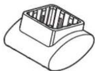
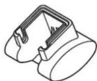
Protective hood: Assemble the individual components of the protective hood first. Then slide the protective hood holder with the guide into the aluminium profile and tighten the two Allen screws using the Allen wrench (Fig. 6).
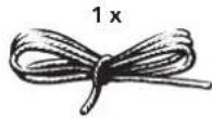
Switch clamp: Knot one end of the cord in the hole of the switch clamp and the other end with the protective hood holder (Fig. 7).
Push stick: Put the push stick on the holder (Fig. 8).
Angle guide: Mount the angle guide as illustrated (Fig. 9). The aluminium rail may have to be adjusted depending on the height of the workpiece. Vertical with a minimum workpiece height of 15 mm (Fig. 9.1), horizontal with a maximum workpiece height of 15 mm (Fig. 9.1). The angle guide directs the workpiece into the guide groove (Fig. 9.3).
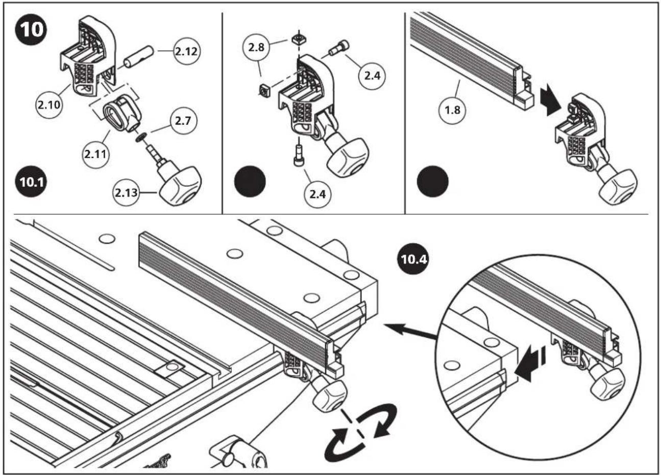
Parallel guide: Mount the guide holder as illustrated (Fig. 10.1). Assemble the two screws and square nuts only loosely (10.2). Slide in the aluminium guide as illustrated and tighten the screws (Fig. 10.3). Then slide the parallel guide into the slot and tighten the knurled screw (Fig. 10.4).
CAUTION: Lock the machine plate: The Allen wrench is used to lock the machine plate and must be inserted in the table in the "lock" position as illustrated before starting work (Fig. 11).
Spacer rings: The two spacer rings are designed to increase safety during routing. Always select the smallest possible spacer ring for the cutter being used (Fig. 12).
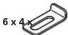
Clamping claws: Insert the clamping claws in the predrilled holes and use in conjunction with the vice to secure your workpieces.

FOLDING UP AND UNFOLDING THE TABLE
CAUTION: Before folding up the table, always disconnect the mains plug and appliance inlet from the safety switch!
Folding up: Slacken both knurled screws enough to allow the two locking levers to be retracted and turned (Fig. 14.1). Then fold the table in the direction of the arrow. For your own safety, always rest your foot against one of the cushion feet as illustrated to ensure that the table cannot slip (Fig. 14.2). The wheels on the cushion feet are used to transport the table more easily (Fig. 14.3).
Unfolding: Hold the table securely with both hands and rest your foot against one of the cushion feet as illustrated (Fig. 15.1). Now tilt the table in the direction of the arrows in a single movement until it has unfolded completely (Fig. 15.2). Then push the front edge of the table down with one hand until the top section engages in position. Insert both locking levers into the holes and tighten both knurled screws (Fig. 15.3).

PREPARATIONS PRIOR TO INSTALLING MACHINES
CAUTION: The procedure for opening and closing the machine plate before starting work is described here and must be performed every time a machine is changed!
Opening the machine plate to install a machine: Remove the Allen wrench from the safety lock. Swivel both plastic levers upwards, hold the two levers and raise the machine plate slightly. Lift the machine plate in the direction of the arrow until it is vertical and slide forwards up to the guide. Then lay down the machine plate until it is resting safely on the table (Fig. 16).
CAUTION: When working with the machine plate, do not reach under the machine plate with your fingers (danger of injury).
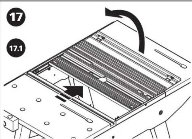
Closing the machine plate after successful machine installation: Raise the machine plate slightly. Then push all the way back to the rear guide and raise to a vertical position. Hold the machine plate by the two plastic levers and tilt the machine plate in the direction of the arrow until it reaches engagement position. Engage the machine plate from above and close both plastic levers. Insert the Allen key back into the safety socket to lock the machine plate (Fig. 17).

ASSEMBLY OF THE HAND-HELD CIRCULAR SAW
Open the machine plate as shown in Fig. 16.
Suitable hand-held circular saws: Please refer to Fig. 18 for the maximum dimensions permitted dimensions of hand-held circular saws. Always use circular hand saws with a riving knife, max. 200 mm saw blade diameter and max. 70 mm cutting depth.
Assembly and alignment of the hand-held circular saw: Retract the protective pendulum hood on the hand-held circular saw and position the machine centrally over the saw gap. Release the cutting depth lock on the circular saw and set the machine to the maximum cutting depth (Fig. 18.2). Tighten the cutting depth lock again. Align the blade on the circular saw centrally and parallel to the saw gap.
CAUTION: Check the distance between the foremost tooth on the saw blade to the front edge of the saw gap. This distance must be less than 20 mm.
Assembly example for machines with smaller base plates.
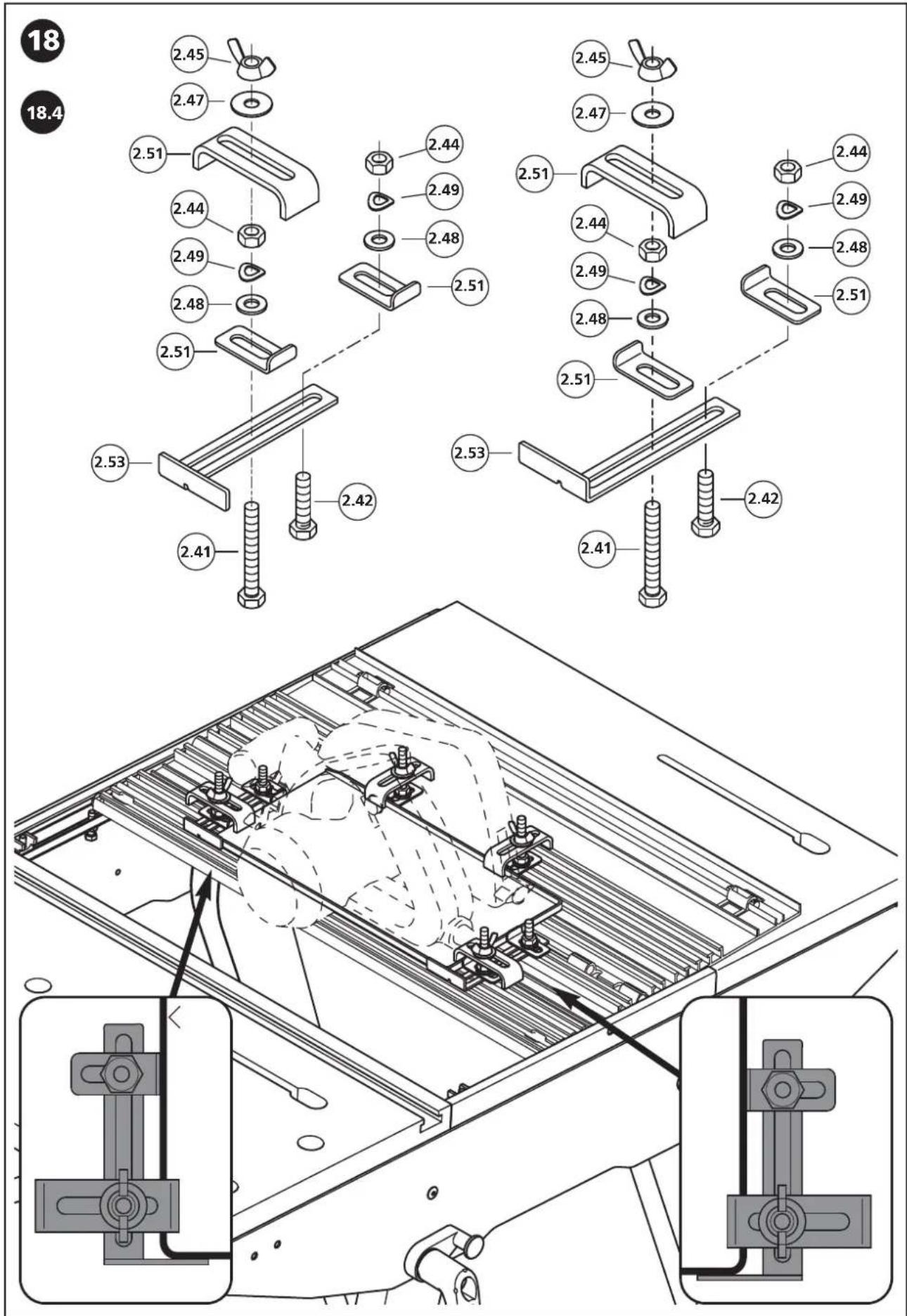
After aligning the machine, attach the two side stops so that their surfaces are in full contact with the machine's base plate. Then attach the two clamping claws (Fig. 18.3). Secure one side of the base plate. Install the angle bracket with two side stops first. Make sure they are in full contact with the base plate. In the same way, install an angle bracket with two side stops on the opposite side. Attach the two clamping claws (Fig. 18.4). The two clamping claws must be installed as close to the longer side of the base plate as possible.
Assembly example for machines with larger base plates.
After aligning the machine, attach the two side stops so that their surfaces are in full contact with the machine's base plate. Then attach the two clamping claws (Fig. 18.5 c). Install the two side stops as close to the longer side of the base plate as possible (Fig. 18.5 d). Attach the angle bracket to a side stop using a screw, washer, lock washer and nut (Fig. 18.5 b). Then attach the clamping claws. In the same way, attach an angle bracket to a side stop on the opposite side using a screw, washer, lock washer and nut (Fig. 18.5 b). Finally, attach the clamping claws (Fig. 18.5 a).
GB
Close and lock the machine plate as shown in Fig. 17.
CAUTION: Make sure that the saw blade has been installed parallel to the opening in the saw gap and realign the hand-held circular saw, if necessary.
Connection with the power supply: Plug the appliance inlet of the hand-held circular saw into the safety switch and an extension cord leading from the safety switch to the mains socket outlet (Fig. 19.1). The extension cord is not included in the scope of delivery.
CAUTION: Press the thermostatic switch before operating for the first time! If the power is interrupted due to excess voltage, wait 5 - 10 min. and press the thermostatic switch. The ON switch can then be pressed (Figs. 19.2, 19.3).
Press the red button (OFF) on the safety switch. Then attach the switch to the hand-held circular saw (Fig. 19.4). Now press the green button (ON) and check that the saw blade rotates freely in the gap insert (Fig. 19.6), then press the red button (OFF) again (Fig. 19.7).
CAUTION: Always pull out the mains plug if the table is not in use or when folding up the table.
The MASTER cut 1500 is now ready for use.

STATIONARY SAWING WITH THE HAND-HELD CIRCULAR SAW
CAUTION: Always work with the protective hood and switch on dust extraction at the protective hood.
Sawing with the angle guide
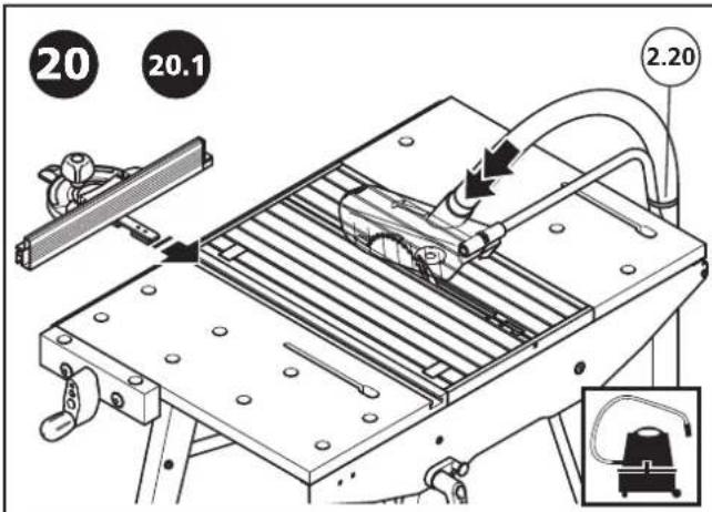
Slide the angle guide into the slot (Fig. 20.1). Make sure that the black end of the stop runs as closely as possible under the protective hood so that the hood can be lifted (Fig. 20.2). Now retract the angle guide and rest the workpiece against the angle guide. Switch on the hand-held circular saw at the safety switch. Push the workpiece towards the circular saw in the direction of the arrow with one hand on the angle guide and the other hand on the workpiece as shown (Fig. 20.3) until the blade cuts all the way through the workpiece. Then switch off the hand-held circular saw using the safety switch.
CAUTION: Make always sure that your hands are kept at a sufficient distance from the rotating saw blade (danger of injury).
CAUTION: The length of the workpieces from the centre of the saw gap to the protective hood holder the must not exceed 330 mm.
The angle guide makes it possible to saw workpieces at angles ranging between 0^ and 65^ . Loosen the knurled screw, set the required angle and tighten the knurled screw firmly again (Fig. 20.4). You can now use the saw as shown in Fig. 20.1 to 20.3.
Sawing with the parallel guide
Insert the parallel guide with loosened knurled screw into the slot. Slide the parallel guide up to the protective hood. Make sure that the aluminium guide does not protrude beyond the last visible tooth on the circular saw blade (Fig 21.1). If it does, loosen the fixing screws, move the guide back slightly and tighten the screws again. Set the required cutting depth and tighten the knurled screw. Then switch on the hand-held circular saw at the safety switch. Push the workpiece towards the circular saw in the direction of the arrow as shown (Fig. 21.2) until the blade cuts all the way through the workpiece. Then switch off the hand-held circular saw using the safety switch. Always use the push stick included in the scope of delivery for narrow workpieces (Fig. 21.3).
CAUTION: The length of the workpieces must not exceed 375 mm from the centre of the saw gap to the parallel guide and 330 mm from the centre of the saw gap to the protective hood holder (Fig. 21.4).
Vertical mitre cuts
The hand-held circular saw must be realigned for vertical mitre cuts. Set the required mitre angle on the hand-held circular saw. Retract the protective pendulum hood on the hand-held circular saw and position the machine centrally over the saw gap. Release the cutting depth lock on the circular saw and set the machine to the maximum cutting depth. Tighten the cutting depth lock again. Align the blade on the circular saw centrally and parallel to the saw gap (Fig. 22.1, 22.2).
CAUTION: Check the distance between the foremost tooth on the saw blade to the front edge of the saw gap. This distance must be less than 20 mm (Fig. 22.3).
After aligning the machine, attach the two side stops so that their surfaces are in full contact with the machine's base plate. Then attach the two clamping claws (Fig. 22.4 a). Secure one side of the base plate. Install the angle bracket with two side stops first. Make sure they are in full contact with the base plate. In the same way, install an angle bracket with two side stops on the opposite side. Attach the two clamping claws. The two clamping claws must be installed as close to the longer side of the base plate as possible (Fig. 22.4 b). Note: With larger base plates, proceed as described on page 15 (Fig. 18.5). Check once again that the saw blade rotates freely in the saw gap (Fig. 22.5).
Close and lock the machine plate as shown in Fig. 17.
CAUTION: Make sure that the saw blade has been installed parallel to the opening in the saw gap and realign the hand-held circular saw, if necessary.

SAWING WITH THE JIGSAW
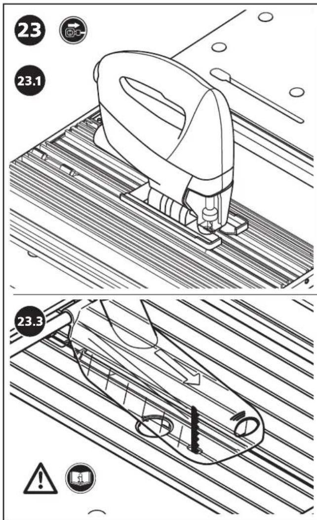
Align the jigsaw on the machine plate in such a way that the saw blade runs in the centre of the saw opening (Fig. 23.1). Install the jigsaw with four side stops and four claws as illustrated (Fig. 23.2). Close and lock the machine plate as shown in Fig. 17. Attach the switch clamp to the switch on the jigsaw and connect the appliance inlet to the safety switch. Always use the protective hood when operating the jigsaw (Fig. 23.3).

USE AS A WORKBENCH
The MASTER cut 1500 is equipped with 4 plastic clamping claws. They can be used to clamp workpieces flexibly and safely (Fig 24).
GB
ADJUSTING THE MACHINE PLATE
The height of the machine plate in the worktop was set in the factory to ensure that the workpiece glides smoothly over the worktop and machine plate area. The height of the machine plate can be adjusted, if necessary. Loosen the six lock nuts. Align the height of the machine plate using the six adjusting screws until it is flush with the worktop and then tighten the lock nuts again. Before starting work, always check that the six lock nuts are fastened tightly. Also check that the screws and lock nuts on both holders for engaging the machine plate are always fastened tightly (Fig. 25).

SPECIAL ACCESSORIES FOR THE MASTER cut 1500
TWO EXTRA ATTACHABLE RIVING KNIVES, ART. NO. 6930000 AND 6904000 DESIGNED
FOR HAND-HELD CIRCULAR SAWS WITHOUT A RIVING KNIFE
CAUTION: The special accessories described here are only compatible with the MASTER cut 1500.
NOTE: The following section describes how this special accessory functions and is operated, and an illustration is included on page 24.
INTENDED USE
The two riving knives enable the operation of hand-held circular saws that have no riving knife.
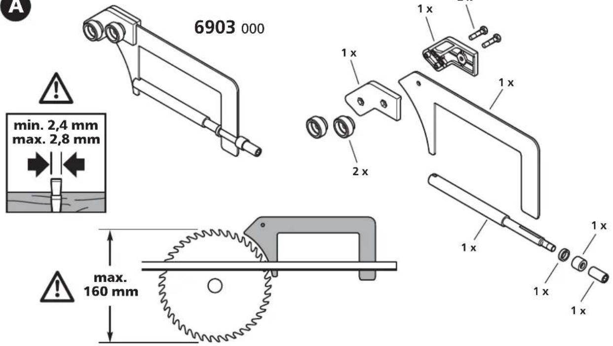
Riving knife 6903000 is designed for hand-held circular saws with circular saw blades that have a maximum diameter of 160 mm and a cutting width between 2.4 mm and 2.8 mm.
Riving knife 6904000 is designed for operating hand-held circular saws with saw blades that have a maximum diameter of 200 mm, a cutting width between 2.4 mm and 2.8 mm and a maximum cutting depth of 66 mm.
CAUTION: Before using the special accessories, always read the general safety instructions, the safety instructions for hand-held circular saws and the original instruction manual accompanying the hand-held circular saw without a riving knife.

RIVING KNIVES ART. NO. 6903000 AND 6904000
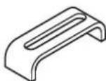
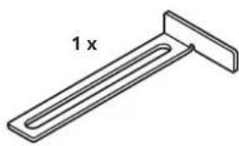
Riving knife 6903000 includes the following components: 1x riving knife (for a max. circular saw blade diameter of 160 mm), 1x riving knife holder (long version), 1x setting gauge (Fig. A).
Riving knife 6904000 includes the following components: 1x riving knife (for a max. circular saw blade diameter of 200 mm), 1x riving knife holder (short version), 1x setting gauge (Fig. B).
CAUTION: The following section describes how the riving knife (Art. No. 6903000) for hand-held circular saws with a max. saw blade diameter of 160 mm is assembled and functions.
The riving knife (Art. No. 6904000) for hand-held circular saws with a max. saw blade diameter of 200 mm is assembled and functions in the same way. However, it is possible to machine workpieces with a max. height of 60 mm using this riving knife.
ATTACHING RIVING KNIVES
Open the machine plate as shown in Fig. 16 (Fig. C.1). Assemble the locating bolt with the fixing parts. Assemble the components loosely (Fig. C.2). Close the machine plate (Fig. C.3). Insert the riving knife approx. 2cm into the groove on the locating bolt from above. Make sure that the riving knife is inserted in the direction of the arrow up to the stop on the machine plate as illustrated (= vertical direction). Tighten the Allen screw (Fig. C.4, C.5). Open the machine plate again (Fig. C.6).
ASSEMBLY OF THE HAND-HELD CIRCULAR SAW
Retract the protective pendulum hood on the hand-held circular saw and position the machine centrally over the saw gap. Release the cutting depth lock on the circular saw and set the machine to the maximum cutting depth. Tighten the cutting depth lock again.
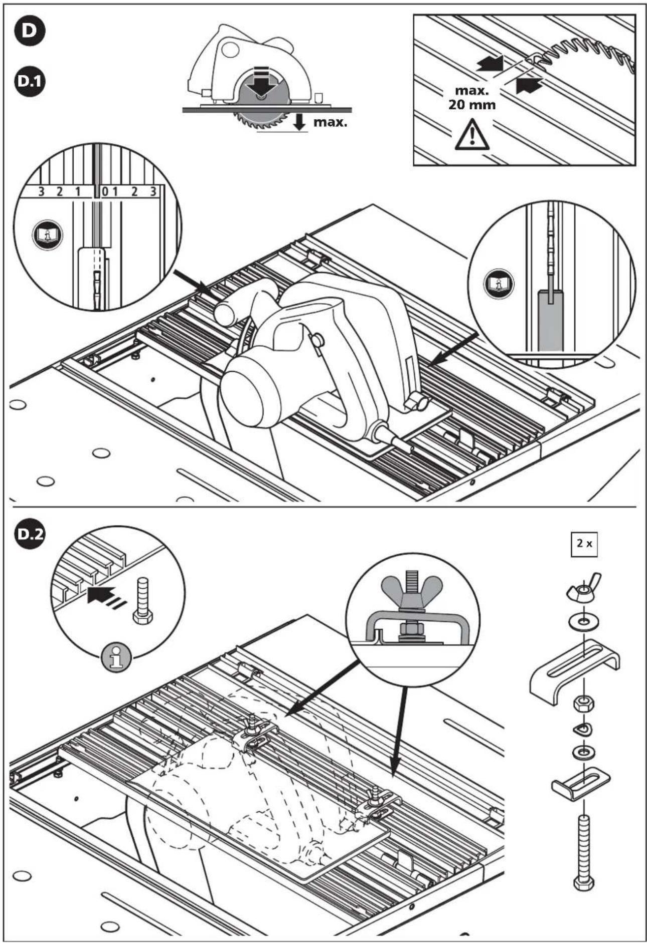
CAUTION: Check the distance between the foremost tooth on the saw blade to the front edge of the saw gap. This distance must be less than 20 mm.
Align the front end of the hand-held circular saw with the 0 mark on the base plate of the hand-held circular saw and the two auxiliary marking lines on the machine plate. At the rear end of the handheld circular saw, align the saw blade centrally in relation to the riving knife (Fig. D.1). Note: The best place to check whether the machine is aligned correctly is behind the riving knife in the direction of the circular saw blade because the saw blade is thicker than the riving knife. After aligning the hand-held circular saw, attach the two side stops so that their surfaces are in full contact with the machine's base plate. Then attach the two clamping claws (Fig. D.2).
CAUTION: Make sure that the saw blade is aligned centrally in relation to the riving knife, otherwise the hand-held circular saw must be realigned.
Secure another side of the base plate. Install the angle bracket with two side stops first. Make sure they are in full contact with the base plate. In the same way, install an angle bracket with two side stops on the opposite side. Attach the two clamping claws (Fig. D.3). The two clamping claws must be installed as close to the longer side of the base plate as possible. Note: Refer to pages 13 - 15 for other attachment options on a variety of base plates.
Adjust the safety distance between the riving knife and circular saw blade using the setting gauge.
Close the machine plate (Fig. E.1). Fit the individual parts to the riving knife as shown in the illustration (Fig. E.2). Tighten the screw and the knurled nut connected to the riving knife and loosely tighten the screw and knurled nut in the front of the housing (Fig. E.3). Loosen the riving knife fastening using the Allen wrench (Fig. E.4). Slide down the riving knife vertically in relation to the circular saw blade (Fig. E.5). Slide down the riving knife until at least one circular saw blade tooth reaches the housing of the setting gauge (detailed view E.6). Now tighten the front knurled nut (Fig. E.6). When the Allen screw is tightened, the safety distance between the circular saw blade and the riving knife is adjusted to max. 5 mm (Fig. E.7). Then unscrew the setting gauge from the riving knife (Fig. E.8).
CAUTION: Make sure that the saw blade is aligned centrally in relation to the riving knife (detailed view in Fig. E.8) and that the max. safety distance of 5 mm between the circular saw blade and riving knife is maintained (detailed view in Fig. E.6), otherwise the hand-held circular saw must be realigned.
CAUTION: Before starting work, always check that the riving knife and fixing parts are fastened tightly!
GB
Lock the machine plate as shown in Fig. 17. The table is now ready for stationary sawing, please also read the section on stationary sawing with the hand-held circular saw.
Cutting depth adjustment
If the cutting depth of the hand held circular saw is changed, the height of the riving knife must also be adjusted to guarantee the max. 5 mm safety distance to the circular saw blade. First loosen the riving knife using the Allen wrench. Then set the hand-held circular saw to the required cutting depth. Tighten the cutting depth lock again. Attach and position the setting gauge together with the riving knife as illustrated in Fig. E.1 to E.8.
Vertical mitre cuts
The hand-held circular saw must be realigned for vertical mitre cuts. Set the required mitre angle on the hand-held circular saw. Retract the protective pendulum hood on the hand-held circular saw and position the machine centrally over the saw gap. Release the cutting depth lock on the circular saw and set the machine to the maximum cutting depth. Tighten the cutting depth lock again (Fig. F.1, F.2). Loosen the Allen key and turn the riving knife until it is positioned exactly central in relation to the circular saw blade (Fig. F.3).
CAUTION: Check the distance between the foremost tooth on the saw blade to the front edge of the saw gap. This distance must be less than 20 mm (Fig. F.4).
Tighten the Allen screw (Fig. F.5).
CAUTION: Align the saw blade parallel in the saw gap while ensuring that the circular saw blade is always positioned centrally in relation to the riving knife.
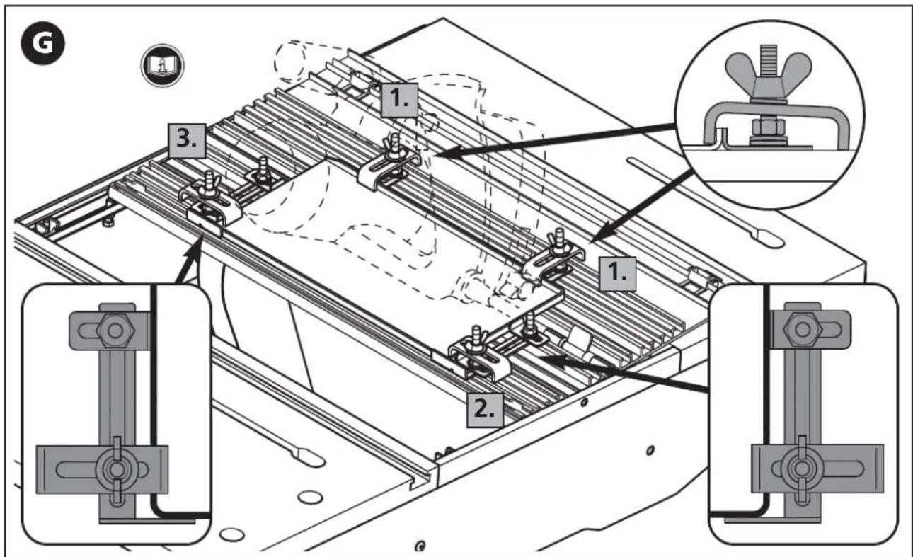
Attach the two side stops so that their surfaces are in full contact with the machine's base plate. Then attach the two clamping claws. Secure another side of the base plate. Install the angle bracket with two side stops first. Make sure they are in full contact with the base plate. In the same way, install an angle bracket with two side stops on the opposite side. Attach the two clamping claws. The two clamping claws must be installed as close to the longer side of the base plate as possible (Fig. G).
Adjust the safety distance between the riving knife and circular saw blade using the setting gauge.
Close the machine plate (Fig. H.1). Fit the individual parts to the riving knife as shown in the illustration (Fig. H.2). Tighten the screw and the knurled nut connected to the riving knife and loosely tighten the screw and knurled nut in the front of the housing (Fig. H.3). Loosen the riving knife fastening using the Allen wrench (Fig. H.4). Slide the riving knife towards the circular saw blade at the same angle as the saw blade (Fig. H.5). Slide down the riving knife until at least one circular saw blade tooth reaches the housing of the setting gauge (detailed view H.6). Now tighten the front knurled nut (Fig. H.6). When the Allen screw is tightened, the safety distance between the circular saw blade and the riving knife is adjusted to max. 5 mm (Fig. H.7). Unscrew the setting gauge from the riving knife again. Lock the machine plate as shown in Fig. 17 and check once again that the saw blade rotates freely (Fig. I).
CAUTION: Make sure that the saw blade is aligned centrally in relation to the riving knife (detailed view in Fig. I) and that the max. safety distance of 5 mm between the circular saw blade and riving knife is maintained (detailed view in Fig. H.6), otherwise the hand-held circular saw must be realigned.
CAUTION: Before starting work, always check that the riving knife and fixing parts are fastened tightly!
The table is now ready for stationary sawing, please also read the section on stationary sawing with the hand-held circular saw.

Warranty
Dear hobbyist!
You have purchased a high-quality wolfcraft ^® appliance, which we know you will enjoy using. wolfcraft ^® appliances are built to high technical standards, and undergo intensive development and test phases before leaving the factory. Constant controls and regular tests during their manufacture, ensure a high quality standard. Sound technical developments, and reliable quality controls warrant for the right choice of appliance.
We provide a warranty of 10 years from the day of purchase on the wolfcraft® product you acquired, provided it is exclusively used for DIY purposes. The warranty only covers damage to the item purchased, and only such damage that can be attributed to faulty material und poor workmanship. The warranty does not cover defects and damage that must be attributed to improper use or insufficient maintenance. Nor does the warranty cover the usual wear and tear as well as defects and damage, of which the customer has been aware when purchasing the equipment.
Warranty claims can only be asserted by producing the invoice or the till receipt.
The warranty granted by wolfcraft* does not in any way restrict your statutory consumer rights (i.e. contract performance, withdrawal from the contract, price reduction, claims for damages or reimbursement of expenses).
Declaration of Conformity pursuant to Directive 2006/42/EC on Machinery, Annex II A
wolfcraft GmbH in D-56746 Kempenich, Wolff-Str. 1, hereby declares that this product (MASTER cut 1500) conforms to Directive 2006/42/EC on Machinery. TUEV Rheinland LGA Products GmbH, Tillystrasse 2, 90431 Nürnberg. BM: 60087567 0001 Conformity with the following standards: DIN EN 60745-1, DIN EN 60745-2-5, DIN EN 60745-2-11
Person authorized to sign the Declaration of Conformity and to compile the technical documentation. (Management/Technology/Logistics; wolfcraft GmbH)
F
INTRODUCTION
MONTAGE DU COIN DE FENDAGE
SPESIALTILBEH∅R FOR MASTER cut 1500
TO EKSTRA AVTAKBARE KL∅YVEKNIVER, DELENR. 6930000 OG 6904000, DESIGNET FOR HÅNDHOLDTE SIRKELSAGER UTEN KL∅YVEKNIV
PŘÍPRAVA K UPNUTÍ STROJE
(Conducerea/logistică/dep.tehnic; wolfcraft GmbH)
BG
УВОД
(correspondence in English)
E
Technical and Commercial Company
12, Papastratou & Asklipiou, Str.
185 45 Piraeus
Telefon: 0030 - 2104136155
Telefax: 0030-2104137692
info@mavrofidopoulos.gr
HR
Manal d.o.o.
Velimira Skorpika 1 a
10090 Zagreb
Telefon: 00385 - 1 - 3466400
Telefax: 00385-1-3466412
manal@manal.hr
RO MD
Steinel Distribution s.r.l.
Parc Industrial Metrom Str. Carpatilor nr. 60
RO - 500269 Brasov
Telefon: +40 (0) 268 530 000
Telefax: +40 (0) 268 531 111
info@steinel.ro
AL
SLAV GmbH
Tzar Osvoboditel 331
9000 Varna
Telefon: 00 359 - 52 - 739072
Telefax: 00 359 - 52 - 739073
office@wolfcraft.bg
SRS MN
Mi-lumen d.o.o.
Dositejeva 176
36000 Kraljevo
Telefon: 00381-36-231081
Telefax: 00381-36-312867
milumen@tron-inter.net
ALS
EIG Sh.p.k.
Frigoriferi Metalik
Rr. Siri Kora
4000 Tirana
Telefon: 00355 4 250125
Telefax: 00355 4 259501
info@extra.al
(18)
Centroinstrument
12351 Moskau
Molodogwardeskaja Ul. 61
Tel.: (495) 730 - 80 - 70
Fax: (495) 730 - 80 - 75
Centroinstrument-Ural
① We reserve the right for technical modifications