
TYST58PF20 - TV PANASONIC - Free user manual and instructions
Find the device manual for free TYST58PF20 PANASONIC in PDF.

| Brand | Panasonic |
| Model | TYST58PF20 |
| Product type | Mobile pedestal for plasma screen |
| Compatible screens | Panasonic plasma screens from 42 to 58 inches |
| Shelf height | Adjustable to about 35 cm or 50 cm from the floor |
| Maximum shelf capacity | 20 kg |
| Casters | 2 casters with brake |
| Materials | Steel, plastic |
| Pedestal weight | Not specified, designed to support a screen up to 58 inches |
| Power supply | None (passive support) |
| Installation | By a qualified technician recommended |
| Safety | Anti-tip measures mandatory, do not exceed 20 kg on the shelf, do not block ventilation |
| Maintenance and cleaning | Wipe with a soft dry cloth. For stains, use a diluted neutral detergent then dry. Do not use gasoline, thinner or furniture wax. |
| Included parts | Base unit with casters, base joint, left/right uprights, shelf, shelf brackets, screen brackets, screws, hex key, cable ties, stickers |
| Reparability | Repairs must be entrusted to a qualified technician |
| User manual | Available in several languages at notice-facile.com |
Frequently Asked Questions - TYST58PF20 PANASONIC
User questions about TYST58PF20 PANASONIC
0 question about this device. Answer the ones you know or ask your own.
Ask a new question about this device
Download the instructions for your TV in PDF format for free! Find your manual TYST58PF20 - PANASONIC and take your electronic device back in hand. On this page are published all the documents necessary for the use of your device. TYST58PF20 by PANASONIC.
USER MANUAL TYST58PF20 PANASONIC
natural_image
Line drawing of a mechanical lifting device with wheels and a flat base (no text or symbols)Model No.
TY-ST58PF20
| 組み立て設置工事説明書プラズマディスプレイ用移動式スタンド | 日本語 |
| Installation InstructionsMobile stand for Plasma Display | Italy |
| InstallationsanleitungMobiler Ständer für Plasmadisplay | Spain |
| InstallatiehandleidingMobiele standaard voor plasmascherm | Italy |
| Istruzioni per l’installazioneSupporto mobile per lo schermo al plasma | Italy |
| Manuel d’installationPied mobile pour l’écran plasma | |
| Instrucciones de instalaciónPedestal móvil para la pantalla de plasma | |
| InstallationsanvinsningarFlyttbart stativ för Bred plasmaskärmen | |
| MonteringsvejledningRullebord til plasmaskærm | |
| Инструкция по установкеМобильная подставка плазменного дисплея | |
| Орнату нускауларыПлазмалык дисплейдің жылжымалы тіреуіші | Казахский |
| Інструкції з встановленняПереносна підставка плазмового дисплея | Казахский |
| 安裝説明書電漿顯示器移動式台架 | 中文 |
| 組み立て設置工事前に、この説明書とプラズマディスプレイ本体の取扱説明書をよくお読みのうえ、正しい取り付け設置を行ってください。(移動やメンテナンスの際に必要になる場合がありますので、説明書を保存していただきますようお願いいたします。) | |
| Before commencing work, carefully read these Instructions and the Manual for the plasma display to ensure that fitting is performed correctly.(Please keep these instructions. You may need them when maintaining or moving.) | |
| Vor der Ausführung lesen Sie bitte diese Anleitung und die Bedienungsanleitung für das Plasmadisplay sorgfältig durch, damit die Anbringung richtig ausgeführt wird.(Bitte bewahren Sie diese Anleitung auf. Sie kann bei der Wartung oder der erneuten Anbringung des sockels benötigt werden.) | |
| Lees deze installatiehandleiding en de bedieningshandleiding voor het plasmascherm zorgvuldig door voordat u begint, zodat de montagewerkzaamheden op de juiste wijze worden uitgevoerd.(Bewaar deze handleiding. U hebt de handleiding weer nodig bij onderhoud en verplaatsing.) | |
| Prima di iniziare il montaggio leggere attentamente queste istruzioni ed il manuale dello schermo al plasma per poter procedere al montaggio in modo corretto.(Conservare poi queste istruzioni che si renderanno necessarie per la manutenzione e l'eventuale spostamento della staffa.) | Italiano Frabegaris Espanol Svenska Dagisk Hrdn Kachu語 |
| Avant de commencer le travail, lisez attentivement ces instructions ainsi que le mode d'emploi de l'écran plasma de manière à réaliser un montage convenable.(Conservez soigneusement les présentes instructions. Vous pouvez en avoir besoin pour effectuer un entretien ou si vous désirez déplacer l'applique.) | |
| Antes de empezar el trabajo, lea atentamente estas instrucciones y el manual de la pantalla de plasma para asegurar una instalación correcta.(Guarde estas instrucciones. Podrá necesitarlas cuando haga trabajos de mantenimiento o mueva el soporte.) | |
| Innan arbetet påbörjas ska du noga läsa dessa anvisningar och bruksanvisningen som medföljer plasmaskärmen för att försäkra att arbetet utförs på rätt sätt.(Bevara dessa anvisningar. Du kan behöva anlita dem på nytt för underhåll eller flyttning av hållaren.) | |
| Før arbejdet påbegyndes, skal du omhyggeligt læse disse instruktioner og betjeningsvejledningen til plasmaskærmen for at sikre at opsætningsarbejdet udföres korrekt.(Gen disse instruktioner. Du kan få brug for dem ved vedligeholdelse, eller hvis ophænget skal flyttes.) | |
| Перед проведением работ внимательно прочитайте эту Инструкцию и Руководство для плазменного дисплея, чтобы убедиться в том, что установка выполняется правильно.(Сохраните, пожалуйста, эту инструкцию. Она может Вам понадобиться для технического обслуживания или перемещения.) | |
| Жумысты бастаудан эуелі, орнатудың дұрыс орындалуын қамтамасыз ету үшін, осы Нұсқаулар мен плазмалық теледидардың нұсқаулығын мұқият окып шығыңыз.(Осы нұсқаулықтарды сақтап қойыңыз. Ол сізге қызмет көрсеткен немесе орнын ауыстырган кезде керек болуы мүмкін.) | Казахский |
| Перед початком робіт уважно прочитайте ці інструкції та інструкції з експлуатації плазмового дисплея, аби забезпечити правильний монтаж.(Збережіть ці інструкції, оскільки вони можуть знадобитись Вам, коли виникне необхідність у технічному обслуговуванні або встановленні дисплея в іншому місці.) | Українська |
| 安裝前,請仔細閱讀本說明及電漿顯示器的用戶手冊,以確保正確安裝。(請妥善保留本說明。在維護或移動時您可能需要使用本說明。) | 中文 |
安全上のご注意
必ずお守りください
natural_image
Line drawing of a flatbed rectangular object with wheels and a side-mounted base (no text or symbols)② ベースジョイント(1 個)
natural_image
Simple line drawing of a rectangular metal profile (no text or symbols)natural_image
Technical line drawing of a mechanical bracket or support structure (no text or symbols)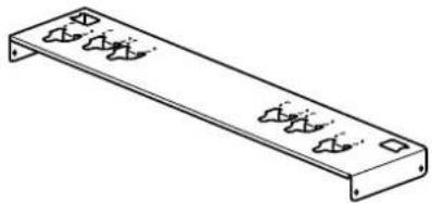
natural_image
Technical line drawing of a rectangular metal plate with multiple side slots and mounting holes (no text or symbols)付属部品
natural_image
Technical line drawing of a mechanical assembly with mounting brackets and structural supports (no text or symbols)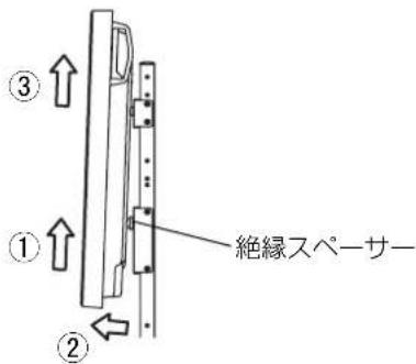
Installation and removal should only be carried out by a qualified technician.
- If the stand is not installed correctly, the Plasma display may fall over and become damaged, and personal injury may result.
Do not disassemble or modify the mobile stand.
- Otherwise the unit may fall over and become damaged, and personal injury may result.
Set up in a location with little vibration that can support the weight of the unit.
- Otherwise the unit may fall over or down, and personal injury may result.
Ensure that the installation location is strong enough to support long-term use.
- If its strength becomes insufficient over the course of long-term use, the display may topple over, possibly causing injury.
CAUTION
Do not use any plasma displays other than those given in the catalogue.
- Otherwise the unit may fall over and become damaged, and personal injury may result.
Do not place weight of over 20 kg (44.09 lbs.) on the shelf plate.
- Otherwise the unit may fall over or down, and personal injury may result.
Do not use the mobile stand if it becomes warped or physically damaged.
- Otherwise the unit may fall over and become damaged, and personal injury may result.
Do not lubricate the casters.
- The casters may crack or became damaged, and the display may fall down and became damaged, and personal injury may result.
Do not climb on or hang from the plasma display or mobile stand.
- Be particularly careful that young children obey this caution. Otherwise the unit may fall over and become damaged, and personal injury may result.
Do not block the ventilation holes. Do not block the space between the bottom of plasma display and the floor when using the mobile stand.
- Otherwise heat may build up inside and cause a fire.
Take steps to prevent toppling.
- Earthquakes or children climbing up or onto the display may cause the display to topple over, possibly resulting in injury.
Secure at least 10 cm (3.9 inches) of space at the top, bottom, left, and right of the plasma display.
Also secure at least 7 cm (2.8 inches) of space at the back.
- Failing to do so may result in a fire.
Keep the unit away from direct sunlight and heating equipment.
- Failure to do so may result in warping, deformation, or degradation of materials, and a loss of strength that may cause the equipment to fall over or break and cause injury.
The work of fitting or removing the plasma display must be performed by at least two people.
- The plasma display may fall and cause injury.
During assembly and setup work, make sure that all screws are securely tightened.
- If assembly is not performed correctly, the pedestal will not be able to support the weight of the display. This may result in the display falling over and becoming damaged, which may result in personal injury.
Set up on a stable, level surface.
- Otherwise the unit may fall over and become damaged, and personal injury may result.
For installation, use the special-purpose constituent parts.
- Otherwise, the plasma display may fall off the mobile stand and be damaged, possibly causing injury.
Unlock the casters when moving the display.
- Otherwise the unit may fall over and become damaged, and personal injury may result.
Dispose of the product when it is no longer going to be used.
- Otherwise the unit may fall over and become damaged, and personal injury may result.
Requests regarding handling
1) Exercise care when selecting the location for the display because it may discolor or deform due to light or heat if it is placed where it is exposed to direct sunlight, or near a heater.
2) For cleaning, wipe the display using a soft dry cloth (made of cotton or flannel). If the unit is extremely soiled, first wipe off soiling with a neutral detergent diluted in water, and then wipe with a dry cloth. Do not use cleaners such as benzene, thinner or furniture wax because they may cause paint peeling. (For information on cleaning the plasma display, see the plasma display's instruction manual. If using a chemically-treated cloth, follow the instructions supplied with the cloth.)
3) Do not affix adhesive tape or stickers to the product. Doing so may dirty the surface of the mobile stand. Do not allow long-term contact with rubber, vinyl products or the like. (Doing so will cause deterioration.)
4) The panel of the plasma display is glass. Do not subject it to a strong force or impact.
Precautions for mobile stand assembly and setup work
- To ensure correct plasma display performance and prevent trouble, do not fit at any of the following locations.
- Near sprinklers or fire/smoke detectors
- Where there is a risk of exposure to vibration or impact
- Near high-voltage wires or dynamic power supplies
- Near sources of magnetism, heat, water vapor or soot
- Locations exposed to air blown from heating equipment
- Where droplets of condensation from an air conditioner or other unit may form
- For the plasma display power supply plug, use a power supply outlet that can be reached easily.
- Ensure good air flow so that the ambient temperature does not exceed 40 °C (104 °F). Failure to do this may cause heat to build up inside the plasma display, resulting in malfunction.
- Fit so there is no contact between the attachment bolts or power cord and any metal inside the wall.
- Spread a soft blanket or cloth over the floor so that the stand and floor will not be marked or scratched during the assembly and installation work.
- Perform the assembly and installation work on a flat and level surface, and follow the assembly and installation work instructions.
- When screwing down the parts, ensure that the screws are neither insufficiently tightened nor over tightened.
- Take sufficient care to ensure safety around you when performing the assembly and installation work or while moving about during the course of the work.
- Be sure to read and observe the "Safety precautions".
This stand is intended for only Panasonic plasma display models (See page 121). Use with other apparatus is capable of resulting in instability causing possible injury.
PROFESSIONAL INSTALLATION IS REQUIRED. PANASONIC DISCLAIMS ANY PROPERTY DAMAGE AND/OR SERIOUS INJURY, INCLUDING DEATH RESULTING FROM IMPROPER INSTALLATION OR INCORRECT HANDLING.
Main parts
Check that all the parts are accounted for and present in their designated quantities.
1 Base unit with casters (2)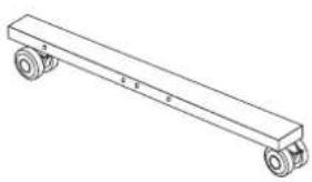 | 2 Base joint (1)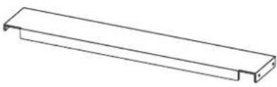 | 3 Support column (left/right)(One for each side)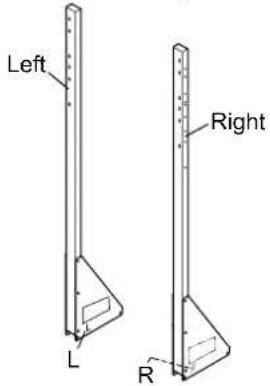 | |
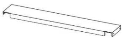
4 Shelf plate (1)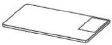 | 5 Bracket for shelf plate (2) | ||
6 Top bracket for plasma display (1)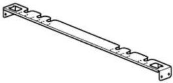 | 7 Bottom bracket for plasma display (1)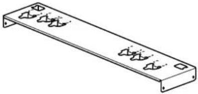 | ||
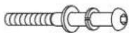
Accessory parts
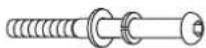
Hexagon socket cap button bolt (M8 × 65)Spring washer/Flat washerCap nut with flange (M8)(Four each)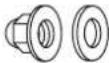 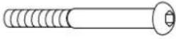 | Hexagon socket cap button bolt (M8 × 70)Spring washer/Flat washerCap nut with flange (M8)(Six each)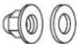 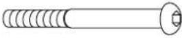 | Allen headcountersunk screwDished toothed washerInsulation spacer(Four each)  | ||
Screw for attaching bracket for shelf plate (M5 × 18) (4)Screw for attaching bracket for plasma display (M5 × 18) (8)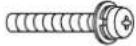 | Screw for securing unit(M4 × 16) (2)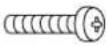 | Wood screw (4) | ||
Clamper (5)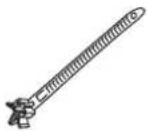 | Cover stickers(48 (2 sheets)) | Allen wrench (included tool) (1)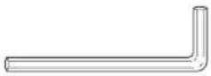 | ||
[The images shown in this manual are for illustrative purpose only.]
1. Assembling of the stand
When assembling, make so the caps nut of the hexagon socket cap button bolts are on the inside of the stand. Length of hexagon socket cap button bolts is 65 and 70 mm (2.6 and 2.8 inches). Be careful not to use the wrong bolts.
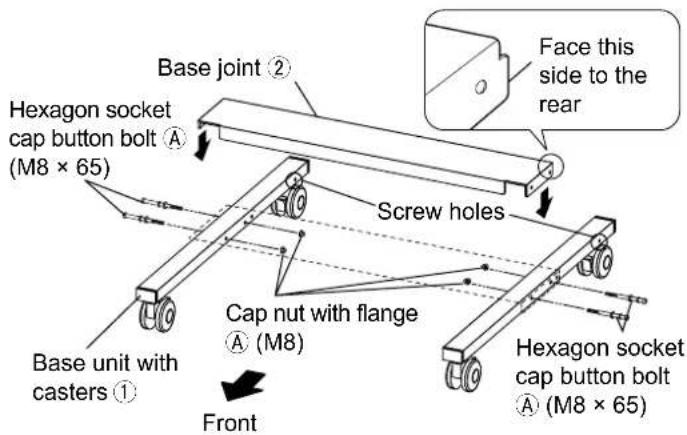
1. Assembling the stand base
Preparing hexagon socket cap button bolts Ⓐ
Ready four sets by passing spring washers and flat washers over hexagon socket cap button bolts (M8 × 65).
Face screw holes of base unit with caster to the rear and align with base joint ② as shown in the figure on the right, and fasten with the four readied hexagon socket cap button bolts A (M8 × 65) and cap nuts with flanges A.
(Tightening torque: 8 to 10 N•m)
2. Attaching the support columns
Preparing hexagon socket cap button bolts Ⓑ
Ready six sets by passing spring washers and flat washers over hexagon socket cap button bolts (M8 × 70).
Face the "L" and "R" marks of support columns (left/right) ③ to the inside, and insert the bottom plates into the back side of the stand base from above. Temporarily secure support columns (left/right) ③ with the readied four hexagon socket cap button bolts B (M8 × 70) and cap nuts with flanges B.
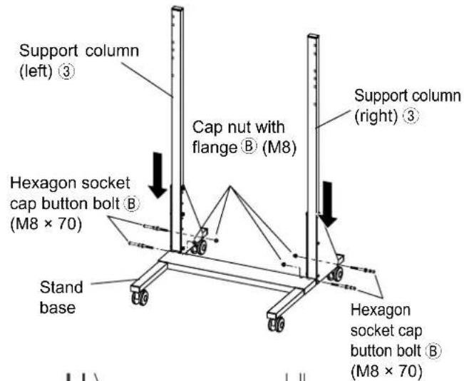
3. Perpendicular adjustment and fixing of the support columns
Adjust the support columns (left/right) so that they are perpendicular to the stand base. Tightly fasten the four hexagon socket cap button bolts that temporarily fixed the support columns.
(Tightening torque: 8 to 10 N·m)
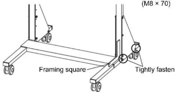
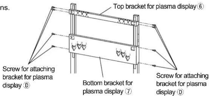
4. Attachment of brackets for plasma display (top/bottom)
- The attachment position differs according to the size of the plasma display to be set up. (The figure on the right covers setting up a 50-inch TV.)
① Hang the tabs of the top bracket for plasma display ⑥ to the cutouts for temporarily holding the bracket for plasma display located on the front of the left and right support columns. Fasten with four screws for attaching bracket for plasma display ⑭ from the side.
(Tightening torque: 2 to 3 N·m)
* See the figure on the right for attachment positions.
② Hang the tabs of the bottom bracket for plasma display ⑦ to the cutouts for temporarily holding the bracket for plasma display located on the front of the left and right support columns. Fasten with four screws for attaching bracket for plasma display ⑧ from the side.
(Tightening torque: 2 to 3 N·m)
* See the figure on the right for attachment positions.
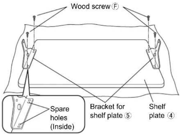
5. Preparation of the shelf plate
Face the unpainted side (back side) of the shelf plate ④ upward and place it on a soft cloth or the like. Align the positioning holes of the shelf plate with the bracket protrusions to position the two brackets for shelf plate ⑤, and attach them with four wood screws ⑥ through the outside holes.
(Tightening torque: 1 to 1.2 N·m)
* Do not excessively fasten the wood screws to prevent stripping screw holes. If a screw hole is stripped, use spare holes.
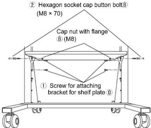
6. Shelf plate fitting
- Shelf plate fitting position can be adjusted for the top of the shelf plate to be either approx. 35 or 50 cm (13.8 or 19.7 inches) from the floor.
The figure shows an example of fitting to the upper level (50 cm [19.7 inches] from floor).
① Turn so the caution label of the readied shelf plate is on the back right, align the bracket for shelf plate ⑤ screw holes and the support column ③ inside right and left screw holes, and fasten with four screws for fitting bracket for shelf plate D.
(Tightening torque: 2 to 3 N·m)
② Fasten from the left and right of the outside of the support column with the two readied hexagon socket cap button bolts Ⓑ and cap nuts with flanges Ⓑ.
(Tightening torque: 8 to 10 N·m)
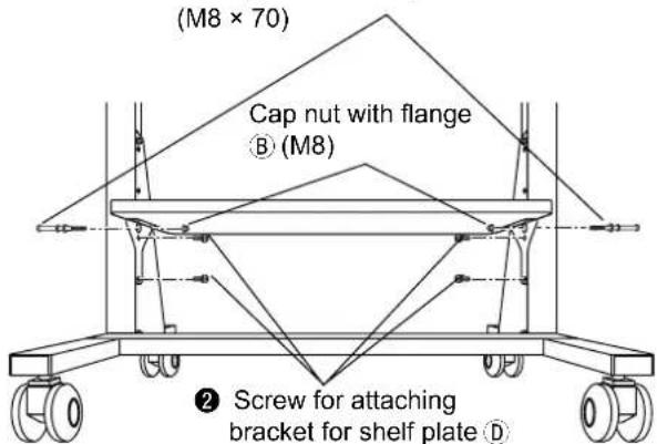
If fitting at lower level (35 cm [13.8 inches] from floor)
① Fasten with two hexagon socket cap button bolts and cap nuts with flanges ⑧ through the bolt holes on the right and left sides of the upper level (50 cm [19.7 inches] from floor).
② Remove the two hexagon socket cap button bolts on the left and right sides at the lower level position.
③ Then fit the same way as in procedures ① and ② for fitting the upper level.
To change shelf plate height
- Changing the shelf plate height after setting up the plasma display will make the stand unstable. Remove the plasma display from the mobile stand.
① Hexagon socket cap button bolt®
2. Preparing the plasma display
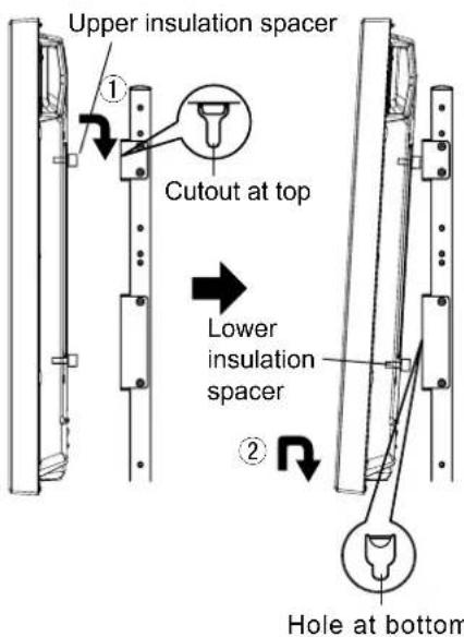
Attaching the insulation spacers
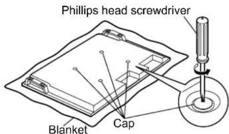
① Place the front surface of the plasma display on a clean cloth that has no dirt or foreign objects on it, and follow the procedure below.
If the plasma display has any protruding parts, take care not to scratch or damage them.
② Remove the four caps from the plasma display using a Phillips head screwdriver.
Note
Keep the caps that were removed in a safe place.
(They will be required if you use the pedestal.)
③ Using the supplied Allen wrench ①, attach accessory parts ⑥ (four Allen head countersunk screws, dished toothed washers, and insulation spacers) at the locations where the caps were removed as shown in the figure on the right.
(Tightening torque: 3 to 4 N·m)
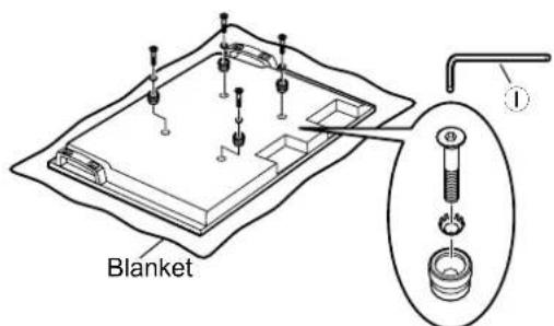
Accessory parts ©
3. Fitting to the stand
Note
Before fitting the plasma display, make sure to lock the casters.
Locking and unlocking the casters
Caster locked
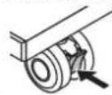
Push the bottom of the lever
Caster unlocked
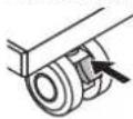
Push the top of the lever
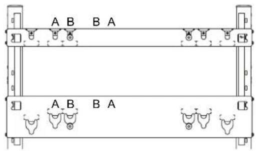
Mark A: 58-inch
Mark B: 42/50-inch
No mark: Spare
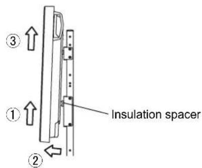
1. Fitting plasma display
① Engage the upper insulation spacers of the plasma display with the cutouts at the top of the mobile stand, and slowly lower the plasma display into place.
② While lifting the plasma display slightly, insert the bottom insulation spacers into the holes at the lower end of the mobile stand, and then lower the plasma display straight down into place.
CAUTION
If the plasma display is lifted too much, it will fall down and personal injury may result.
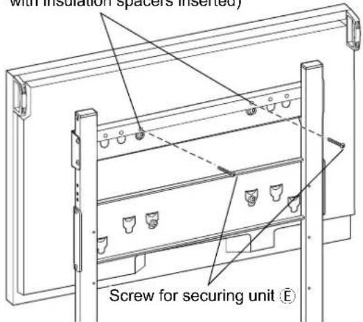
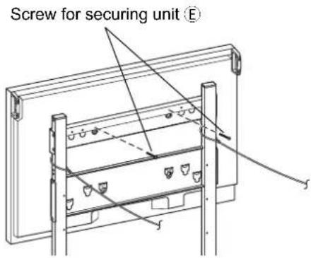
2. Fixing of the plasma display
Firmly tighten the two screws for securing unit in the holes of the top bracket for plasma display ⑥. (Tightening torque: 1.5 to 2 N·m)
Note
Make sure to fit the screws for securing unit Ⓔ on the left and right to prevent the plasma display from coming off.
Holes for screws for securing unit (Use screw holes above cutouts with insulation spacers inserted)
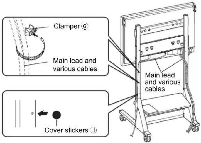
4. Setup and wiring of connected devices
① Insert the five clampers in any of the six clamper attachment holes on the back side of the left and right support columns at positions that make wiring easy. Wire as shown in the figure.
② Place cover stickers in unused spare holes on the sides and back of the support columns and other locations.
Note
Do not bundle the connection cables and main lead together.
5. Preventing falling over
In order to prevent the unit from falling over, fix the left and right support columns using strong cords or wires passed between the top and bottom brackets for plasma display, and connect them without slack to sturdy pillars or walls. (Use commercially available cord or wire to prevent falling over.) The distance between the pillar or wall and the rear of the plasma display must be 1 m (39.4 inches) or less.
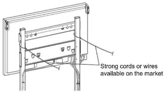
[For safety reasons, always use the overturn/fall prevention accessories]
The equipment may overturn in the event of an earthquake etc. Therefore, always use the overturn/fall prevention accessories.
* The details in this section indicate how to reduce any damage or injury caused by this equipment overturning or falling due to an earthquake. However, there is no guarantee that the overturn/fall prevention accessories will be effective in all earthquake situations.
Removing the plasma display
① Remove the two screws for securing unit on the back of the top bracket for plasma display on the mobile stand.
② Remove the cord or wire for preventing the unit from falling over.
③ Disconnect the power cord and the wires connecting the plasma display to the other units.
④ While lifting the bottom part of the plasma display, pull the plasma display toward you.
⑤ After the bottom insulation spacers have been removed, continue lifting up the plasma display and remove it.
Warnung
natural_image
Technical line drawing of a mechanical assembly with mounting brackets and structural elements (no text or symbols)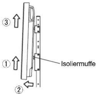
Waarschuwing
Geen marketing: reserve
natural_image
Technical line drawing of a mechanical assembly with mounting brackets and structural supports (no text or symbols)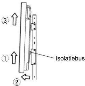
Avvertenza
natural_image
Technical line drawing of a mechanical assembly with mounting brackets and structural elements (no text or symbols)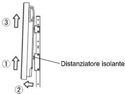
natural_image
Technical line drawing of a mechanical assembly with mounting brackets and structural supports (no text or symbols)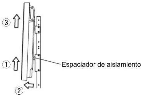
Ingen marketing: Reserv
natural_image
Technical line drawing of a mechanical assembly with mounting brackets and structural elements (no text or symbols)
ПРЕДУПРЕЖДЕНИЕ
natural_image
Technical line drawing of a mechanical assembly with mounting brackets and structural supports (no text or symbols)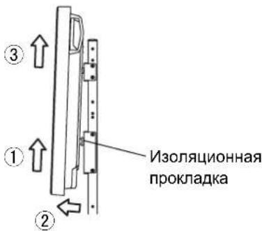
natural_image
Technical line drawing of a mechanical assembly with mounting brackets and structural elements (no text or symbols)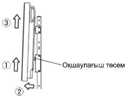
ПОПЕРЕДЖЕННЯ
natural_image
Technical line drawing of a mechanical assembly with mounting brackets and structural supports (no text or symbols)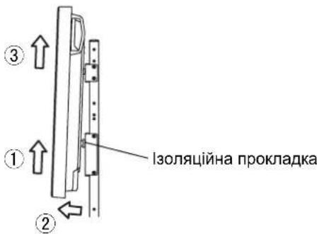
natural_image
Technical line drawing of a mechanical assembly with mounting brackets and structural supports (no text or symbols)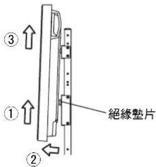
プラズマディスプレイ用移動式スタンド Mobile stand for Plasma Display Mobiler Ständer für Plasmadisplay Mobiele standaard voor plasmascherm Supporto mobile per lo schermo al plasma Pied mobile pour l'écran plasma Pedestal móvil para la pantalla de plasma Flyttbart stativ för Bred plasmaskärmen Rullebord til plasmaskærm Мобильная подставка плазменного дисплея Плазмалык дисплейдің жылжымалы тіреуіші Переносна підставка плазмового дисплея 電漿顯示器移動式台架
外形寸法図 External dimensions drawing Abbildung mit externen Abmessungen Tekening met buitenafmetingen Schema delle dimensioni esterne Plan des dimensions extérieures Dibujo de dimensiones externas Detaljskiss över yttermått Tegning af udvendige mål Схема с внешними размерами Сыртқы өлшемдер сызбасы Креслення із зовнішніми розмірами 外觀尺寸圖
单位:mm
Unit: mm (inches)
Einheit: mm
Eenheid: mm
Unità: mm
Unité: mm
Unidad: mm
Enhet: mm
Enhed: mm
Единицы: мм
Бірлік: мм
Одиниці виміру: мм
單位:毫米
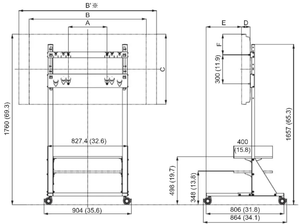
※ スピーカーあり
With speakers
Mit Lautsprechern
Met luidsprekers
Con altoparlanti
Avec les enceintes
Con altavoces
Med högtalare
Med højttalere
С динамиками