
T.Racing Scuderia Ferrari Edition - Headphones THRUSTMASTER - Free user manual and instructions
Find the device manual for free T.Racing Scuderia Ferrari Edition THRUSTMASTER in PDF.

| Product Type | Racing wheel with force feedback |
| Brand | Thrustmaster |
| Model | T-GT Scuderia Ferrari Edition |
| Compatibility | PlayStation 4, PC |
| Rotation angle | 1080 degrees |
| Motor | Dual motorization with force feedback |
| Effects system | T-DFB (compatible PS4 GT mode) |
| Quick Release | Thrustmaster Quick Release (removable axle) |
| Number of buttons | 25 action buttons + 4 rotary selectors + 2 mini-sticks + directional pad |
| Pedal set included | Yes, 3 adjustable metal pedals (accelerator, brake, clutch) |
| Pedal adjustments | Height, spacing, tilt, conical brake MOD |
| Power supply | External T-TURBO power supply, 100-240V AC |
| Connectivity | Detachable USB, pedal connector, TH8A shifter connector |
| Ventilation | Internal fan with automatic cooling |
| Calibration | Automatic (wheel and pedals) |
| Firmware update | Via PC (support.thrustmaster.com) |
| Approximate weight | Approximately 5 kg (wheel + base + pedal set) |
| Maintenance | Clean with a soft dry cloth. Do not use solvents. |
| Safety | Do not play barefoot. Keep out of reach of children. Disconnect if abnormal. |
| Warranty | 2 years (EU), 1 year (other countries) |
Frequently Asked Questions - T.Racing Scuderia Ferrari Edition THRUSTMASTER
User questions about T.Racing Scuderia Ferrari Edition THRUSTMASTER
0 question about this device. Answer the ones you know or ask your own.
Ask a new question about this device
Download the instructions for your Headphones in PDF format for free! Find your manual T.Racing Scuderia Ferrari Edition - THRUSTMASTER and take your electronic device back in hand. On this page are published all the documents necessary for the use of your device. T.Racing Scuderia Ferrari Edition by THRUSTMASTER.
USER MANUAL T.Racing Scuderia Ferrari Edition THRUSTMASTER
natural_image
Technical line drawing of a steering wheel and control panel assembly (no text or symbols)WARNING:
To ensure that your T-GT racing wheel functions correctly with games, you may be required to install the game's automatic updates (available when your system is connected to the Internet).
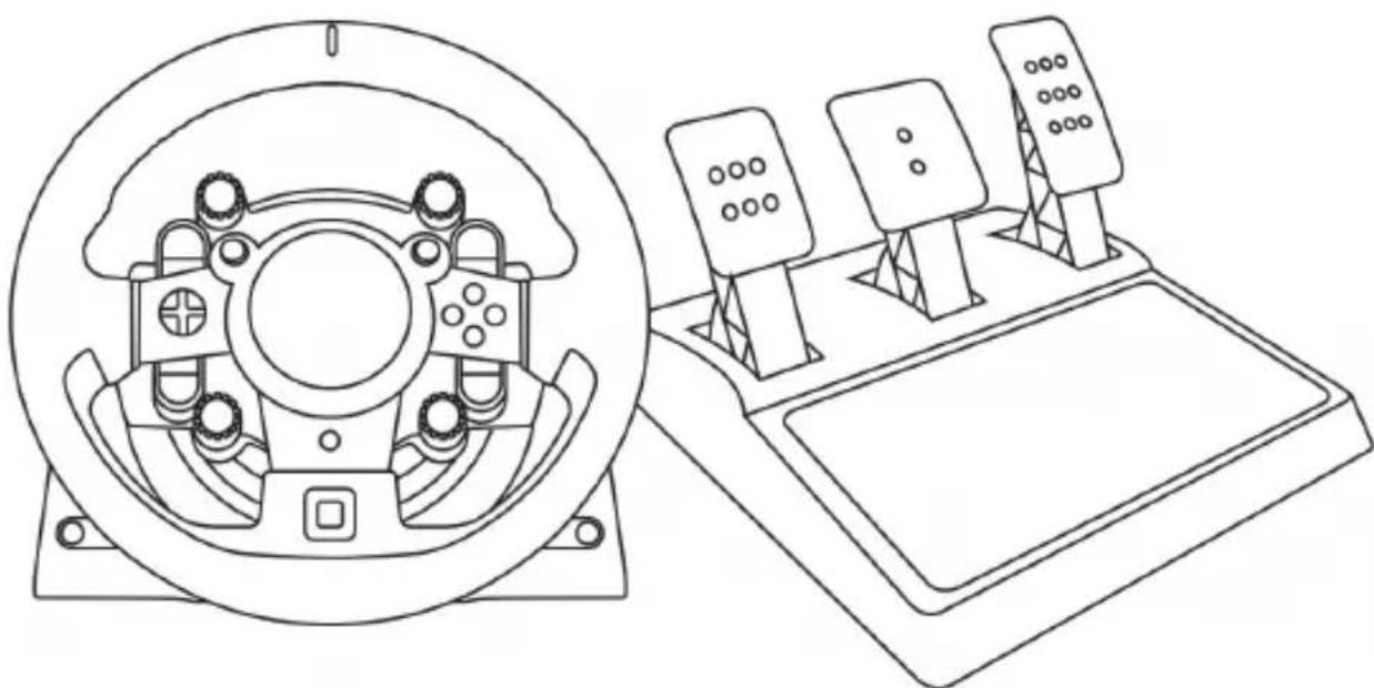
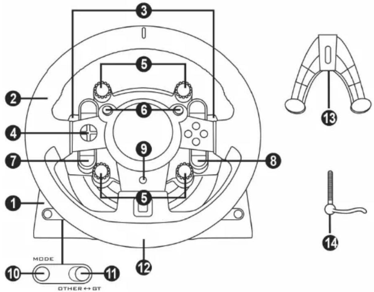
TECHNICAL FEATURES

1 T-GT base
2 T-GT wheel
3 2 sequential paddle shifters (up & down)
4 Directional buttons
5 4 rotary selectors with Push function (compatible with the PS4 ^TM system in GT mode and on PC ^* )
6 2 mini-sticks (compatible with the PS4™ system in GT mode and on PC*)
7 SHARE button
8 OPTIONS button
9 PS button
10 MODE button + red/green indicator light
11 Built-in USB sliding switch: OTHER / GT
12 Large threaded hole (for attachment system and fastening screw)
13 Attachment system
14 Metal fastening screw
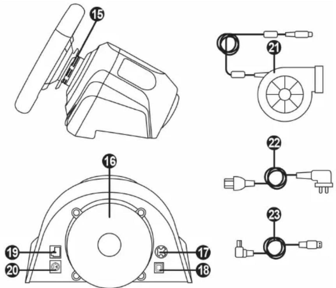
15 Thrustmaster Quick Release
16 T-DFB effects system (only compatible with the PS4 ^TM system in GT mode)
17 Connector for T-TURBO power supply
18 Connector for removable USB cable
19 Connector for pedal set
20 Connector for TH8A shifter (shifter sold separately)
21 T-TURBO power supply
22 Power supply cable
23 Removable USB cable
PLUGGING THE WHEEL INTO AN ELECTRICAL OUTLET: PLEASE READ CAREFULLY!

Never plug the T-TURBO power supply into an electrical outlet with a different voltage! The T-TURBO power supply's voltage is indicated on the label located above the female connector for the power supply cable.

Never connect a power supply other than the T-TURBO power supply to the T-GT base, even if the connector is compatible! For example, never connect the power adapter for the T500 RS wheel to the T-GT base.
WARNING
Before using this product, please read this manual carefully and save it for later reference.

Warning – Electrical shock
* Keep the product in a dry location and do not expose it to dust or sunlight.
* Do not twist or pull on the connectors and cables.
* Do not spill any liquid on the product or its connectors.
* Do not short-circuit the product.
* Never dismantle the product; do not throw it onto a fire and do not expose it to high temperatures.
* Do not use a power supply cable other than the one provided with your racing wheel.
* Do not use the power supply cable if the cable or its connectors are damaged, split or broken.
* Make sure that the power supply cable is properly plugged into an electrical outlet, and properly connected to the connector at the rear of the racing wheel's base.
* Do not open up the racing wheel: there are no user-serviceable parts inside. Any repairs must be carried out by the manufacturer, its authorised representative or a qualified technician.
* Only use attachment systems/accessories specified by the manufacturer.
* If the racing wheel is operating abnormally (if it is emitting any abnormal sounds, heat or odours), stop using it immediately, unplug the power supply cable from the electrical outlet and disconnect the other cables.
* If you will not be using the racing wheel for an extended period of time, unplug its power supply cable from the electrical outlet.
* The electrical outlet must be located near the equipment and must be easily accessible.

Air vents
Make sure not to block any of the air vents on the racing wheel's base. For optimal ventilation, make sure to do the following:
* Position the wheel's base at least 10c m away from any wall surfaces.
* Do not place the base in any tight spaces.
* Do not cover the base.
* Do not let any dust build up on the air vents.

For safety reasons, never use the pedal set with bare feet or while wearing only socks on your feet.
THRUSTMASTER® DISCLAIMS ALL RESPONSIBILITY IN THE EVENT OF INJURY RESULTING FROM USE OF THE PEDAL SET WITHOUT SHOES.

Warning – Injuries due to Force Feedback and repeated movements
Playing with a Force Feedback racing wheel may cause muscle or joint pain. To avoid any problems:
* Avoid lengthy gaming periods.
* Take 10 to 15 minute breaks after each hour of play.
* If you feel any fatigue or pain in your hands, wrists, arms, feet or legs, stop playing and rest for a few hours before you start playing again.

Warning – Injuries due to Force Feedback and repeated movements (continued)
* If the symptoms or pain indicated persist when you start playing again, stop playing and consult your doctor.
* Keep out of children's reach.
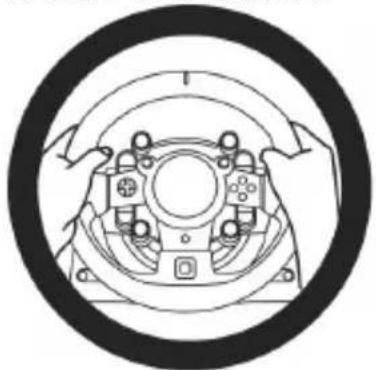
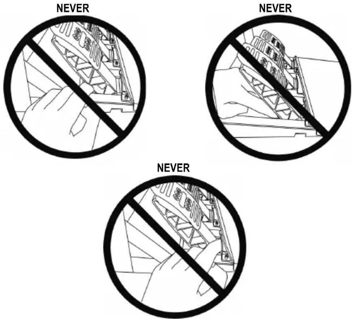
* During gameplay, always leave both hands correctly positioned on the wheel without completely letting go.
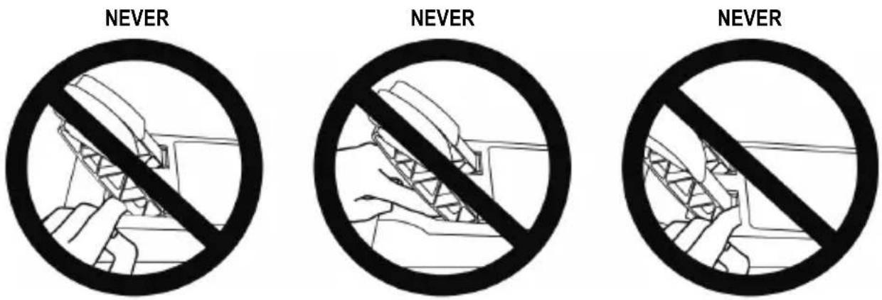
* During gameplay, never place your hands or your fingers under the pedals or anywhere near the pedal set.
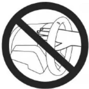
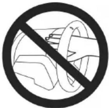
* During calibration and gameplay, never place your hand or your arm through the openings in the racing wheel.
* Make sure that the racing wheel's base is properly secured, as per this manual's instructions.

Product to be handled only by users 16 years of age or older
HEAVY PRODUCT
Be careful not to drop the product on yourself or on anyone else!
ALWAYS NEVER NEVER
natural_image
Diagram of a mechanical assembly with rotating components and directional arrows (no text or symbols)


Warning – Pedal set pinch hazard when playing
* Keep the pedal set out of children's reach.
* During gameplay, never place your fingers on or anywhere near the sides of the pedals.
* During gameplay, never place your fingers on or anywhere near the pedal's rear base.
* During gameplay, never place your fingers on or anywhere near the pedal's front base.

Warning – Pedal set pinch hazard when not playing
* Store the pedal set in a safe place, and keep it out of children's reach.
UPDATING YOUR RACING WHEEL'S FIRMWARE
The firmware included in your racing wheel's base can be updated to a more recent version featuring product enhancements.
To display the firmware version that your racing wheel is currently using and update it if required: on PC, visit http://support.thrustmaster.com. Click Racing Wheels / T-GT, then select Firmware and follow the instructions describing the download and installation procedure.
Important note:
On PC, the USB sliding switch (11) on the racing wheel's base must always be set to the "OTHER" position.
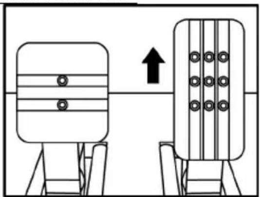
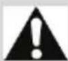
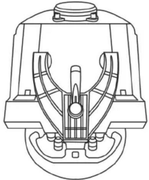
INSTALLING THE WHEEL ON ITS BASE
Align the connector positions using the arrows:
Base (1) connector: Arrow pointing upwards
Racing wheel (2) connector: Arrow pointing upwards
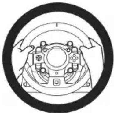
Once the connectors are correctly positioned, simply rotate the Thrustmaster Quick Release (15) device's ring anticlockwise, while holding the racing wheel (2) in position.
Then, tighten the ring as much as you can: to do so, hold the ring in position and rotate the racing wheel clockwise.

flowchart
graph TD
    A["Wheel rim"] --> B["Target"]
    B --> C["Motor Component"]
    C --> D["Assembly"]
    D --> E["Motor Component"]
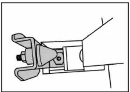
Once you have installed the wheel, rotate it 180^ (when facing the wheel, the GT logo should be upside down) to access the small attachment screw located on the ring of the Thrustmaster Quick Release (15) device. Use a large Phillips screwdriver to tighten the small attachment screw (do not use excessive force), turning it clockwise.

When using a Philips screwdriver, ensure NOT to use excessive force when tightening the small attachment screw!
Stop turning the screw as soon as you feel some resistance.
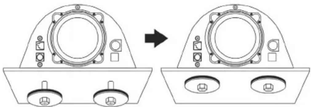
ATTACHING THE RACING WHEEL
Attaching the racing wheel's base to a cockpit
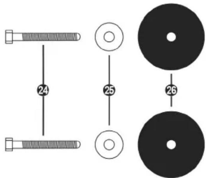
24 2 M6-type hexagon head/Phillips-head bolts
25 2 washers
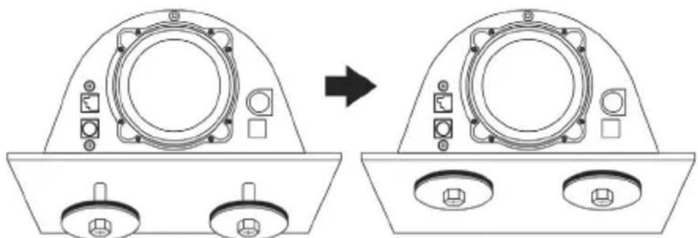
26 2 mounting discs (metal on one side, and textured rubber on the other)

natural_image
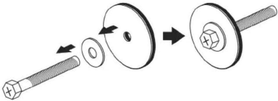
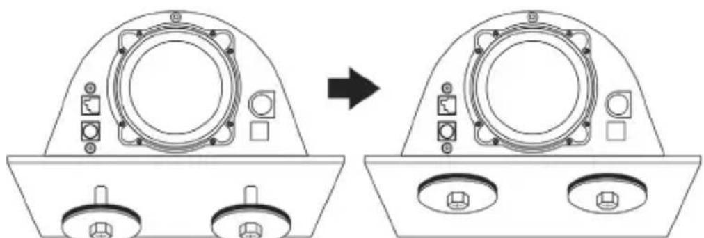
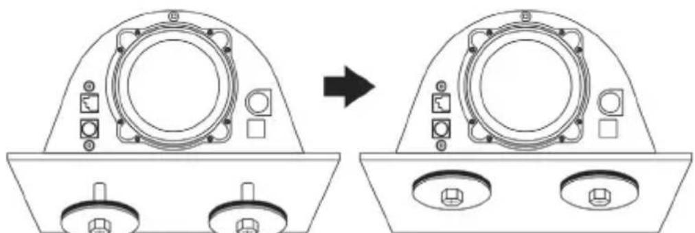
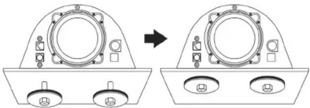
Technical line drawing showing a device component before and after assembly, with no visible text or symbols.- Position the washers (25) on the metal sides of the mounting discs (26), and insert the M6-type hexagon head/Phillips-head bolts (24).
- Place the racing wheel's base on the cockpit shelf.
- Using a 10 mm wrench key or a Phillips-head screwdriver, screw the cockpit mounting kit into the cockpit shelf and into the 2 small screw threads located on the underside of the wheel.
ATTENTION:
- Do not remove the foam pads located on the underside of the racing wheel's base! The foam pads amplify the effects of the T-DFB system when the wheel is attached.
- The textured rubber side of the mounting discs (26) must imperatively be positioned facing the cockpit shelf = never position the metal side facing the cockpit shelf.
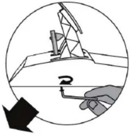
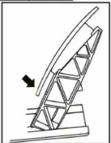
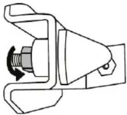
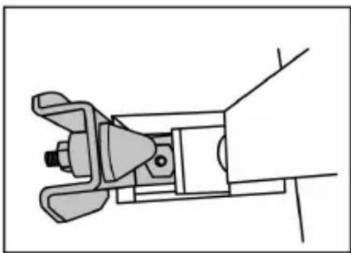
Attaching the racing wheel to a table or a desktop
- Place the racing wheel on a table or any other horizontal, flat and stable surface.
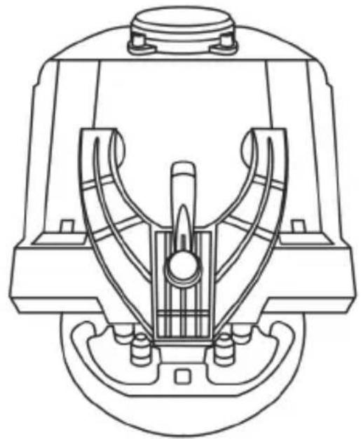
- Insert the fastening screw (14) in the attachment system (13), then tighten the device by turning the screw anticlockwise, so that it feeds into the large threaded hole (12) located beneath the racing wheel, until the wheel is perfectly stable.
ALWAYS NEVER
natural_image
Technical line drawing of a mechanical assembly with no visible text or symbols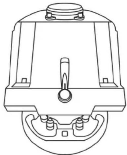
natural_image
Technical line drawing of a mechanical component with no visible text or symbolsWARNING:
- Never tighten the screw alone, without the attachment system in place (this could damage the racing wheel).
- Do not remove the foam pads located on the underside of the racing wheel's base! The foam pads amplify the effects of the T-DFB system when the wheel is attached.
| ATTACHMENT / REMOVAL | DIRECTION |
| To tighten:Turn the screw anticlockwise | 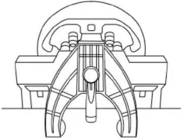 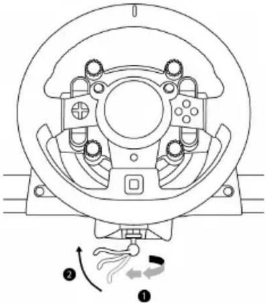 |
| To release:Turn the screw clockwise | 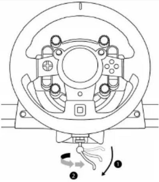 |
SETTING UP THE RACING WHEEL FOR PS4™
- Connect the pedal set to its connector (19) located at the rear of the racing wheel's base.
- Connect the T-TURBO power supply (21) to its connector (17).
- Connect the power supply cable (22) to the T-TURBO power supply, and plug the cable into an electrical outlet with the same voltage.
- Set the USB sliding switch (11) to the "OTHER" or "GT" position, depending on the PS4™ game you are using.
- Connect the removable USB cable (23) to its connector (18) and to one of the USB ports on the PS4 ^™ system.
- Once your PS4 ^TM system is powered on, your racing wheel will calibrate itself.
- Press the PS button (9) on the racing wheel, and log in to your Sony Entertainment Network account in order for your wheel to be functional.
You are now ready to play!
Important notes:
- Don't forget to press the PS button (9) on the racing wheel, in order for your wheel to be functional.
- The USB sliding switch (11) on the wheel's base must always be set to the proper position ("OTHER" or "GT") before connecting the racing wheel's USB cable to your system. To change the sliding switch's position: disconnect the USB cable, and then set the switch to the appropriate position before reconnecting the USB cable to the system.
- The list of PlayStation®4 games compatible with the T-GT (along with the required position for the USB sliding switch (11) according to the game you are using) is available here: http://support.thrustmaster.com (in the Racing Wheels/T-GT section). This list is updated regularly.
USB SLIDING SWITCH (11) IN THE "OTHER" POSITION
FOR PS4™ GAMES APART FROM GT SPORT
When the USB sliding switch (11) is set to the "OTHER" position:
* The wheel is recognized in most games as a T300 RS wheel.
* The 4 rotary selectors with Push function (5) are not functional.
* The 2 mini-sticks (6) are not functional.
* The Force Feedback system is functional, but the T-DFB effects system (16) is not.
USB SLIDING SWITCH (11) IN THE "GT" POSITION FOR THE GAME GT SPORT (AND OTHER FUTURE GT GAMES)
When the USB sliding switch (11) is set to the "GT" position:
* The wheel is recognized as a T-GT wheel.
* The 4 rotary selectors with Push function (5) are functional.
* The 2 mini-sticks (6) are functional.
* The Force Feedback system, and the T-DFB effects system (16), are both functional at the same time. In the GT Sport game's options, the power level of each system can be adjusted independently.
SETTING UP THE RACING WHEEL FOR PC\*
*PC compatibility neither tested nor endorsed by Sony Interactive Entertainment Europe.
For more information, visit http://support.thrustmaster.com.
AUTOMATIC RACING WHEEL AND PEDAL SET CALIBRATION
The wheel automatically self-calibrates when you plug the racing wheel into an electrical outlet and connect the racing wheel's USB connector to the system.
During this phase, the racing wheel will rotate quickly towards the left and the right, covering a 1080 degree angle, before stopping at the center.

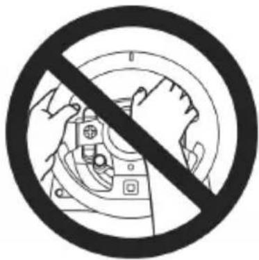
Never touch the racing wheel during the self-calibration phase! (This could result in improper calibration and/or personal injuries.)
AUTOMATIC CALIBRATION OF THE PEDAL SET
Never connect the pedal set to the racing wheel's base (or disconnect it from the base) when it is connected to the system or during gameplay (this could result in improper calibration).
Always connect the pedal set before connecting the racing wheel to the system.
Once the racing wheel's calibration is complete and the game has been started, the pedals are automatically calibrated after a few presses.

Never press the pedals during the racing wheel's self-calibration phase or while a game is loading! (This could result in improper calibration.)
If your racing wheel and/or pedal set do not function correctly, or if they seem to be improperly calibrated:
Power off your system and completely disconnect the racing wheel. Then reconnect all cables (including the power supply cable and the pedal set), and restart your system and your game.
INTERNAL COOLING SYSTEM FOR THE WHEEL'S BASE
The internal cooling system for the wheel's base
- starts working when the wheel is powered on.
- switches off after a few minutes of inactivity when the internal temperature cools down to a low level.
- switches on again when you use the wheel.
MODE BUTTON AND INDICATOR LIGHT (10)
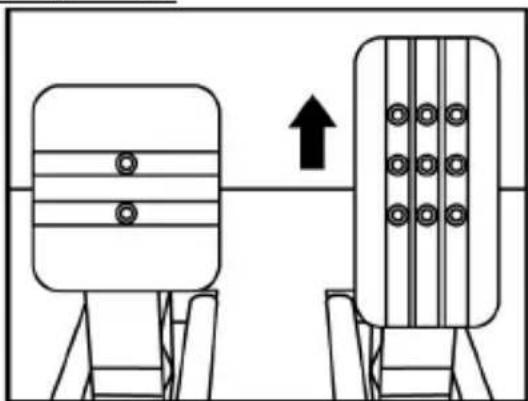
MODE button for the pedal set
You can electronically swap the accelerator and clutch pedals.
To do so, simply press the MODE button (10) for 2 seconds.
The racing wheel's internal memory stores whether the pedals have been swapped around or not.
| GAS AND CLUTCH PEDALS | Colour of the MODE indicator light (10) |
| NORMAL | RED |
| SWAPPED AROUND | GREEN |
Other information regarding the MODE button
To learn more about the MODE button and indicator light, please visit http://support.thrustmaster.com. Click Racing Wheels / T-GT, and then select Manual or FAQ.
HELP FILES AND FAQs
Please visit http://support.thrustmaster.com. Click Racing Wheels / T-GT, and then select Manual or FAQ.
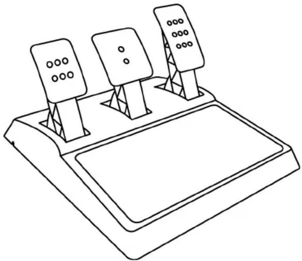
T-GT EDITION PEDAL SET

natural_image
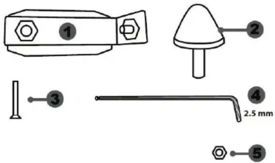
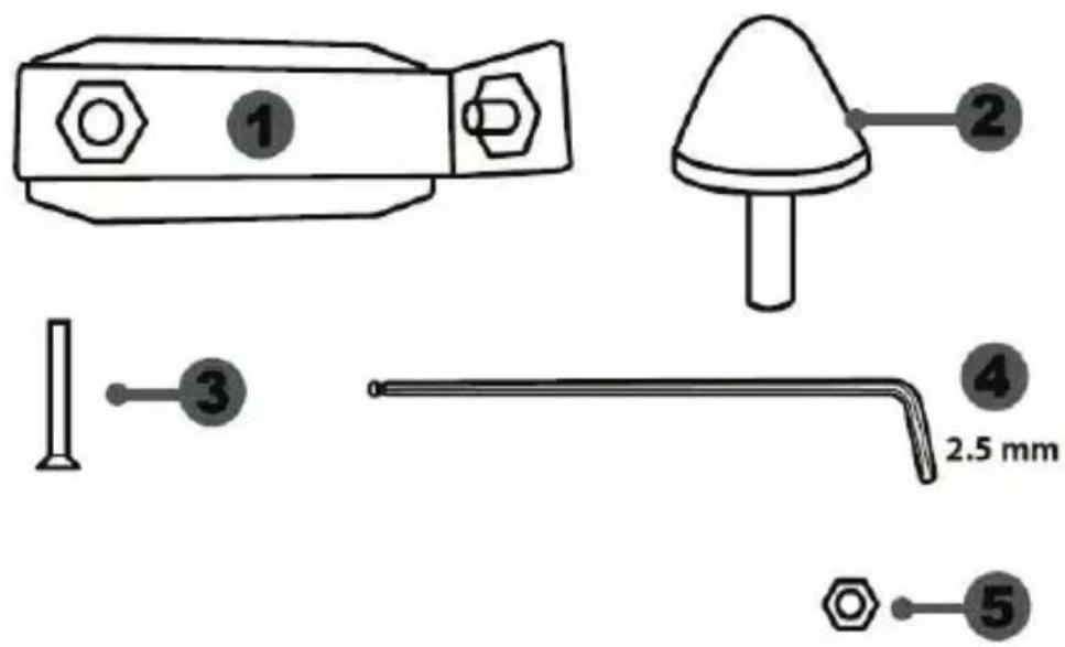
Line drawing of a device with three speakers on top (no text or symbols)TECHNICAL FEATURES

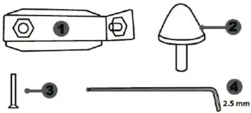
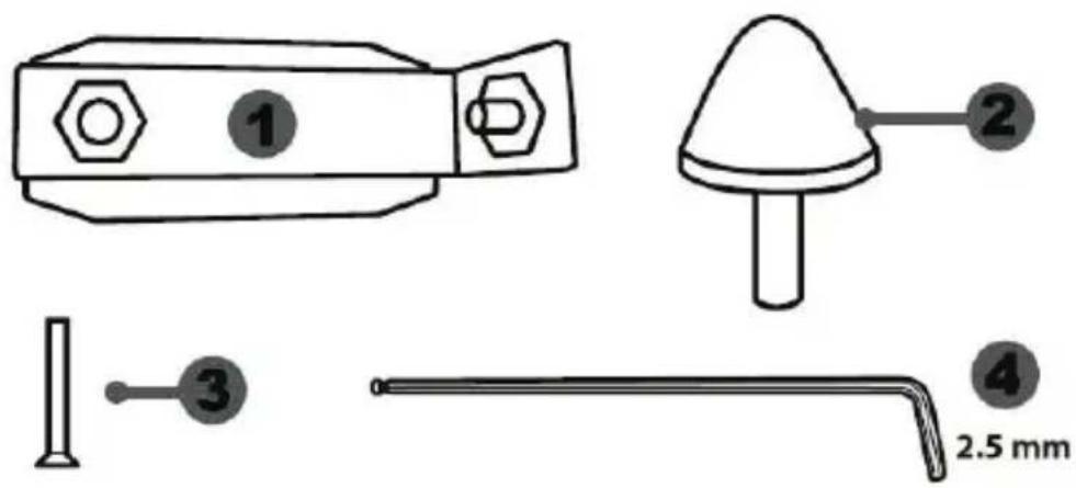
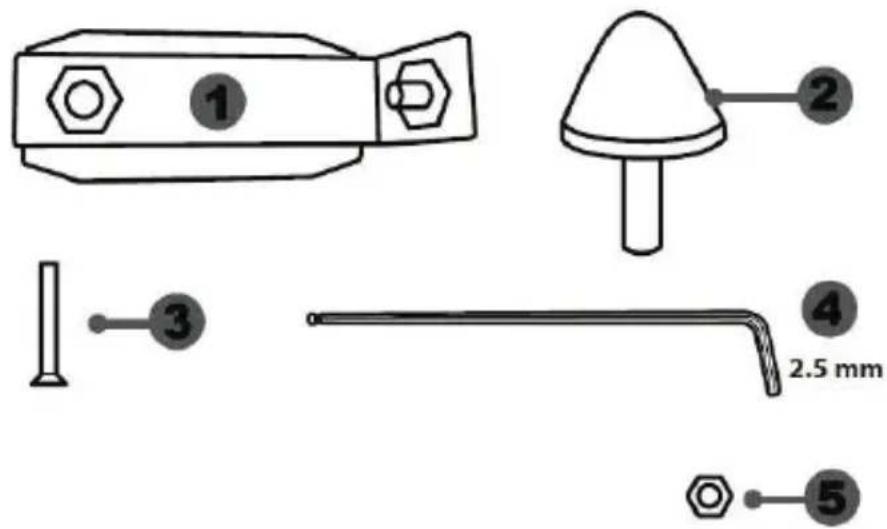
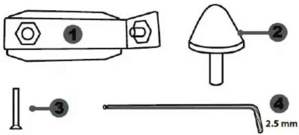
1 Metal support for conical stop (not installed by default)
2 Conical stop
3 Attachment screw for metal support
4 2.5 mm Allen key (included)
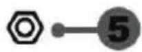
5 Position adjustment nut for conical stop
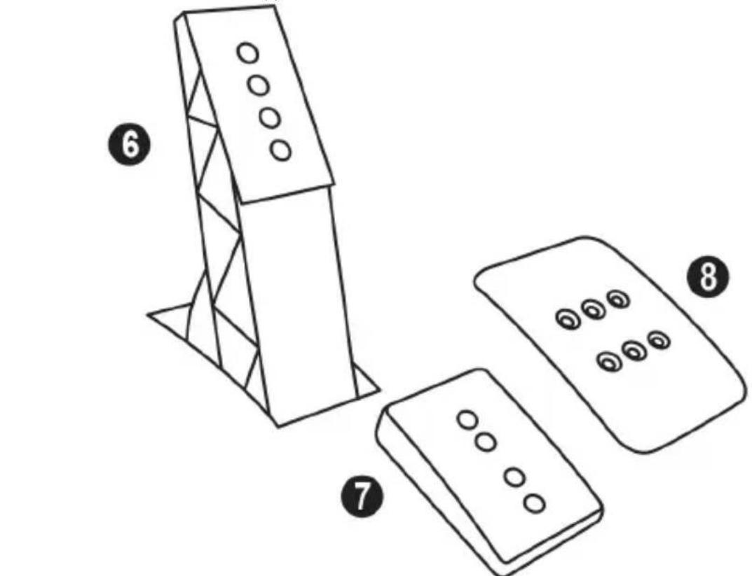
6 Metal pedal arm
7 Plastic head support
8 Metal pedal head
WARNING
Before using this product, be sure to read these instructions carefully and save them for future reference.

For safety reasons, never use the pedal set with bare feet or while wearing only socks on your feet.
THRUSTMASTER® DISCLAIMS ALL RESPONSIBILITY IN THE EVENT OF INJURY RESULTING FROM USE OF THE PEDAL SET WITHOUT SHOES.

Warning – Pedal set pinching hazard during gaming sessions
* Keep the pedal set out of the reach of children.
* During gaming sessions, never place your fingers or thumbs on or near the sides of the pedals.
* During gaming sessions, never place your fingers or thumbs on or near the rear base of the pedals.
* During gaming sessions, never place your fingers or thumbs on or near the front base of the pedals.
AUTOMATIC CALIBRATION OF PEDALS

- Never connect or disconnect the pedal set from the base of the wheel when the wheel is connected to a PS4™ system or to a PC, or during gaming sessions, to avoid calibration problems.
= Always connect the pedal set to the wheel before connecting the wheel to a PS4™ system or to a PC. - Once the wheel has self-calibrated and the game has started, the pedals automatically calibrate themselves after being pressed a few times.
- Never press on the pedals when the wheel is self-calibrating or when your game is starting up, to avoid calibration problems.
- If the pedals are not functioning correctly or appear to be improperly calibrated, power off your system, completely disconnect your wheel, then reconnect all of the cables (including the power supply cable and the pedal set cable), power the system back on and restart your game.
ATTACHING THE PEDAL SET TO A COCKPIT
- Attach the pedal set using the small screw threads located on the underside of the pedal set.
- Screw two M6 screws (not included) into the cockpit's pedal support plate and into the two small screw threads located on the underside of the pedal set.
Important: The length of the two M6 screws must not exceed the thickness of the cockpit's pedal support plate plus an additional 10 mm, to avoid damaging the pedal set's internal components.
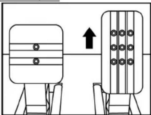
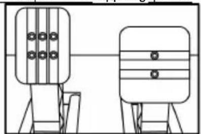
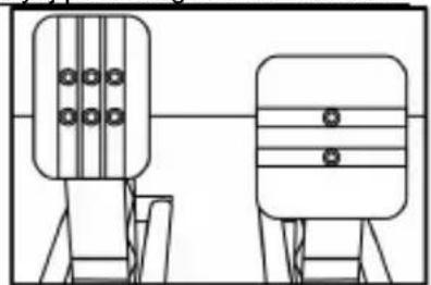
ADJUSTING THE PEDAL SET
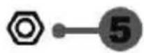
Each of the three pedals includes:
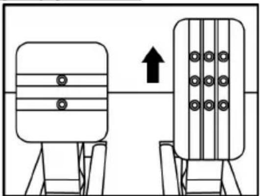
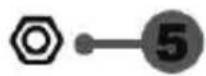
- A metal head (8) with multiple perforations (nine for the accelerator – two for the brake – six for the clutch).
- A plastic head support (7) (placed between the head and the arm) with four perforations.
- A metal pedal arm (6) with four perforations.

ATTENTION: To avoid any calibration problems, be sure to always disconnect your wheel's USB cable from the PS4™ system before making any adjustments to your pedal set.
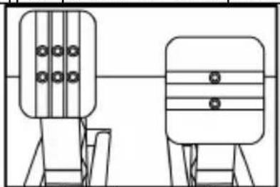
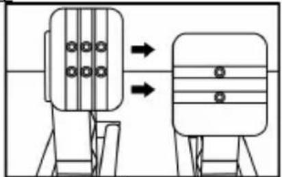
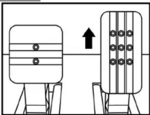
Adjusting the HEIGHT of the 3 pedals
- Using the included 2.5 mm Allen key (4), unscrew the two screws holding the metal head (8) and its support (7) in place.
- Select your preferred height position, then replace and re-tighten the screws so that the metal head (8) and its support (7) are held firmly in place.
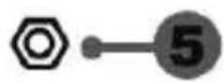
Examples illustrating the accelerator pedal:

natural_image
Diagram showing two mechanical components with a downward arrow indicating motion or change (no text or symbols)Low position
natural_image
Diagram showing two identical mechanical components with a directional arrow, no text or symbols presentHigh position
Adjusting the SPACING of the accelerator pedal and the clutch pedal
- Using the included 2.5 mm Allen key (4), unscrew the two screws holding the metal head (8) and its support (7) in place.
- Select your preferred position (to the left, centered, or to the right), then replace and re-tighten the screws so that the metal head (8) and its support (7) are held firmly in place.
Examples illustrating the clutch pedal:

natural_image
Diagram showing two mechanical components with arrows indicating direction, no text or symbols presentLeft position

natural_image
Two identical mechanical devices with circular components mounted on stands, no visible text or symbolsCentered position (default)

natural_image
Diagram showing two mechanical components with arrows indicating motion or assembly (no text or symbols)Right position
Number of possible spacing positions per pedal:
- Three for accelerator pedal
- Three for clutch pedal
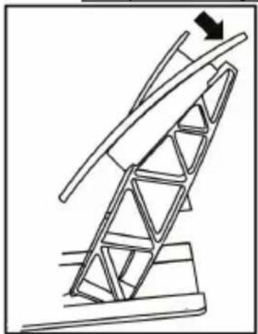
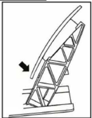
Adjusting the INCLINATION of the 3 pedals
- Using the included 2.5 mm Allen key (4), unscrew the two screws holding the metal head (8) and its support (7) in place.
- Turn the plastic head support (7) 180°, then replace and re-tighten the screws so that the metal head (8) and its support (7) are held firmly in place.
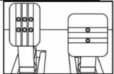
Examples illustrating the accelerator pedal:
natural_image
Technical line drawing of a mechanical structure with an arrow indicating upward motion (no text or symbols)Less inclined position
natural_image
Diagram of a mechanical structure with an arrow indicating direction, no text or symbols presentMore inclined position (default)
Number of possible inclination positions per pedal:
- Two for accelerator pedal
- Two for brake pedal
- Two for clutch pedal
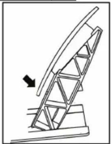
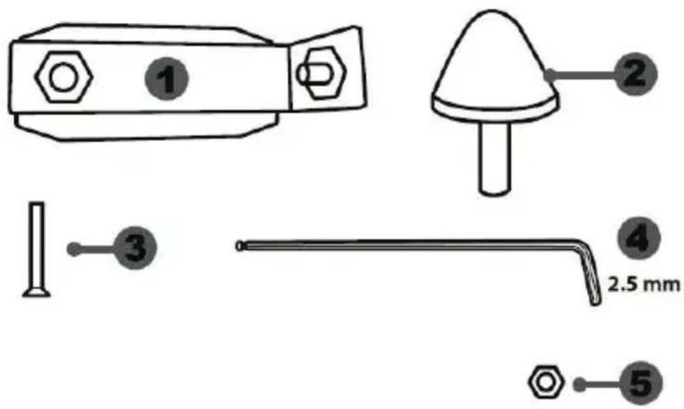
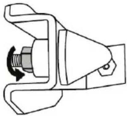
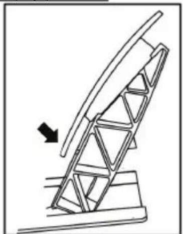
Installing the conical stop ("CONICAL RUBBER BRAKE" mod)
This modification (or "mod") is not essential, and is not installed by default. This means that the brake pedal functions perfectly even if the mod is not installed.
This mod lets you experience a different feeling and resistance when braking.
It's up to you whether or not to install it, depending on your own preferences.
- Screw the conical stop (2) onto its metal support (1).
- Screw the position adjustment nut (5) onto the bottom (onto the conical stop's screw thread).

- Position the unit at the back of the brake pedal's arm.

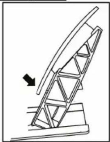
- Using the included 2.5 mm Allen key (4), attach the unit using the attachment screw (3) and the small central screw thread located on the underside of the pedal set.
natural_image
Diagram showing a hand holding a tool inside a circular frame with an arrow and a magnifying glass, no text or symbols present.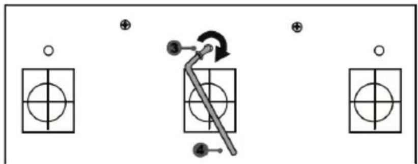
flowchart
graph TD
    A["○"] --> B["○"]
    C["⊕"] --> D["○"]
    E["●"] --> F["○"]
    G["⊕"] --> H["○"]
    I["●"] --> J["○"]
    K["●"] --> L["○"]
    M["●"] --> N["○"]
    O["●"] --> P["○"]
The "CONICAL RUBBER BRAKE" mod is now installed!
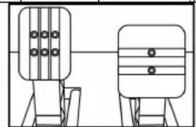
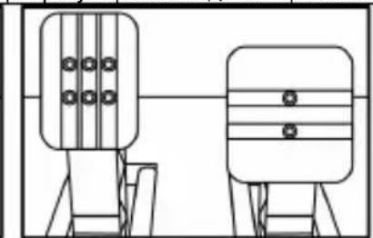
Adjusting the brake pedal's RANGE of travel and STRENGTH of resistance
By slightly unscrewing the nut (5), you can further strengthen the resistance of the brake pedal by moving the conical stop (2) closer to the back of the pedal's arm (if necessary, use a 14 mm wrench or pliers to re-tighten the nut and maintain the selected position). The closer the conical stop is positioned to the back of the pedal's arm, the greater the strength of resistance will be.

natural_image
Mechanical component diagram showing a valve mechanism with directional arrows (no text or symbols)Note: When the conical stop is very close to the back of the brake pedal's arm, you may experience difficulties in reaching the maximum calibration value. Should that be the case:
* Slowly, press very hard on the brake pedal so as to reach the maximum value (if necessary, stand very briefly on the pedal – just for a second), then release the pressure; or else
* Move the conical stop a bit farther away from the back of the brake pedal's arm.
CONSUMER WARRANTY INFORMATION
Worldwide, Guillemot Corporation S.A., whose registered office is located at Place du Granier, B.P. 97143, 35571 Chantepie, France (hereinafter “Guillemot”) warrants to the consumer that this Thrustmaster product shall be free from defects in materials and workmanship, for a warranty period which corresponds to the time limit to bring an action for conformity with respect to this product. In the countries of the European Union, this corresponds to a period of two (2) years from delivery of the Thrustmaster product. In other countries, the warranty period corresponds to the time limit to bring an action for conformity with respect to the Thrustmaster product according to applicable laws of the country in which the consumer was domiciled on the date of purchase of the Thrustmaster product (if no such action exists in the corresponding country, then the warranty period shall be one (1) year from the original date of purchase of the Thrustmaster product).
Notwithstanding the above, rechargeable batteries are covered by a warranty period of six (6) months from the date of original purchase.
Should the product appear to be defective during the warranty period, immediately contact Technical Support, who will indicate the procedure to follow. If the defect is confirmed, the product must be returned to its place of purchase (or any other location indicated by Technical Support).
Within the context of this warranty, the consumer's defective product shall, at Technical Support's option, be either replaced or returned to working order. If, during the warranty period, the Thrustmaster product is subject to such reconditioning, any period of at least seven (7) days during which the product is out of use shall be added to the remaining warranty period (this period runs from the date of the consumer's request for intervention or from the date on which the product in question is made available for reconditioning, if the date on which the product is made available for reconditioning is subsequent to the date of the request for intervention). If permitted under applicable law, the full liability of Guillemot and its subsidiaries (including for consequential damages) is limited to the return to working order or the replacement of the Thrustmaster product. If permitted under applicable law, Guillemot disclaims all warranties of merchantability or fitness for a particular purpose.
This warranty shall not apply: (1) if the product has been modified, opened, altered, or has suffered damage as a result of inappropriate or abusive use, negligence, an accident, normal wear, or any other cause unrelated to a material or manufacturing defect (including, but not limited to, combining the Thrustmaster product with any unsuitable element, including in particular power supplies, rechargeable batteries, chargers, or any other elements not supplied by Guillemot for this product); (2) if the product has been used for any use other than home use, including for professional or commercial purposes (game rooms, training, competitions, for example); (3) in the event of failure to comply with the instructions provided by Technical Support; (4) to software, said software being subject to a specific warranty; (5) to consumables (elements to be replaced over the product's lifespan: disposable batteries, audio headset or headphone ear pads, for example); (6) to accessories (cables, cases, pouches, bags, wrist-straps, for example); (7) if the product was sold at public auction.
This warranty is nontransferable.
The consumer's legal rights with respect to laws applicable to the sale of consumer goods in his or her country are not affected by this warranty.
Additional warranty provisions
During the warranty period, Guillemot shall not provide, in principle, any spare parts, as Technical Support is the only party authorized to open and/or recondition any Thrustmaster product (with the exception of any reconditioning procedures which Technical Support may request that the consumer carry out, by way of written instructions – for example, due to the simplicity and the lack of confidentiality of the reconditioning process – and by providing the consumer with the required spare part(s), where applicable).
Given its innovation cycles and in order to protect its know-how and trade secrets, Guillemot shall not provide, in principle, any reconditioning notification or spare parts for any Thrustmaster product whose warranty period has expired.
Liability
If permitted under applicable law, Guillemot Corporation S.A. (hereinafter "Guillemot") and its subsidiaries disclaim all liability for any damages caused by one or more of the following: (1) the product has been modified, opened or altered; (2) failure to comply with assembly instructions; (3) inappropriate or abusive use, negligence, an accident (an impact, for example); (4) normal wear; (5) the use of the product for any use other than home use, including for professional or commercial purposes (game rooms, training, competitions, for example). If permitted under applicable law, Guillemot and its subsidiaries disclaim all liability for any damages unrelated to a material or manufacturing defect with respect to the product (including, but not limited to, any damages caused directly or indirectly by any software, or by combining the Thrustmaster product with any unsuitable element, including in particular power supplies, rechargeable batteries, chargers, or any other elements not supplied by Guillemot for this product).

COPYRIGHT
© 2017 Guillemot Corporation S.A. All rights reserved. Thrustmaster® is a registered trademark of Guillemot Corporation S.A.
Licensed for sale in Europe, Africa, Middle East, Russia, India and Oceania. For use exclusively with PlayStation®4.
All other trademarks and brand names are hereby acknowledged and are property of their respective owners. Illustrations not binding. Contents, designs and specifications are subject to change without notice and may vary from one country to another. Made in China.
Manufactured and distributed by Guillemot Corporation S.A.
TouchSense® technology licensed from Immersion Software Ireland Limited. Protected by one or more of the U.S. Patents found at the following address: www.immersion.com/patent-marking.html, and other patents pending.
ENVIRONMENTAL PROTECTION RECOMMENDATION
natural_image
Simple line drawing of a trash bin with no text or symbolsIn the European Union and Turkey: At the end of its working life, this product should not be disposed of with standard household waste, but rather dropped off at a collection point for the disposal of Waste Electrical and Electronic Equipment (WEEE) for recycling.
This is confirmed by the symbol found on the product, user manual or packaging. Depending on their characteristics, the materials may be recycled. Through recycling and other forms of processing Waste Electrical and Electronic Equipment,
you can make a significant contribution towards helping to protect the environment.
Please contact your local authorities for information on the collection point nearest you.
For all other countries: Please adhere to local recycling laws for electrical and electronic equipment.
Retain this information. Colours and decorations may vary.
Plastic fasteners and adhesives should be removed from the product before it is used.
www.thrustmaster.com
*Applicable to EU and Turkey only

immersion.

T-GT
natural_image
Technical line drawing of a steering wheel and motor control panel (no text or symbols)ATTENTION :
natural_image
Diagram of a mechanical assembly with hands holding a central component, enclosed in a circular frame (no text or symbols)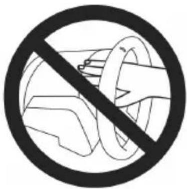


flowchart
graph TD
    A["Wheel Hub"] --> B["Assembly Gear Component"]
    B --> C["Motor Assembly"]
    C --> D["Final Gear Component with Arrow indicating motion"]

natural_image
Diagram showing a device component before and after transformation, with no visible text or symbols.natural_image
Technical line drawing of a mechanical component with no visible text or symbols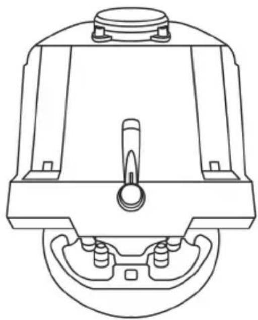
natural_image
Technical line drawing of a mechanical component with no visible text or symbolsATTENTION :
natural_image
Line drawing of a device with three speakers on top (no text or symbols)CARACTÉRISTIQUES TECHNIQUES
natural_image
Diagram showing two mechanical components with a downward arrow indicating motion or change (no text or symbols present)Position basse

natural_image
Diagram showing two identical mechanical components with a central arrow indicating upward motion (no text or symbols)Position haute
natural_image
Diagram of a mechanical device with two views showing internal components and directional arrows (no text or symbols)Position à gauche

natural_image
Technical line drawing of two mechanical components with no visible text or symbolsnatural_image
Diagram showing two mechanical components with arrows indicating direction of movement (no text or symbols)Position à droite
natural_image
Diagram of a mechanical structure with a triangular frame and an arrow indicating upward motion (no text or symbols)natural_image
Diagram of a ladder structure with an arrow indicating direction (no text or symbols present)natural_image
Illustration of an oil pumpjack inside a circle with a hand holding a tool, no text or symbols present.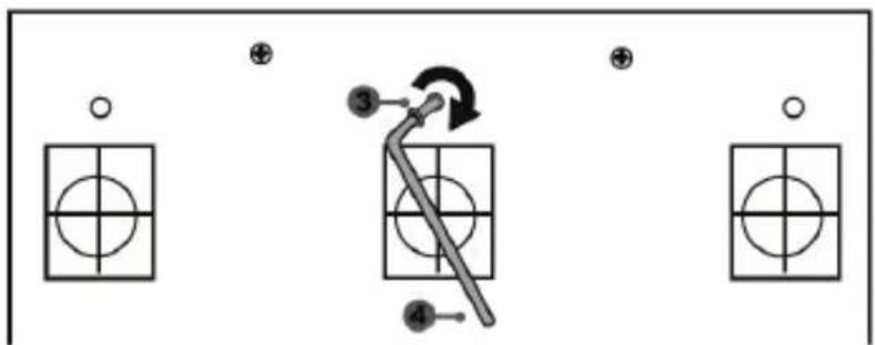
natural_image
Mechanical assembly diagram showing a valve mechanism with two directional arrows indicating flow or movement (no text or labels)INFORMATIONS RELATIVES A LA GARANTIE AUX CONSOMMATEURS
natural_image
Symbol of a trash bin crossed with a diagonal line and a black rectangle below (no text or labels)T-GT
Benutzerhandbuch

natural_image
Technical line drawing of a car steering wheel and its control panel (no text or symbols)ACHTUNG!
natural_image
Diagram of a mechanical device with rotating arms and housing (no text or symbols)


natural_image
Technical line drawing showing a device component before and after assembly, with no visible text or symbols.natural_image
Technical line drawing of a mechanical device with internal components and mounting feet (no text or symbols)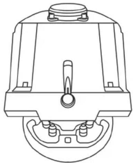
natural_image
Technical line drawing of a mechanical component with no visible text or symbolsACHTUNG:
T-GT EDITION-PEDALSET

natural_image
Line drawing of a device with three speakers on top (no text or symbols)TECHNISCHE MERKMALE
EINBAU DES PEDALSETS IN EIN COCKPIT
ANPASSEN DES PEDALSETS
natural_image
Diagram showing two identical mechanical components with a downward arrow indicating transformation or alignment (no text or symbols present)Niedrige Position

natural_image
Diagram showing two identical mechanical components with a directional arrow, no text or symbols presentHohe Position
natural_image
Diagram showing two mechanical components with arrows indicating direction, no text or symbols presentLinke Position
natural_image
Two identical mechanical components with vertical bars and circular holes, mounted on support poles (no text or symbols)natural_image
Diagram showing two mechanical components with arrows indicating motion or assembly (no text or symbols)Rechte Position
natural_image
Diagram of a ladder structure with an arrow indicating upward motion (no text or symbols present)natural_image
Diagram of a mechanical ladder system with an arrow indicating motion direction (no text or symbols)natural_image
Illustration of an oil pumpjack inside a circular frame, with a hand holding a tool and a downward arrow indicating rotation (no text or symbols)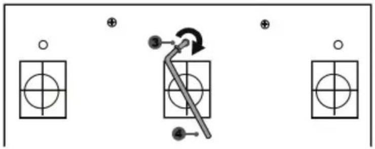
flowchart
graph TD
    A["○"] --> B["○"]
    C["⊕"] --> D["○"]
    E["●"] --> F["○"]
    G["⊕"] --> H["○"]
    I["●"] --> J["○"]
    K["●"] --> L["○"]
    M["●"] --> N["○"]
    O["●"] --> P["○"]
    Q["●"] --> R["○"]
    S["●"] --> T["○"]
    U["●"] --> V["○"]
    W["●"] --> X["○"]
    Y["●"] --> Z["○"]
natural_image
Mechanical component diagram showing a valve mechanism with directional arrows (no text or labels)natural_image
Symbol of a trash bin with crossed lines and a black rectangular base (no text or labels)www.thrustmaster.com
T-GT
Handleiding

natural_image
Technical line drawing of a steering wheel and motor control panel (no text or symbols)WAARSCHUWING:
natural_image
Diagram of hands operating a mechanical device within a circular frame (no text or symbols)


flowchart
graph TD
    A["Wheel Hub"] --> B["Assembly Gear Component"]
    B --> C["Motor Assembly"]
    C --> D["Final Gear Component with Arrow indicating motion"]
natural_image
Technical line drawing showing a device component before and after assembly, with no visible text or symbols.natural_image
Technical line drawing of a mechanical device with internal components and mounting feet (no text or symbols)
natural_image
Technical line drawing of a mechanical component with no visible text or symbolsWAARSCHUWING:
USB-SCHUIFSCHAKELAAR (11) IN DE STAND "OTHER"
VOOR PS4™-GAMES MET UITZONDERING VAN GT SPORT
T-GT EDITION-PEDAALSET
natural_image
Line drawing of a device with three speakers on top (no text or symbols)6 Metalel pedaalarm
7 Kunststof pedaalsteun
8 Metalen pedaal
WAARSCHUWING
DE PEDAALSET AAN EEN COCKPIT BEVESTIGEN
natural_image
Diagram showing two mechanical components with a downward arrow indicating motion or change (no text or symbols)Lage stand

natural_image
Diagram showing two identical mechanical components with a central arrow indicating direction (no text or symbols)Hoge stand
natural_image
Diagram showing two mechanical components with arrows indicating direction, no text or symbols presentLinks

natural_image
Two identical mechanical or architectural diagrams with vertical bars and circular elements, no text or symbols present.natural_image
Diagram showing two mechanical components with arrows indicating motion or assembly (no text or symbols)Rechts
natural_image
Diagram of a mechanical structure with triangular supports and a directional arrow (no text or symbols)Kleine hoek
natural_image
Diagram of a mechanical structure with an arrow indicating direction, no text or symbols presentnatural_image
Diagram showing a hand holding a tool inside a circular frame with an arrow indicating rotation (no text or symbols)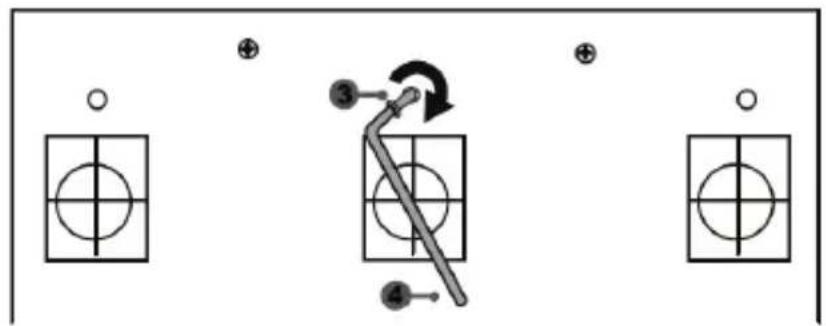
flowchart
graph TD
    A["○"] --> B["○"]
    C["⊕"] --> D["○"]
    E["●"] --> F["○"]
    G["⊕"] --> H["○"]
    I["●"] --> J["○"]
    K["●"] --> L["○"]
    M["●"] --> N["○"]
    O["●"] --> P["○"]
    Q["●"] --> R["○"]
    S["●"] --> T["○"]
    U["●"] --> V["○"]
    W["●"] --> X["○"]
    Y["●"] --> Z["○"]
De "CONICAL RUBBER BRAKE" mod is nu gemonteerd
natural_image
Mechanical component diagram showing a valve mechanism with directional arrows (no text or symbols)natural_image
Symbol of a trash bin crossed with no text or numbers, representing waste sorting or disposal (no text present)www.thrustmaster.com
T-GT
Manuale d'uso

natural_image
Technical line drawing of a steering wheel and control panel assembly (no text or symbols)ATTENZIONE:
natural_image
Diagram of a mechanical device with rotating arms and central hub, enclosed in a circular frame (no text or symbols)


natural_image
Technical line drawing showing a device component before and after assembly, with no visible text or symbols.natural_image
Technical line drawing of a mechanical assembly with no visible text or symbols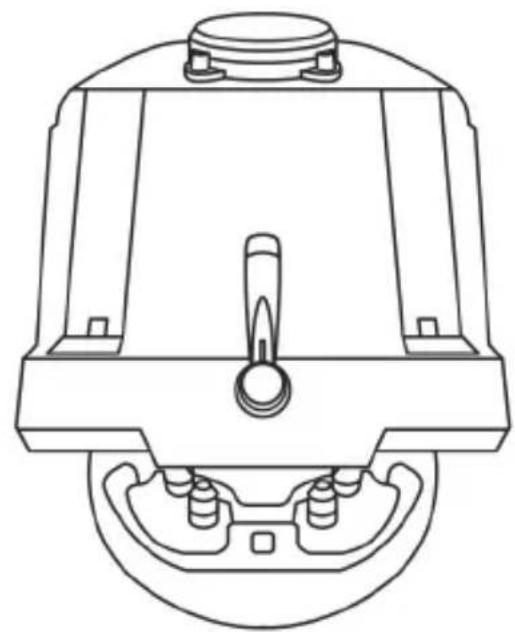
natural_image
Technical line drawing of a mechanical component with no visible text or symbolsATTENZIONE:
natural_image
Line drawing of a device with three speakers on top (no text or symbols)CARATTERISTICHE TECNICHE

natural_image
Diagram showing two mechanical components with a downward arrow indicating motion or change (no text or symbols)Posizione bassa
natural_image
Diagram showing two identical mechanical components with a central arrow indicating upward motion (no text or symbols)Posizione alta
natural_image
Diagram showing two mechanical components with directional arrows indicating movement or force (no text or symbols)natural_image
Two identical mechanical or electrical components with vertical bars and circular holes, shown side by side (no text or symbols)natural_image
Diagram showing two mechanical components with arrows indicating direction of movement (no text or symbols)Posizione a destra
natural_image
Diagram of a ladder structure with an arrow indicating upward motion (no text or symbols)natural_image
Diagram of a mechanical structure with an arrow indicating direction, no text or symbols present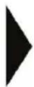

natural_image
Mechanical component diagram showing a valve mechanism with a rotating knob (no text or symbols)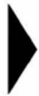

natural_image
Technical line drawing of a mechanical clamp or bracket assembly (no text or symbols)natural_image
Diagram showing a hand holding a tool inside a circular frame with an oil pumpjack, no text or symbols present.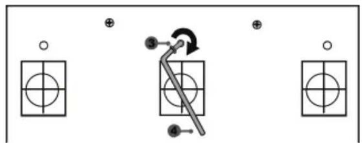
natural_image
Mechanical component diagram showing a valve mechanism with directional arrows (no text or labels)COPYRIGHT
natural_image
Symbol of a trash bin crossed with a diagonal line and a black rectangle below (no text or labels)www.thrustmaster.com
T-GT
Manual del usuario

natural_image
Technical line drawing of a steering wheel and control panel assembly (no text or symbols)ADVERTENCIA:
natural_image
Diagram of a mechanical assembly with rotating components and directional arrows (no text or symbols)


natural_image
Diagram showing a device component before and after transformation, with no visible text or symbols.natural_image
Technical line drawing of a mechanical assembly with no visible text or symbols
natural_image
Technical line drawing of a mechanical component with no visible text or symbolsATENCIÓN:
natural_image
Line drawing of a device with three speakers on top (no text or symbols)CARACTERÍSTICAS TÉCNICAS

natural_image
Diagram showing two mechanical components with a downward arrow indicating transformation or change (no text or symbols present)Posición baja

natural_image
Diagram showing two identical mechanical components with a directional arrow, no text or symbols presentPosición alta
natural_image
Technical diagram showing two mechanical components with arrows indicating direction (no text or symbols)Posición izquierda
natural_image
Two identical mechanical components with circular holes, mounted on support poles (no text or symbols visible)natural_image
Diagram showing two mechanical components with arrows indicating motion or assembly (no text or symbols)Posición derecha
natural_image
Diagram of a mechanical structure with triangular supports and a downward arrow indicating force or motion (no text or symbols)natural_image
Diagram of a mechanical structure with an arrow indicating direction, no text or symbols present
natural_image
Mechanical component diagram showing a valve mechanism with a rotating knob (no text or symbols)natural_image
Diagram showing a mechanical device with a magnified view of three labeled components (no text or symbols present)
natural_image
Technical line drawing of a mechanical clamp or bracket assembly (no text or symbols)natural_image
Illustration of a hand using a tool to lift a mechanical component inside a circular frame, with a black arrow indicating rotation (no text or symbols)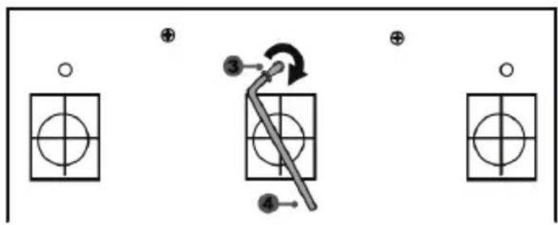
flowchart
graph TD
    A["Grid Box 1"] --> B["Central Tool"]
    C["Grid Box 2"] --> B
    D["Grid Box 3"] --> B
    E["Grid Box 4"] --> B
    B --> F["Arrow to Center"]
    style B fill:#f9f,stroke:#333,stroke-width:2px
natural_image
Mechanical component diagram showing a valve mechanism with directional arrows (no text or labels)natural_image
Symbol of a trash bin crossed with no visible text or labelswww.thrustmaster.com
T-GT
Manual do Utilizador
natural_image
Technical line drawing of a steering wheel and motor control panel (no text or symbols)ATENÇÃO:
natural_image
Diagram of a mechanical assembly with rotating components and directional arrows (no text or symbols)NUNCA

NUNCA


natural_image
Diagram showing a device component before and after transformation, with no visible text or symbols.natural_image
Technical line drawing of a mechanical device with internal components and mounting feet (no text or symbols)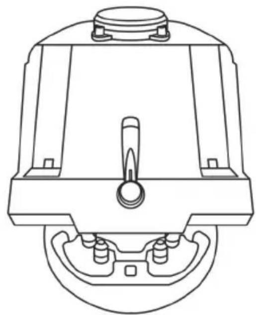
natural_image
Technical line drawing of a mechanical component with no visible text or symbolsATENÇÃO:
natural_image
Line drawing of a device with three speakers on top (no text or symbols)CARACTERÍSTICAS TÉCNICAS

FIXAR O CONJUNTO DE PEDAIS A UM COCKPIT
- Fixe o conjunto de pedais utilizando as pequenas roscas de parafusos situadas na parte inferior do conjunto de pedais.
- Enrosque dois parafusos M6 (não incluídos) na chapa de apoio do conjunto de pedais e nas duas pequenas roscas de parafusos situadas na parte inferior do conjunto de pedais.
natural_image
Diagram showing two identical mechanical components with a downward arrow indicating a transformation or alignment (no text or symbols present)Posição baixa

natural_image
Diagram showing two identical mechanical components with a directional arrow, no text or symbols presentPosição alta
natural_image
Diagram showing two mechanical components with arrows indicating direction, no text or symbols presentPosição à esquerda

natural_image
Two identical mechanical components with vertical bars and circular holes, mounted on support frames (no text or symbols)natural_image
Diagram showing two mechanical components with arrows indicating motion or assembly (no text or symbols)Posição à direita
natural_image
Diagram of a mechanical structure with triangular supports and a downward arrow indicating force or motion (no text or symbols)natural_image
Diagram of a mechanical structure with an arrow indicating direction, no text or symbols presentnatural_image
Illustration of an oil pumpjack inside a circular frame with a hand holding a tool, no text or symbols present.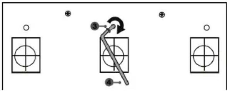
flowchart
graph TD
    A["Step ③"] --> B["Arrow to Step ④"]
    B --> C["Step ④"]
    D["Step ④"] --> E["Step ③"]
    F["Step ③"] --> G["Step ④"]
    H["Step ④"] --> I["Step ③"]
natural_image
Mechanical component diagram showing a valve mechanism with directional arrows (no text or symbols)natural_image
Simple line drawing of a trash bin with no text or symbolswww.thrustmaster.com
T-GT
natural_image
Technical line drawing of a steering wheel and control panel assembly (no text or symbols)ВНИМАНИЕ!
natural_image
Diagram of a mechanical assembly with rotating components and directional arrows (no text or symbols)НЕЛЬЗЯ
НЕЛЬЗЯ


natural_image
Diagram showing a device component before and after transformation, with no visible text or symbols.natural_image
Technical line drawing of a mechanical assembly with no visible text or symbols
natural_image
Technical line drawing of a mechanical component with no visible text or symbolsВНИМАНИЕ!
natural_image
Line drawing of a device with three speakers on top (no text or symbols)natural_image
Diagram showing two mechanical components with a downward arrow indicating motion or change (no text or symbols)Нижнее положение
natural_image
Diagram showing two identical mechanical components with a central arrow indicating upward motion (no text or symbols)Высокое положение
natural_image
Technical diagram showing two mechanical components with arrows indicating direction (no text or symbols)Левое положение
natural_image
Two identical mechanical or electrical components with vertical bars and circular holes, mounted on a stand (no text or symbols visible)natural_image
Diagram showing two mechanical components with arrows indicating motion or assembly (no text or symbols)Правое положение
natural_image
Diagram of a mechanical structure with a triangular frame and an arrow indicating upward motion (no text or symbols)Угол наклона меньше
natural_image
Diagram of a mechanical structure with an arrow indicating direction, no text or symbols presentnatural_image
Illustration of an oil pumpjack inside a circular frame with a hand holding a tool, no text or symbols present.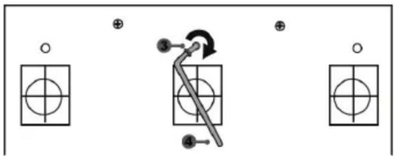
flowchart
graph TD
    A["○"] --> B["○"]
    C["⊕"] --> D["○"]
    E["●"] --> F["○"]
    G["●"] --> H["○"]
    I["●"] --> J["○"]
    K["●"] --> L["○"]
    M["●"] --> N["○"]
    O["●"] --> P["○"]
    Q["●"] --> R["○"]
    S["●"] --> T["○"]
    U["●"] --> V["○"]
    W["●"] --> X["○"]
    Y["●"] --> Z["○"]
    style A fill:#fff,stroke:#000
    style C fill:#fff,stroke:#000
    style E fill:#fff,stroke:#000
    style G fill:#fff,stroke:#000
    style I fill:#fff,stroke:#000
    style M fill:#fff,stroke:#000
    style Q fill:#fff,stroke:#000
    style K fill:#fff,stroke:#000
    style U fill:#fff,stroke:#000
    style V fill:#fff,stroke:#000
    style W fill:#fff,stroke:#000
    style X fill:#fff,stroke:#000
    style Y fill:#fff,stroke:#000
    style Z fill:#fff,stroke:#000
Модуль CONICAL RUBBER BRAKE mod установлен!
natural_image
Mechanical component diagram showing a valve mechanism with directional arrows (no text or labels)АВТОРСКИЕ ПРАВА
www.thrustmaster.com

EAC
immersion.
T-GT
Εγχειρίδιο χρήσης

natural_image
Technical line drawing of a steering wheel and motor control panel (no text or symbols)ΠΡΟΕΙΔΟΠΟΙΗΣΗ:
natural_image
Technical diagram of a mechanical assembly with rotating components and housing (no text or labels)


natural_image
Diagram showing a device component before and after transformation, with no visible text or symbols.natural_image
Technical line drawing of a mechanical assembly with no visible text or symbols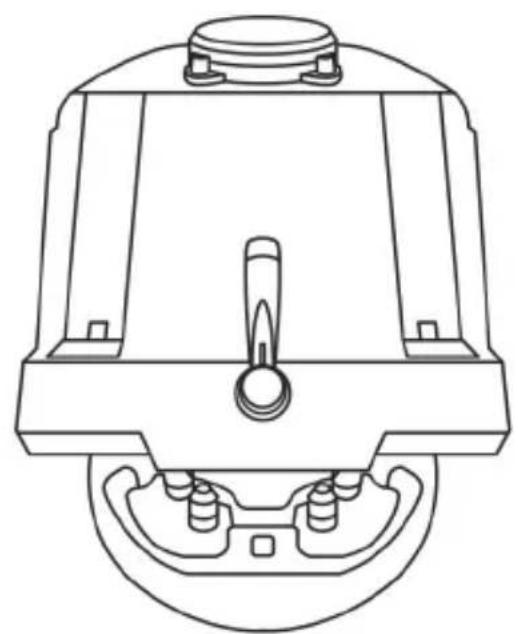
natural_image
Technical line drawing of a mechanical component with no visible text or symbolsΠΡΟΕΙΔΟΠΟΙΗΣΗ:
natural_image
Line drawing of a device with three speakers on top (no text or symbols)TEXNIKA XAPAKTHPIΣTIKA

natural_image
Diagram showing two mechanical components with a downward arrow indicating motion or change (no text or symbols present)Χαμηλή θέση

natural_image
Diagram showing two identical mechanical components with a central arrow indicating direction (no text or symbols)Υψηλή θέση
natural_image
Diagram showing two mechanical components with arrows indicating direction, no text or symbols presentΑριστερά
natural_image
Two identical mechanical components with vertical bars and circular holes, mounted on support poles (no text or symbols)Κέντρο (προεπιλογή)
natural_image
Diagram showing two mechanical components with arrows indicating direction of movement (no text or symbols)Δεξιά
natural_image
Diagram of a mechanical structure with a triangular frame and an arrow indicating upward motion (no text or symbols)natural_image
Diagram of a mechanical structure with an arrow indicating direction, no text or symbols presentnatural_image
Diagram showing a hand holding a tool with a compass and a circular arrow, no text or symbols present.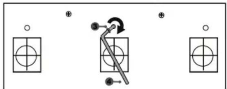
natural_image
Mechanical component diagram showing a valve mechanism with directional arrows (no text or symbols)natural_image
Simple line drawing of a trash bin with cross-bracing and a black rectangle below (no text or symbols)www.thrustmaster.com
natural_image
Technical line drawing of a steering wheel and motor control panel (no text or symbols)UYARI:
natural_image
Technical diagram of a mechanical assembly with rotating components (no text or labels)


natural_image
Technical line drawing showing a device component before and after assembly, with no visible text or symbols.natural_image
Technical line drawing of a mechanical assembly with no visible text or symbols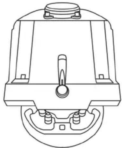
natural_image
Technical line drawing of a mechanical component with no visible text or symbolsUYARI:
T-GT EDITION PEDAL SETI

natural_image
Line drawing of a device with three speakers on top (no text or symbols)TEKNİK ÖZELLİKLER
natural_image
Diagram showing two mechanical components with a downward arrow indicating motion or change (no text or symbols present)Alçak pozisyon
natural_image
Diagram showing two identical mechanical components with a central arrow indicating upward motion (no text or symbols)Yüksek pozisyon
natural_image
Diagram showing two mechanical components with arrows indicating direction, no text or symbols presentSol pozisyon
natural_image
Two identical mechanical or electrical components with vertical bars and circular holes, mounted on support poles (no text or symbols visible)natural_image
Diagram showing two mechanical components with arrows indicating direction of movement (no text or symbols)Sağ pozisyon
natural_image
Diagram of a mechanical structure with a triangular frame and an upward arrow, no text or symbols presentAz eğimli pozisyon
natural_image
Diagram of a mechanical structure with an arrow indicating direction, no text or symbols presentnatural_image
Diagram showing a hand holding a tool inside a circular frame with an arrow indicating rotation (no text or symbols)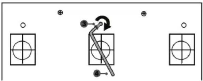
"CONICAL RUBBER BRAKE" mod şimdi monteli!
natural_image
Mechanical component diagram showing a valve mechanism with directional arrows (no text or labels)natural_image
Three black icons: a lowercase 'i' in a circle, an envelope, and a telephone handset (no text or symbols)TELİF HAKKI
www.thrustmaster.com
natural_image
Technical line drawing of a steering wheel and control panel assembly (no text or symbols)OSTRZEŻENIE:
natural_image
Diagram of a mechanical assembly with rotating components and directional arrows (no text or symbols)NIGDY

NIGDY

flowchart
graph TD
    A["Wheel Hub"] --> B["Assembly Gear Component"]
    B --> C["Motor Assembly"]
    C --> D["Final Gear Component with Arrow indicating motion"]

natural_image
Diagram showing a device component before and after transformation, with no visible text or symbols.natural_image
Technical line drawing of a mechanical assembly with no visible text or symbols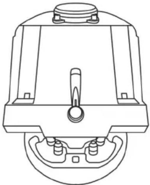
natural_image
Technical line drawing of a mechanical component with no visible text or symbolsUWAGA:
natural_image
Line drawing of a device with three speakers on top (no text or symbols)ELEMENTY

natural_image
Diagram showing two mechanical components with a downward arrow indicating motion or change (no text or symbols)natural_image
Diagram showing two identical mechanical components with a central arrow indicating direction (no text or symbols)Położenie wysokie
natural_image
Diagram showing two mechanical components with arrows indicating direction, no text or symbols presentPołożenie lewe
natural_image
Two identical mechanical components with circular holes, mounted on support frames (no text or symbols visible)natural_image
Diagram showing two mechanical components with arrows indicating direction of movement (no text or symbols)Położenie prawe
natural_image
Diagram of a mechanical structure with triangular supports and a directional arrow (no text or symbols)Mniejsze nachylenie
natural_image
Diagram of a mechanical structure with an arrow indicating direction, no text or symbols present
natural_image
Mechanical component diagram showing a valve mechanism with a rotating knob (no text or symbols)
natural_image
Technical line drawing of a mechanical clamp or bracket assembly (no text or symbols)natural_image
Illustration of a hand using a tool to measure a circular component with an arrow, no text or symbols present.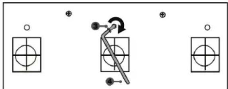
natural_image
Mechanical component diagram showing a valve mechanism with directional arrows (no text or symbols)PRAWA AUTORSKIE
natural_image
Symbol of a trash bin with no visible text or labelswww.thrustmaster.com
T-GT
دليل المستخدم

natural_image
Technical line drawing of a steering wheel and control panel assembly (no text or symbols)natural_image
Pure diagram of a symmetrical arch structure with two circular ends and a central vertical line, no text or symbols present.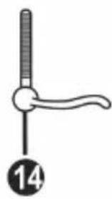
natural_image
Simple line drawing of a medical or surgical tool with a handle and circular label (no text or symbols)OPTIONS 8
PS alzr 9
10 إلزر مؤشر ضوء
أحمر/أخضر
OTHER/GT. مفتاح USB 11
natural_image
Diagram of a mechanical device with rotating arms and housing (no text or symbols)مطلّق

مطلقا


natural_image
Diagram showing a device component before and after transformation, with no visible text or symbols.natural_image
Line drawing of a device with three speakers on top (no text or symbols)الميزات التقنية
natural_image
Diagram showing two mechanical components with a downward arrow indicating motion or change (no text or symbols)الوضع المنخفض
natural_image
Diagram showing two identical mechanical components with a central arrow indicating upward motion (no text or symbols)الوضع المرتفع
flowchart
graph TD
    A["Start"] --> B["Left side: Internal components with arrows indicating movement"]
    B --> C["Right side: In the main surface with arrows indicating movement"]
    C --> D["Left side: Internal components with arrows indicating movement"]
    D --> E["Right side: Internal components with arrows indicating movement"]
    style A fill:#f9f,stroke:#333
    style B fill:#ccf,stroke:#333
    style C fill:#cfc,stroke:#333
    style D fill:#fcc,stroke:#333
    style E fill:#ffc,stroke:#333

natural_image
Mechanical component diagram showing a rotating assembly with a bolt and nut (no text or symbols)

natural_image
Technical line drawing of a mechanical clamp or bracket assembly (no text or symbols)natural_image
Illustration of an oil pumpjack inside a circular frame with a hand holding a tool, no text or symbols present.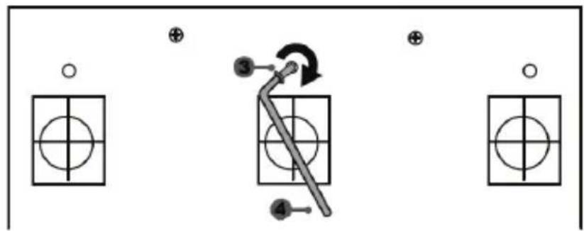
flowchart
graph TD
    A["○"] --> B["○"]
    C["⊕"] --> D["○"]
    E["●"] --> F["○"]
    G["③"] --> H["←"]
    I["④"] --> J["←"]
    K["⊕"] --> L["○"]
natural_image
Mechanical component diagram showing a valve mechanism with directional arrows (no text or labels)www.thrustmaster.com
natural_image
Technical line drawing of a steering wheel and control panel assembly (no text or symbols)WARNING:
To ensure that your T-GT racing wheel functions correctly with games, you may be required to install the game's automatic updates (available when your system is connected to the Internet).
TECHNICAL FEATURES
1 T-GT base
2 T-GT wheel
3 2 sequential paddle shifters (up & down)
4 Directional buttons
5 4 rotary selectors with Push function (compatible with the PS4 ^TM system in GT mode and on PC)
6 2 mini-sticks (compatible with the PS4 ^TM system in GT mode and on PC)
7 SHARE button
8 OPTIONS button
9 PS button
10 MODE button + red/green indicator light
11 Built-in USB sliding switch: OTHER / GT
12 Large threaded hole (for attachment system and fastening screw)
13 Attachment system
14 Metal fastening screw

15 Thrustmaster Quick Release
16 T-DFB effects system (only compatible with the PS4 ^TM system in GT mode)
17 Connector for T-TURBO power supply
18 Connector for removable USB cable
19 Connector for pedal set
20 Connector for TH8A shifter (shifter sold separately)
21 T-TURBO power supply
22 Power supply cable
23 Removable USB cable
PLUGGING THE WHEEL INTO AN ELECTRICAL OUTLET: PLEASE READ CAREFULLY!

Never plug the T-TURBO power supply into an electrical outlet with a different voltage! The
T-TURBO power supply's voltage is indicated on the label located above the female connector for the power supply cable.

Never connect a power supply other than the T-TURBO power supply to the T-GT base,
even if the connector is compatible! For example, never connect the power adapter for the T500 RS wheel to the T-GT base.
WARNING
Before using this product, please read this manual carefully and save it for later reference.

Warning – Electrical shock
* Keep the product in a dry location and do not expose it to dust or sunlight.
* Do not twist or pull on the connectors and cables.
* Do not spill any liquid on the product or its connectors.
* Do not short-circuit the product.
* Never dismantle the product; do not throw it onto a fire and do not expose it to high temperatures.
* Do not use a power supply cable other than the one provided with your racing wheel.
* Do not use the power supply cable if the cable or its connectors are damaged, split or broken.
* Make sure that the power supply cable is properly plugged into an electrical outlet, and properly connected to the connector at the rear of the racing wheel's base.
* Do not open up the racing wheel: there are no user-serviceable parts inside. Any repairs must be carried out by the manufacturer, its authorized representative or a qualified technician.
* Only use attachment systems/accessories specified by the manufacturer.
* If the racing wheel is operating abnormally (if it is emitting any abnormal sounds, heat or odors), stop using it immediately, unplug the power supply cable from the electrical outlet and disconnect the other cables.
* If you will not be using the racing wheel for an extended period of time, unplug its power supply cable from the electrical outlet.
* The electrical outlet must be located near the equipment and must be easily accessible.

Air vents
Make sure not to block any of the air vents on the racing wheel's base. For optimal ventilation, make sure to do the following:
* Position the wheel's base at least 10c m away from any wall surfaces.
* Do not place the base in any tight spaces.
* Do not cover the base.
* Do not let any dust build up on the air vents.

For safety reasons, never use the pedal set with bare feet or while wearing only socks on your feet.
THRUSTMASTER® DISCLAIMS ALL RESPONSIBILITY IN THE EVENT OF INJURY RESULTING FROM USE OF THE PEDAL SET WITHOUT SHOES.

Warning – Injuries due to Force Feedback and repeated movements
Playing with a Force Feedback racing wheel may cause muscle or joint pain. To avoid any problems:
* Avoid lengthy gaming periods.
* Take 10 to 15 minute breaks after each hour of play.
* If you feel any fatigue or pain in your hands, wrists, arms, feet or legs, stop playing and rest for a few hours before you start playing again.

Warning – Injuries due to Force Feedback and repeated movements (continued)
* If the symptoms or pain indicated persist when you start playing again, stop playing and consult your doctor.
* Keep out of children's reach.
* During gameplay, always leave both hands correctly positioned on the wheel without completely letting go.
* During gameplay, never place your hands or your fingers under the pedals or anywhere near the pedal set.
* During calibration and gameplay, never place your hand or your arm through the openings in the racing wheel.
* Make sure that the racing wheel's base is properly secured, as per this manual's instructions.

Product to be handled only by users 16 years of age or older
HEAVY PRODUCT

Be careful not to drop the product on yourself or on anyone else!
ALWAYS
natural_image
Diagram of a mechanical assembly with rotating components and directional arrows (no text or symbols)NEVER
NEVER


Warning – Pedal set pinch hazard when playing
* Keep the pedal set out of children's reach.
* During gameplay, never place your fingers on or anywhere near the sides of the pedals.
* During gameplay, never place your fingers on or anywhere near the pedal's rear base.
* During gameplay, never place your fingers on or anywhere near the pedal's front base.


Warning – Pedal set pinch hazard when not playing
* Store the pedal set in a safe place, and keep it out of children's reach.
UPDATING YOUR RACING WHEEL'S FIRMWARE
The firmware included in your racing wheel's base can be updated to a more recent version featuring product enhancements.
To display the firmware version that your racing wheel is currently using and update it if required: on PC, visit http://support.thrustmaster.com. Click Racing Wheels / T-GT, then select Firmware and follow the instructions describing the download and installation procedure.
Important note:
On PC, the USB sliding switch (11) on the racing wheel's base must always be set to the "OTHER" position.
INSTALLING THE WHEEL ON ITS BASE
Align the connector positions using the arrows:
Base (1) connector: Arrow pointing upwards
Racing wheel (2) connector: Arrow pointing upwards
Once the connectors are correctly positioned, simply rotate the Thrustmaster Quick Release (15) device's ring counterclockwise, while holding the racing wheel (2) in position.
Then, tighten the ring as much as you can: to do so, hold the ring in position and rotate the racing wheel clockwise.

flowchart
graph TD
    A["Wheel rim"] --> B["Target"]
    B --> C["Motor Component"]
    C --> D["Assembly"]
    D --> E["Motor Component"]
Once you have installed the wheel, rotate it 180^ (when facing the wheel, the GT logo should be upside down) to access the small attachment screw located on the ring of the Thrustmaster Quick Release (15) device. Use a large Phillips screwdriver to tighten the small attachment screw (do not use excessive force), turning it clockwise.
When using a Philips screwdriver, ensure NOT to use excessive force when tightening the small attachment screw!
Stop turning the screw as soon as you feel some resistance.
ATTACHING THE RACING WHEEL
Attaching the racing wheel's base to a cockpit

24 2 M6-type hexagon head/Phillips-head bolts
25 2 washers
26 2 mounting discs (metal on one side, and textured rubber on the other)


natural_image
Diagram showing a device component before and after transformation, with no visible text or symbols.- Position the washers (25) on the metal sides of the mounting discs (26), and insert the M6-type hexagon head/Phillips-head bolts (24).
- Place the racing wheel's base on the cockpit shelf.
- Using a 10 mm wrench key or a Phillips-head screwdriver, screw the cockpit mounting kit into the cockpit shelf and into the 2 small screw threads located on the underside of the wheel.
ATTENTION:
- Do not remove the foam pads located on the underside of the racing wheel's base! The foam pads amplify the effects of the T-DFB system when the wheel is attached.
- The textured rubber side of the mounting discs (26) must imperatively be positioned facing the cockpit shelf = never position the metal side facing the cockpit shelf.
Attaching the racing wheel to a table or a desktop
- Place the racing wheel on a table or any other horizontal, flat and stable surface.
- Insert the fastening screw (14) in the attachment system (13), then tighten the device by turning the screw anticlockwise, so that it feeds into the large threaded hole (12) located beneath the racing wheel, until the wheel is perfectly stable.
ALWAYS NEVER
natural_image
Technical line drawing of a mechanical assembly with no visible text or symbols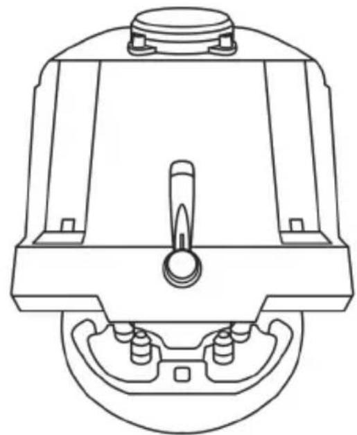
natural_image
Technical line drawing of a mechanical component with no visible text or symbolsWARNING:
- Never tighten the screw alone, without the attachment system in place (this could damage the racing wheel).
- Do not remove the foam pads located on the underside of the racing wheel's base! The foam pads amplify the effects of the T-DFB system when the wheel is attached.
| ATTACHMENT / REMOVAL | DIRECTION |
| To tighten:Turn the screw anticlockwise | 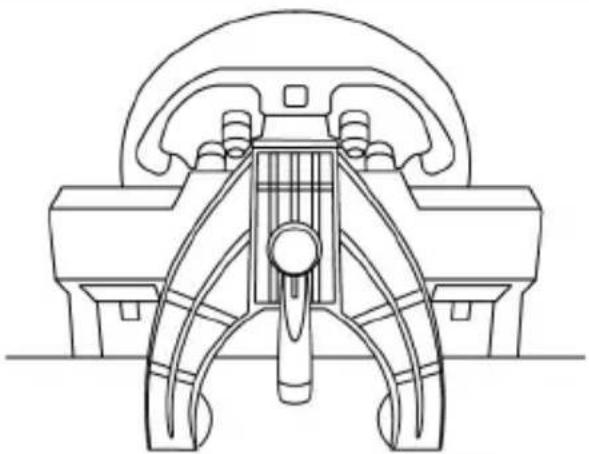 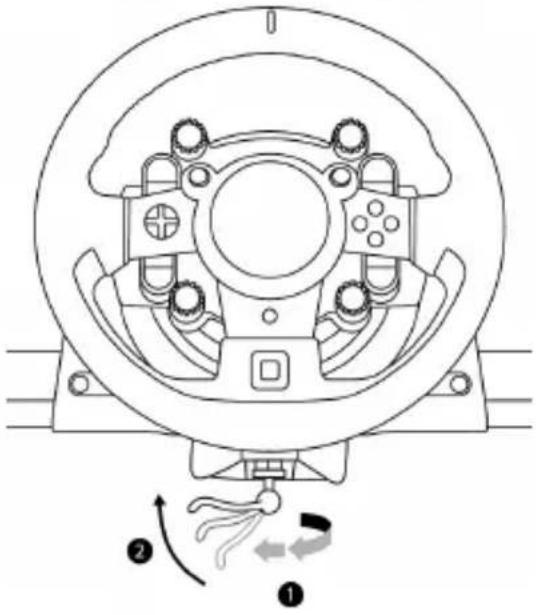 |
| To release:Turn the screw clockwise | 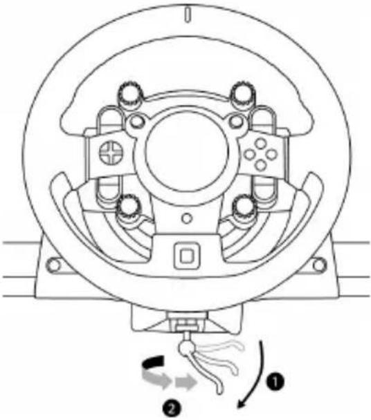 |
SETTING UP THE RACING WHEEL FOR PLAYSTATION®4
- Connect the pedal set to its connector (19) located at the rear of the racing wheel's base.
- Connect the T-TURBO power supply (21) to its connector (17).
- Connect the power supply cable (22) to the T-TURBO power supply, and plug the cable into an electrical outlet with the same voltage.
- Set the USB sliding switch (11) to the "OTHER" or "GT" position, depending on the PS4™ game you are using.
- Connect the removable USB cable (23) to its connector (18) and to one of the USB ports on the PS4 ^™ system.
- Once your PS4 ^TM system is powered on, your racing wheel will calibrate itself.
- Press the PS button (9) on the racing wheel, and log in to your Sony Entertainment Network account in order for your wheel to be functional.
You are now ready to play!
Important notes:
- Don't forget to press the PS button (9) on the racing wheel, in order for your wheel to be functional.
- The USB sliding switch (11) on the wheel's base must always be set to the proper position ("OTHER" or "GT") before connecting the racing wheel's USB cable to your system.
To change the sliding switch's position: disconnect the USB cable, and then set the switch to the appropriate position before reconnecting the USB cable to the system. - The list of PlayStation®4 games compatible with the T-GT (along with the required position for the USB sliding switch (11) according to the game you are using) is available here: http://support.thrustmaster.com (in the Racing Wheels/T-GT section). This list is updated regularly.
USB SLIDING SWITCH (11) IN THE "OTHER" POSITION
FOR PS4™ GAMES APART FROM GT SPORT
When the USB sliding switch (11) is set to the "OTHER" position:
* The wheel is recognized in most games as a T300 RS wheel.
* The 4 rotary selectors with Push function (5) are not functional.
* The 2 mini-sticks (6) are not functional.
* The Force Feedback system is functional, but the T-DFB effects system (16) is not.
USB SLIDING SWITCH (11) IN THE "GT" POSITION
FOR THE GAME GT SPORT (AND OTHER FUTURE GT GAMES)
When the USB sliding switch (11) is set to the "GT" position:
* The wheel is recognized as a T-GT wheel.
* The 4 rotary selectors with Push function (5) are functional.
* The 2 mini-sticks (6) are functional.
* The Force Feedback system, and the T-DFB effects system (16), are both functional at the same time. In the GT Sport game's options, the power level of each system can be adjusted independently.
SETTING UP THE RACING WHEEL FOR PC
Important notes:
- On PC, the USB sliding switch (11) on the racing wheel's base must always be set to the OTHER position.
- On PC, the 2 mini-sticks (6) are functional.
- On PC, the 4 rotary selectors with Push function (5) are functional.
-
On PC, the Force Feedback system is functional, but the T-DFB effects system (16) is not.
-
Go to http://support.thrustmaster.com to download the drivers and the force feedback software for PC. Click Wheels / T-GT, then select Drivers.
- Once the download is complete, launch the installation, and follow the on-screen instructions to connect the wheel's USB plug to your computer and complete the installation.
- Once the installation is complete, click Finish and restart your computer.
- Select Start / All Programs / Thrustmaster / FFB Racing Wheel / Control Panel to open the Game Controllers window.
The Game Controllers window displays the racing wheel's name Thrustmaster T-GT Racing Wheel with the status OK.
- Click Properties to configure your wheel in the T-GT control panel:
- Test Input tab: allows to test and view the 25 action buttons, 4 rotary selectors with Push function, directional buttons, wheel axes, 2 mini-sticks axes, pedals axes, and to adjust the wheel's rotation angle in your PC games.
- Test Forces tab: allows to test 12 force feedback effects.
- Gain Settings tab: allows to adjust the power of the force feedback effects in your PC games.
You are now ready to play!
General notes:
- On PC, click OK to close the Game Controllers window before launching the game.
- On PC, the adjustments made in the Game Controllers window will only be saved on your computer (hence they will have no effect on the PlayStation ^® 4 system).
- Your wheel's firmware version is displayed in the upper right-hand corner of the T-GT control panel tabs.
AUTOMATIC RACING WHEEL AND PEDAL SET CALIBRATION
The wheel automatically self-calibrates when you plug the racing wheel into an electrical outlet and connect the racing wheel's USB connector to the system.
During this phase, the racing wheel will rotate quickly towards the left and the right, covering a 1080 degree angle, before stopping at the center.

WARNING:
Never touch the racing wheel during the self-calibration phase!
(This could result in improper calibration and/or personal injuries.)
AUTOMATIC CALIBRATION OF THE PEDAL SET
Never connect the pedal set to the racing wheel's base (or disconnect it from the base) when it is connected to the system or during gameplay (this could result in improper calibration).
Always connect the pedal set before connecting the racing wheel to the system.
Once the racing wheel's calibration is complete and the game has been started, the pedals are automatically calibrated after a few presses.

WARNING:
Never press the pedals during the racing wheel's self-calibration phase or while a game is loading!
(This could result in improper calibration.)
If your racing wheel and/or pedal set do not function correctly, or if they seem to be improperly calibrated:
Power off your system and completely disconnect the racing wheel. Then reconnect all cables (including the power supply cable and the pedal set), and restart your system and your game.
INTERNAL COOLING SYSTEM FOR THE WHEEL'S BASE
The internal cooling system for the wheel's base starts working when the wheel is powered on, and only switches off when the wheel's USB port is no longer powered.
MODE BUTTON AND INDICATOR LIGHT (10)
MODE button for the pedal set
You can electronically swap the accelerator and clutch pedals.
To do so, simply press the MODE button (10) for 2 seconds.
The racing wheel's internal memory stores whether the pedals have been swapped around or not.
| GAS AND CLUTCH PEDALS | Color of the MODE indicator light (10) |
| NORMAL | RED |
| SWAPPED AROUND | GREEN |
Other information regarding the MODE button
To learn more about the MODE button and indicator light, please visit
http://support.thrustmaster.com. Click Racing Wheels / T-GT, and then select Manual or FAQ.
HELP FILES AND FAQs (NOT INCLUDED IN THIS MANUAL)
Please visit http://support.thrustmaster.com. Click Racing Wheels / T-GT, and then select Manual or FAQ.
T-GT EDITION PEDAL SET

natural_image
Line drawing of a device with three speakers on top (no text or symbols)TECHNICAL FEATURES
1 Metal support for conical stop (not installed by default)
2 Conical stop
3 Attachment screw for metal support
4 2.5 mm Allen key (included)
5 Position adjustment nut for conical stop

6 Metal pedal arm
7 Plastic head support
8 Metal pedal head
WARNING
Before using this product, be sure to read these instructions carefully and save them for future reference.

For safety reasons, never use the pedal set with bare feet or while wearing only socks on your feet.
THRUSTMASTER® DISCLAIMS ALL RESPONSIBILITY IN THE EVENT OF INJURY RESULTING FROM USE OF THE PEDAL SET WITHOUT SHOES.

Warning – Pedal set pinching hazard during gaming sessions
* Keep the pedal set out of the reach of children.
* During gaming sessions, never place your fingers or thumbs on or near the sides of the pedals.
* During gaming sessions, never place your fingers or thumbs on or near the rear base of the pedals.
* During gaming sessions, never place your fingers or thumbs on or near the front base of the pedals.

AUTOMATIC CALIBRATION OF PEDALS

IMPORTANT:
- Never connect or disconnect the pedal set from the base of the wheel when the wheel is connected to a PS4 ^™ system or to a PC, or during gaming sessions, to avoid calibration problems.
= Always connect the pedal set to the wheel before connecting the wheel to a PS4 ^TM system or to a PC. - Once the wheel has self-calibrated and the game has started, the pedals automatically calibrate themselves after being pressed a few times.
- Never press on the pedals when the wheel is self-calibrating or when your game is starting up, to avoid calibration problems.
- If the pedals are not functioning correctly or appear to be improperly calibrated, power off your system, completely disconnect your wheel, then reconnect all of the cables (including the power supply cable and the pedal set cable), power the system back on and restart your game.
ATTACHING THE PEDAL SET TO A COCKPIT
- Attach the pedal set using the small screw threads located on the underside of the pedal set.
- Screw two M6 screws (not included) into the cockpit's pedal support plate and into the two small screw threads located on the underside of the pedal set.
Important: The length of the two M6 screws must not exceed the thickness of the cockpit's pedal support plate plus an additional 10 mm, to avoid damaging the pedal set's internal components.
ADJUSTING THE PEDAL SET
Each of the three pedals includes:
- A metal head (8) with multiple perforations (nine for the accelerator – two for the brake – six for the clutch).
- A plastic head support (7) (placed between the head and the arm) with four perforations.
- A metal pedal arm (6) with four perforations.

ATTENTION: To avoid any calibration problems, be sure to always disconnect your wheel's USB cable from the PS4™ system before making any adjustments to your pedal set.
Adjusting the HEIGHT of the 3 pedals
- Using the included 2.5 mm Allen key (4), unscrew the two screws holding the metal head (8) and its support (7) in place.
- Select your preferred height position, then replace and re-tighten the screws so that the metal head (8) and its support (7) are held firmly in place.
Examples illustrating the accelerator pedal:
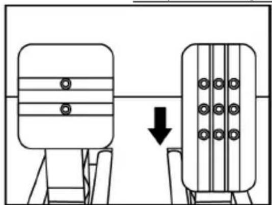
natural_image
Diagram showing two mechanical components with a downward arrow indicating motion or change (no text or symbols)Low position

natural_image
Diagram showing two identical mechanical components with a directional arrow, no text or symbols presentHigh position
Adjusting the SPACING of the accelerator pedal and the clutch pedal
- Using the included 2.5 mm Allen key (4), unscrew the two screws holding the metal head (8) and its support (7) in place.
- Select your preferred position (to the left, centered, or to the right), then replace and re-tighten the screws so that the metal head (8) and its support (7) are held firmly in place.
Examples illustrating the clutch pedal:

natural_image
Diagram showing two mechanical components with directional arrows indicating movement or force (no text or symbols)Left position
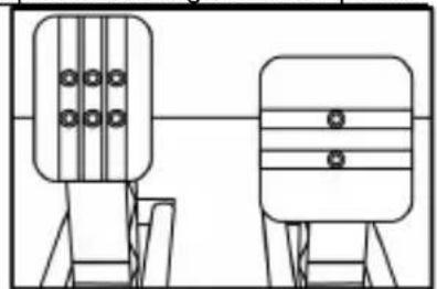
natural_image
Two identical mechanical components with vertical bars and circular holes, mounted on support frames (no text or symbols)Centered position (default)

natural_image
Diagram showing two mechanical components with arrows indicating motion or transformation (no text or symbols)Right position
Number of possible spacing positions per pedal:
- Three for accelerator pedal
- Three for clutch pedal
Adjusting the INCLINATION of the 3 pedals
- Using the included 2.5 mm Allen key (4), unscrew the two screws holding the metal head (8) and its support (7) in place.
- Turn the plastic head support (7) 180^ , then replace and re-tighten the screws so that the metal head (8) and its support (7) are held firmly in place.
Examples illustrating the accelerator pedal:

natural_image
Diagram of a mechanical structure with a triangular frame and an arrow indicating direction (no text or symbols)Less inclined position
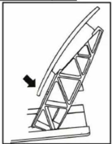
natural_image
Diagram of a mechanical structure with an arrow indicating direction, no text or symbols presentMore inclined position (default)
Number of possible inclination positions per pedal:
- Two for accelerator pedal
- Two for brake pedal
- Two for clutch pedal
Installing the conical stop ("CONICAL RUBBER BRAKE" mod)
This modification (or "mod") is not essential, and is not installed by default. This means that the brake pedal functions perfectly even if the mod is not installed.
This mod lets you experience a different feeling and resistance when braking.
It's up to you whether or not to install it, depending on your own preferences.
- Screw the conical stop (2) onto its metal support (1).
- Screw the position adjustment nut (5) onto the bottom (onto the conical stop's screw thread).
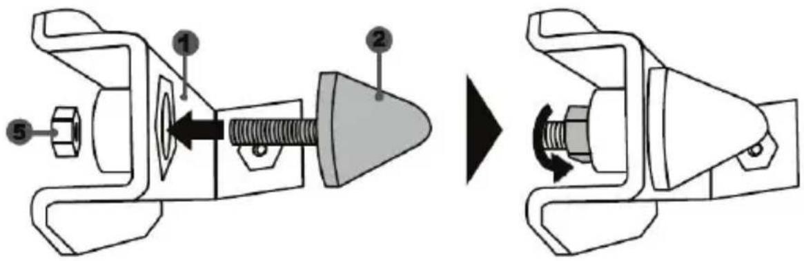
- Position the unit at the back of the brake pedal's arm.
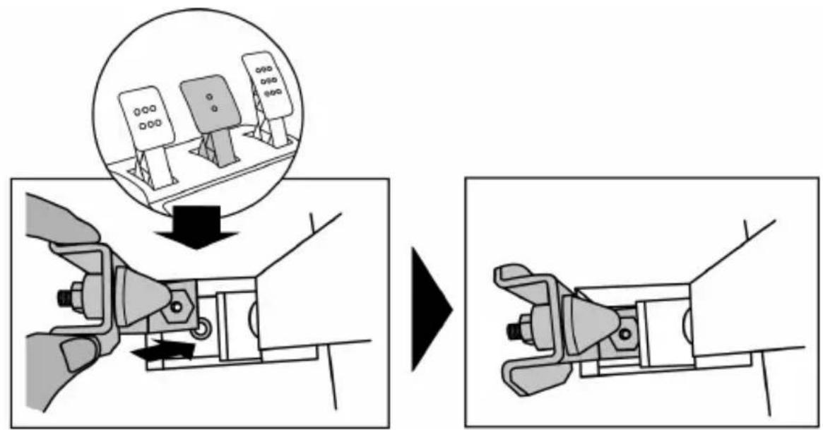
- Using the included 2.5 mm Allen key (4), attach the unit using the attachment screw (3) and the small central screw thread located on the underside of the pedal set.
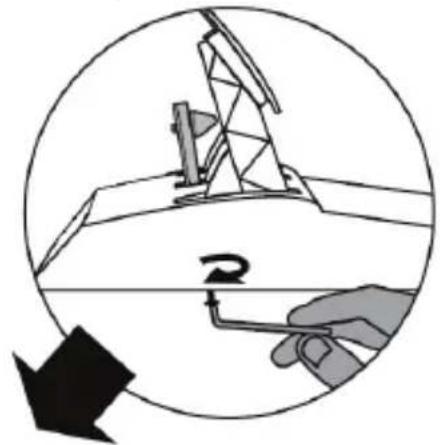
natural_image
Diagram showing a hand holding a tool inside a circular frame with an arrow indicating rotation (no text or symbols)
flowchart
graph TD
    A["○"] --> B["○"]
    C["⊕"] --> D["○"]
    E["●"] --> F["○"]
    G["⊕"] --> H["○"]
    I["●"] --> J["○"]
    K["●"] --> L["○"]
    M["●"] --> N["○"]
    O["●"] --> P["○"]
    Q["●"] --> R["○"]
    S["●"] --> T["○"]
    U["●"] --> V["○"]
    W["●"] --> X["○"]
    Y["●"] --> Z["○"]
The "CONICAL RUBBER BRAKE" mod is now installed!
Adjusting the brake pedal's RANGE of travel and STRENGTH of resistance
By slightly unscrewing the nut (5), you can further strengthen the resistance of the brake pedal by moving the conical stop (2) closer to the back of the pedal's arm (if necessary, use a 14 mm wrench or pliers to re-tighten the nut and maintain the selected position). The closer the conical stop is positioned to the back of the pedal's arm, the greater the strength of resistance will be.
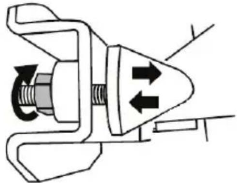
natural_image
Mechanical component diagram showing a valve mechanism with directional arrows (no text or symbols)Note: When the conical stop is very close to the back of the brake pedal's arm, you may experience difficulties in reaching the maximum calibration value. Should that be the case:
* Slowly, press very hard on the brake pedal so as to reach the maximum value (if necessary, stand very briefly on the pedal – just for a second), then release the pressure; or else
* Move the conical stop a bit farther away from the back of the brake pedal's arm.
CONSUMER WARRANTY INFORMATION
Worldwide, Guillemot Corporation S.A., whose registered office is located at Place du Granier, B.P. 97143, 35571 Chantepie, France (hereinafter "Guillemot") warrants to the consumer that this Thrustmaster product shall be free from defects in materials and workmanship, for a warranty period which corresponds to the time limit to bring an action for conformity with respect to this product. In the countries of the European Union, this corresponds to a period of two (2) years from delivery of the Thrustmaster product. In other countries, the warranty period corresponds to the time limit to bring an action for conformity with respect to the Thrustmaster product according to applicable laws of the country in which the consumer was domiciled on the date of purchase of the Thrustmaster product (if no such action exists in the corresponding country, then the warranty period shall be one (1) year from the original date of purchase of the Thrustmaster product).
Notwithstanding the above, rechargeable batteries are covered by a warranty period of six (6) months from the date of original purchase.
Should the product appear to be defective during the warranty period, immediately contact Technical Support, who will indicate the procedure to follow. If the defect is confirmed, the product must be returned to its place of purchase (or any other location indicated by Technical Support).
Within the context of this warranty, the consumer's defective product shall, at Technical Support's option, be either replaced or returned to working order. If, during the warranty period, the Thrustmaster product is subject to such reconditioning, any period of at least seven (7) days during which the product is out of use shall be added to the remaining warranty period (this period runs from the date of the consumer's request for intervention or from the date on which the product in question is made available for reconditioning, if the date on which the product is made available for reconditioning is subsequent to the date of the request for intervention). If permitted under applicable law, the full liability of Guillemot and its subsidiaries (including for consequential damages) is limited to the return to working order or the replacement of the Thrustmaster product. If permitted under applicable law, Guillemot disclaims all warranties of merchantability or fitness for a particular purpose.
This warranty shall not apply: (1) if the product has been modified, opened, altered, or has suffered damage as a result of inappropriate or abusive use, negligence, an accident, normal wear, or any other cause unrelated to a material or manufacturing defect (including, but not limited to, combining the Thrustmaster product with any unsuitable element, including in particular power supplies, rechargeable batteries, chargers, or any other elements not supplied by Guillemot for this product); (2) if the product has been used for any use other than home use, including for professional or commercial purposes (game rooms, training, competitions, for example); (3) in the event of failure to comply with the instructions provided by Technical Support; (4) to software, said software being subject to a specific warranty; (5) to consumables (elements to be replaced over the product's lifespan: disposable batteries, audio headset or headphone ear pads, for example); (6) to accessories (cables, cases, pouches, bags, wrist-straps, for example); (7) if the product was sold at public auction.
This warranty is nontransferable.
The consumer's legal rights with respect to laws applicable to the sale of consumer goods in his or her country are not affected by this warranty.
Additional warranty provisions
During the warranty period, Guillemot shall not provide, in principle, any spare parts, as Technical Support is the only party authorized to open and/or recondition any Thrustmaster product (with the exception of any reconditioning procedures which Technical Support may request that the consumer carry out, by way of written instructions – for example, due to the simplicity and the lack of confidentiality of the reconditioning process – and by providing the consumer with the required spare part(s), where applicable).
Given its innovation cycles and in order to protect its know-how and trade secrets, Guillemot shall not provide, in principle, any reconditioning notification or spare parts for any Thrustmaster product whose warranty period has expired.
In the United States of America and in Canada, this warranty is limited to the product's internal mechanism and external housing. In no event shall Guillemot or its affiliates be held liable to any third party for any consequential or incidental damages resulting from the breach of any express or implied warranties. Some States/Provinces do not allow limitation on how long an implied warranty lasts or exclusion or limitation of liability for consequential or incidental damages, so the above limitations or exclusions may not apply to you. This warranty gives you specific legal rights, and you may also have other rights which vary from State to State or Province to Province.
Liability
If permitted under applicable law, Guillemot Corporation S.A. (hereinafter "Guillemot") and its subsidiaries disclaim all liability for any damages caused by one or more of the following: (1) the product has been modified, opened or altered; (2) failure to comply with assembly instructions; (3) inappropriate or abusive use, negligence, an accident (an impact, for example); (4) normal wear; (5) the use of the product for any use other than home use, including for professional or commercial purposes (game rooms, training, competitions, for example). If permitted under applicable law, Guillemot and its subsidiaries disclaim all liability for any damages unrelated to a material or manufacturing defect with respect to the product (including, but not limited to, any damages caused directly or indirectly by any software, or by combining the Thrustmaster product with any unsuitable element, including in particular power supplies, rechargeable batteries, chargers, or any other elements not supplied by Guillemot for this product).
DECLARATION OF CONFORMITY
CANADIAN COMPLIANCE NOTICE: this Class B digital apparatus meets all requirements of the Canadian Interference-Causing Equipment Regulations.
USA COMPLIANCE NOTICE: this equipment has been tested and found to comply with the limits for a Class B digital device, pursuant to Part 15 of the FCC rules. Operation is subject to the following two conditions:
(1) This device may not cause harmful interference, and
(2) This device must accept any interference received, including interference that may cause undesired operation.
These limits are designed to provide reasonable protection against harmful interference in a residential installation. This equipment generates, uses and can radiate radio frequency energy and, if not installed and used in accordance with the instructions, may cause harmful interference to radio communications. However, there is no guarantee that interference will not occur in a particular installation. If this equipment does cause harmful interference to radio or television reception, which can be determined by turning the equipment on and off, the user is encouraged to try to correct the interference by one or more of the following measures:
- Reorient or relocate the receiving antenna.
- Increase the separation between the equipment and receiver.
- Connect the equipment into an outlet on a circuit different from that to which the receiver is connected.
- Consult the dealer or an experienced radio/TV technician for help.
THRUSTMASTER®
TECHNICAL SUPPORT
http://support.thrustmaster.com

natural_image
Three black icons: a lowercase 'i' in a circle, an envelope symbol, and a telephone handset (no text or labels)COPYRIGHT
© 2017 Guillemot Corporation S.A. All rights reserved. Thrustmaster® is a registered trademark of Guillemot Corporation S.A.
Manufactured & distributed under license from Sony Interactive Entertainment America LLC.
Playstation, the PS family logo, PS3, PS4 and “△OX□” are registered trademarks of Sony Interactive Entertainment Inc. All rights reserved.
Gran Turismo and Gran Turismo logo are registered trademarks or trademarks of Sony Interactive Entertainment Inc.
All other trademarks and brand names are hereby acknowledged and are property of their respective owners. Illustrations not binding. Contents, designs and specifications are subject to change without notice and may vary from one country to another. Made in China.
TouchSense® Technology licensed from Immersion Software Ireland Limited. Protected by one or more of the U.S. Patents found at the following address www.immersion.com/patent-marking.html and other patents pending.
ENVIRONMENTAL PROTECTION RECOMMENDATION
Please adhere to local recycling laws for electrical and electronic equipment.
Retain this information. Colors and decorations may vary.
Plastic fasteners and adhesives should be removed from the product before it is used.
www.thrustmaster.com


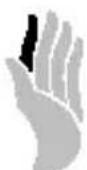
immersion.

T-GT
natural_image
Technical line drawing of a steering wheel and motor control panel (no text or symbols)ATTENTION :
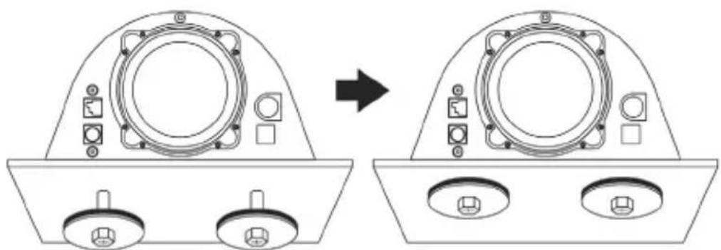
natural_image
Diagram showing a device component before and after transformation, with no visible text or symbols.natural_image
Technical line drawing of a mechanical component with no visible text or symbols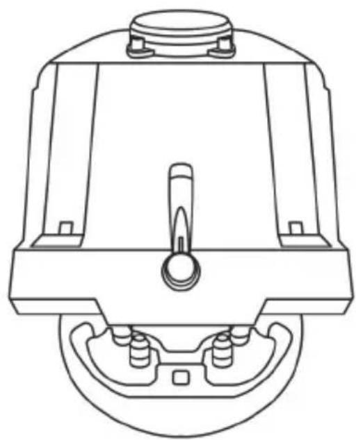
natural_image
Technical line drawing of a mechanical component with no visible text or symbolsATTENTION !:
natural_image
Line drawing of a device with three speakers on top (no text or symbols)CARACTÉRISTIQUES TECHNIQUES
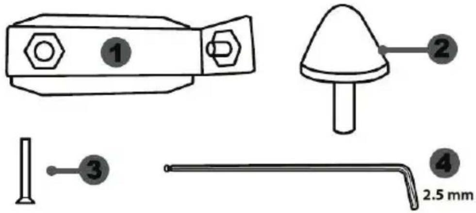
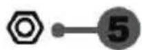
natural_image
Diagram showing two mechanical components with a downward arrow indicating motion or change (no text or symbols)Position basse

natural_image
Diagram showing two identical mechanical components with a central arrow indicating upward motion (no text or symbols)Position haute
natural_image
Diagram of a mechanical device with two views showing internal components and directional arrows (no text or symbols)Position à gauche
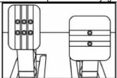
natural_image
Technical line drawing of two mechanical components with mounting holes, no text or symbols presentnatural_image
Diagram showing two mechanical components with arrows indicating direction of movement (no text or symbols)Position à droite
natural_image
Diagram of a mechanical structure with triangular supports and a directional arrow (no text or symbols)natural_image
Diagram of a mechanical structure with an arrow indicating direction, no text or symbols presentnatural_image
Illustration of an oil pumpjack inside a circular frame with a hand holding a tool, no text or symbols present.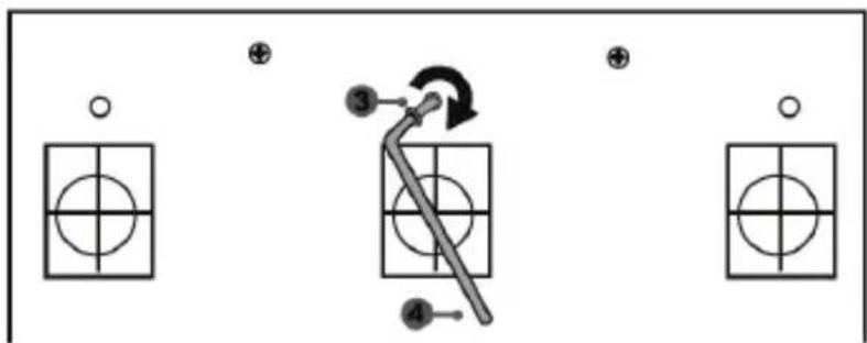
flowchart
graph TD
    A["Input"] --> B["Step 1: Circle with cross"]
    B --> C["Step 2: Arrow with arrow indicating rotation"]
    C --> D["Step 3: Arrow with circle inside grid"]
    D --> E["Step 4: Arrow with circle inside grid"]
    E --> F["Output"]
natural_image
Mechanical assembly diagram showing a valve mechanism with directional arrows (no text or labels)INFORMATIONS RELATIVES A LA GARANTIE AUX CONSOMMATEURS
www.thrustmaster.com


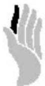
immersion.

T-GT
Manual del usuario
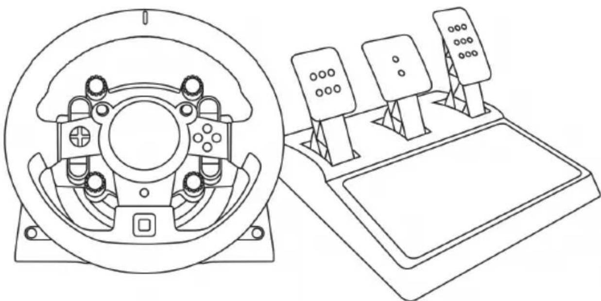
natural_image
Technical line drawing of a steering wheel and control panel assembly (no text or symbols)ADVERTENCIA:
natural_image
Diagram of a mechanical assembly with rotating components and directional arrows (no text or symbols)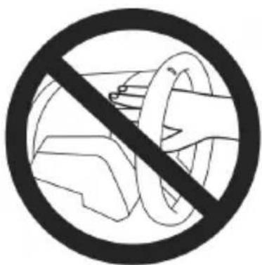


natural_image
Diagram showing a device component before and after transformation, with no visible text or symbols.natural_image
Technical line drawing of a mechanical assembly with no visible text or symbols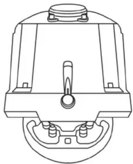
natural_image
Technical line drawing of a mechanical component with no visible text or symbolsATENCIÓN:
natural_image
Line drawing of a device with three speakers on top (no text or symbols)CARACTERÍSTICAS TÉCNICAS


natural_image
Diagram showing two mechanical components with a downward arrow indicating motion or change (no text or symbols present)Posición baja

natural_image
Diagram showing two identical mechanical components with a directional arrow, no text or symbols presentPosición alta
natural_image
Technical diagram showing two mechanical components with arrows indicating direction (no text or symbols)Posición izquierda
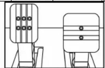
natural_image
Two identical mechanical components with circular holes, shown in line drawing style (no text or symbols)natural_image
Diagram showing two mechanical components with arrows indicating direction of movement (no text or symbols)Posición derecha
natural_image
Diagram of a mechanical structure with triangular supports and a directional arrow (no text or symbols)natural_image
Diagram of a mechanical structure with an arrow indicating direction, no text or symbols presentnatural_image
Illustration of an oil pumpjack inside a circular frame, with a hand holding a tool and a black arrow indicating rotation (no text or symbols)
flowchart
graph TD
    A["Step ③"] --> B["Arrow to Step ④"]
    B --> C["Step ④"]
    D["Step ④"] --> E["Step ③"]
    F["Step ③"] --> G["Step ④"]
    H["Step ④"] --> I["Step ③"]
natural_image
Mechanical component diagram showing a valve mechanism with directional arrows (no text or symbols)www.thrustmaster.com


immersion.

T-GT
PARA SISTEMAS PLAYSTATION®3 – PLAYSTATION®4
Manual do Usuário

natural_image
Technical line drawing of a steering wheel and three control switches (no text or symbols)ATENÇÃO:
natural_image
Diagram of a mechanical device with rotating arms and control buttons, enclosed in a circular frame (no text or symbols)NUNCA

NUNCA
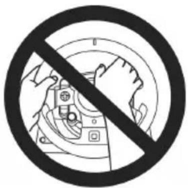


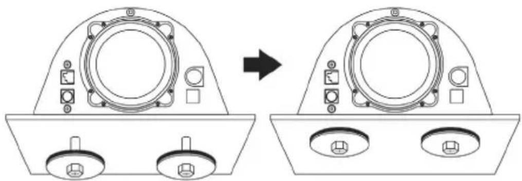
natural_image
Technical line drawing showing a device component before and after assembly, with no visible text or symbols.natural_image
Technical line drawing of a mechanical device with internal components and mounting points (no text or symbols)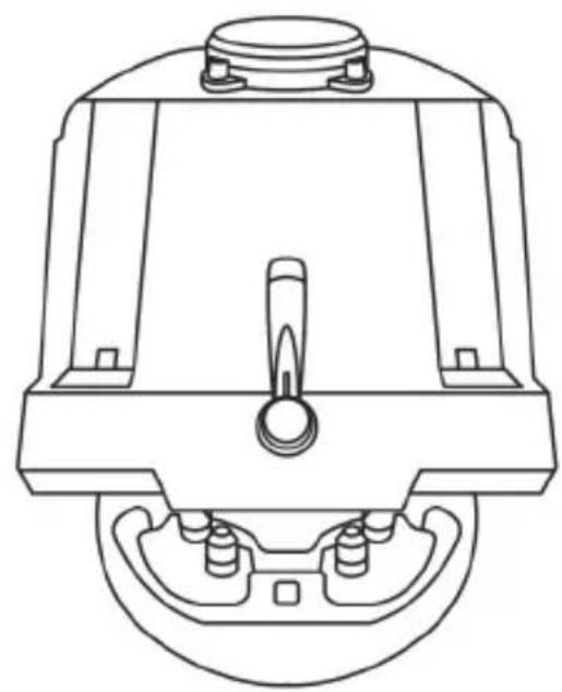
natural_image
Technical line drawing of a mechanical component with no visible text or symbolsATENÇÃO:
natural_image
Line drawing of a device with three speakers on top (no text or symbols)CARACTERÍSTICAS TÉCNICAS
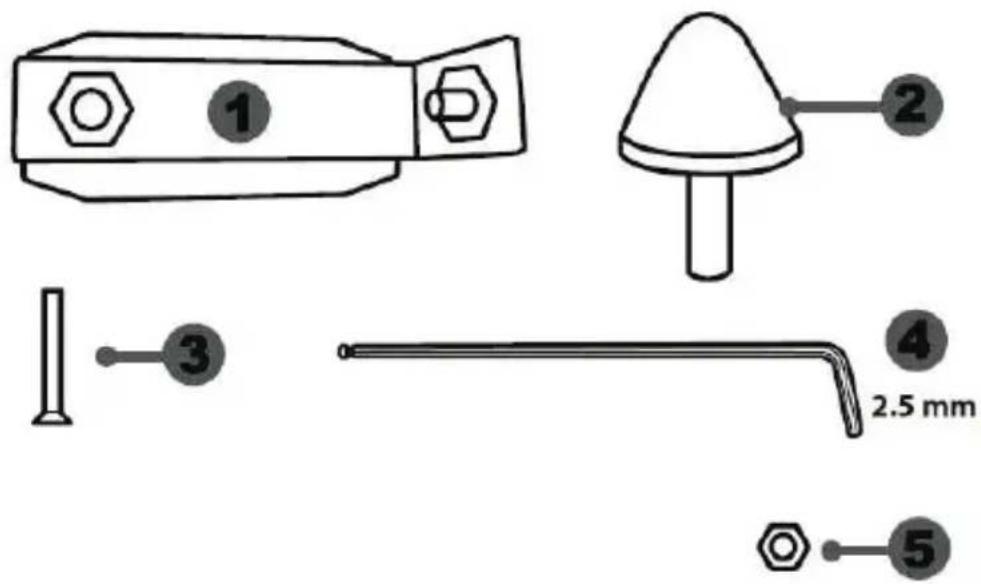
FIXAR O CONJUNTO DE PEDAIS A UM COCKPIT
- Fixe o conjunto de pedais utilizando as pequenas roscas de parafusos situadas na parte inferior do conjunto de pedais.
- Enrosque dois parafusos M6 (não incluídos) na chapa de apoio do conjunto de pedais e nas duas pequenas roscas de parafusos situadas na parte inferior do conjunto de pedais.
natural_image
Diagram showing two mechanical components with a downward arrow indicating motion or change (no text or symbols)Posição baixa

natural_image
Diagram showing two identical mechanical components with a directional arrow, no text or symbols presentPosição alta
natural_image
Technical diagram showing two mechanical components with arrows indicating direction (no text or symbols)Posição à esquerda
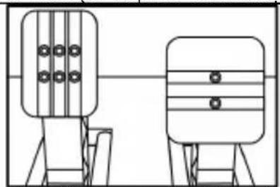
natural_image
Two identical mechanical or electronic components with vertical bars and circular holes, shown side by side (no text or symbols)natural_image
Diagram showing two mechanical components with arrows indicating motion or assembly (no text or symbols)Posição à direita
natural_image
Diagram of a mechanical structure with a triangular frame and an arrow indicating upward motion (no text or symbols)natural_image
Diagram of a mechanical structure with an arrow indicating direction, no text or symbols presentnatural_image
Diagram showing a hand operating a drilling rig with a circular arrow indicating rotation (no text or symbols)
flowchart
graph TD
    A["○"] --> B["○"]
    C["⊕"] --> D["○"]
    E["●"] --> F["○"]
    G["⊕"] --> H["○"]
    I["●"] --> J["○"]
    K["●"] --> L["○"]
    M["●"] --> N["○"]
    O["●"] --> P["○"]
natural_image
Mechanical component diagram showing a valve mechanism with directional arrows (no text or labels)www.thrustmaster.com


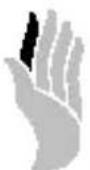
immersion.

T-GT
ユーザーズマニュアル
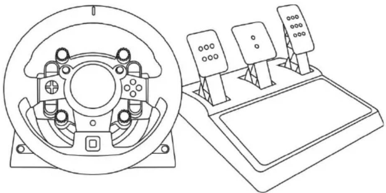
natural_image
Technical line drawing of a steering wheel and control panel assembly (no text or symbols)警告:
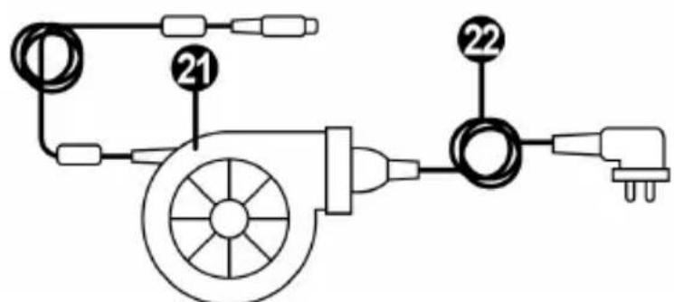
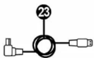
natural_image
Technical diagram of a mechanical assembly with circular components and directional arrows (no text or labels)
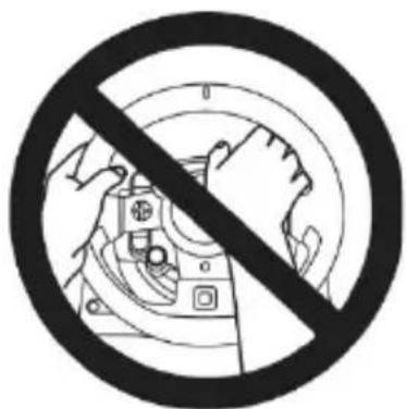

natural_image
Prohibition sign showing a crossed-out mechanical component (no text or symbols)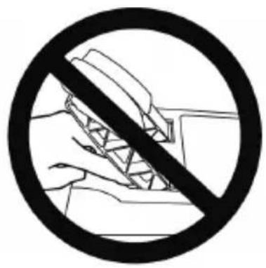
natural_image
Prohibition sign with diagonal line crossing over hands, no text or symbols present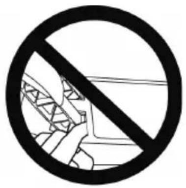

flowchart
graph TD
    A["Component 1: Top-left, Top-right"] --> B["Component 2: Top-center, Top-right"]
    B --> C["Component 3: Top-center, Top-right"]
    C --> D["Component 4: Top-center, Top-right"]
    D --> E["Final Assembly: Tool with Component 1"]

natural_image
Technical line drawing showing a device component before and after assembly, with no visible text or symbols.natural_image
Technical line drawing of a mechanical device with internal components and mounting feet (no text or symbols)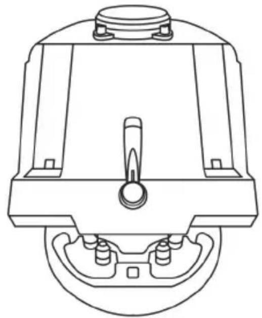
natural_image
Technical line drawing of a mechanical component with no visible text or symbols警告:
natural_image
Line drawing of a device with three speakers on top (no text or symbols)付属品
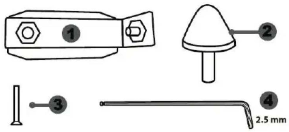
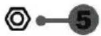
natural_image
Prohibition sign with diagonal line crossing over a mechanical component (no text or symbols)危険

危険
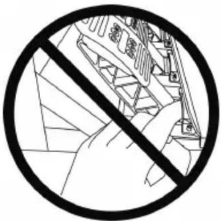
natural_image
Black and white prohibition symbol over a stylized building facade, no text or symbols presentペダルの自動調整

重要:
natural_image
Two identical diagrams showing a shield-like object being lowered from its side, with arrows indicating the process (no text or symbols present)低ポジション 高ポジション
natural_image
Technical diagram showing two mechanical components with arrows indicating direction (no text or symbols)左ポジショ
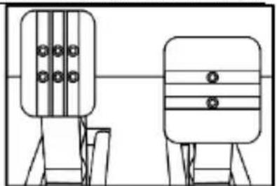
natural_image
Two identical mechanical or electrical components with vertical bars and circular holes, shown side by side (no text or symbols)中央ポジション(デフォルト)
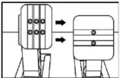
natural_image
Diagram showing two mechanical components with arrows indicating motion or assembly (no text or symbols)右ポジション
natural_image
Diagram of a ladder structure with an arrow indicating upward motion (no text or symbols present)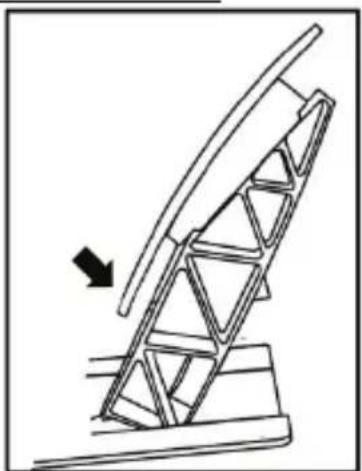
natural_image
Diagram of a mechanical structure with an arrow indicating direction, no text or symbols present傾き小 傾き大(デフォルト)
natural_image
Diagram showing a hand holding a tool inside a circular frame with an oil pumpjack, and a black arrow indicating rotation (no text or symbols)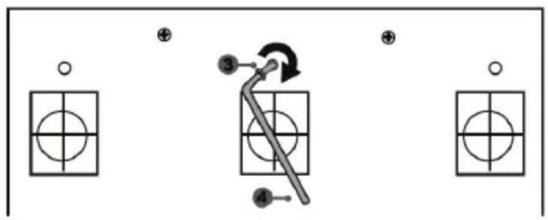
natural_image
Mechanical component diagram showing a valve mechanism with directional arrows (no text or symbols)All rights reserved.
Gran Turismo, “グランツーリスモ” and Gran Turismo logo are registered trademarks or trademarks of Sony Interactive Entertainment Inc.
www.thrustmaster.com
Made in China.

:外箱
CE
FC

immersion.
T-GT
用户手册
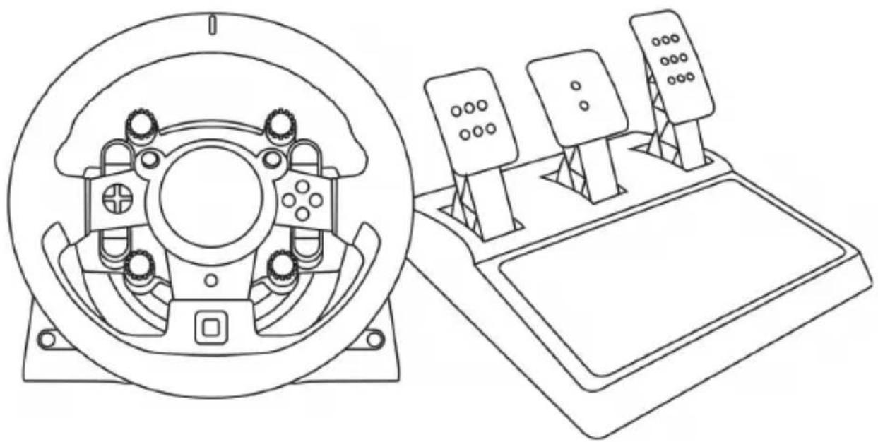
natural_image
Technical line drawing of a steering wheel and control console (no text or symbols)警告:
natural_image
Diagram of a mechanical assembly with rotating components and directional arrows (no text or labels)绝对禁止

绝对禁止


警告 — 玩游戏时踏板组夹住危险
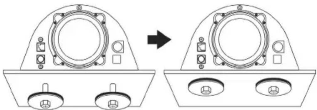
natural_image
Technical line drawing showing a device component before and after assembly, with no visible text or symbols.natural_image
Line drawing of a three-pin electronic device with three speakers and a base (no text or symbols)技术特性
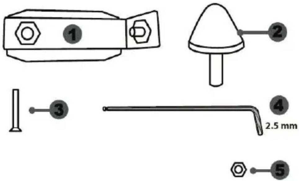
6 金属踏板臂
7 塑料踏板头支架
8 金属踏板头
警告
natural_image
Prohibition sign showing a hand using a tool to cut a mechanical component (no text or symbols)绝对禁止

natural_image
Black and white pictogram showing a ship being blocked by a diagonal line through a circular border (no text or symbols)绝对禁止

natural_image
Prohibition sign showing a hand holding a bicycle under construction, enclosed in a circle (no text or symbols)踏板自动校准

重要说明:
natural_image
Diagram showing two mechanical components with a downward arrow indicating motion or change (no text or symbols present)低位
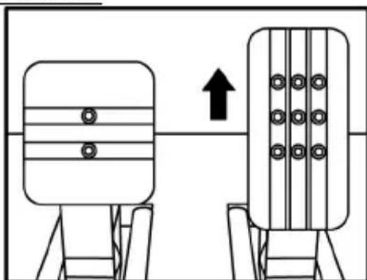
natural_image
Two identical mechanical components with circular holes, one upward and one with grid-like elements, connected by a line (no text or symbols)高位
调节油门踏板和离合器踏板的间距
natural_image
Diagram showing two mechanical components with arrows indicating direction of movement (no text or symbols)左侧位置
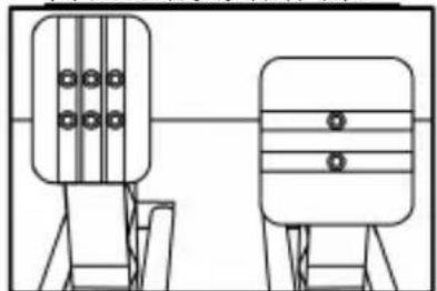
natural_image
Two identical mechanical or electrical components with vertical connectors and horizontal bands, no text or symbols visible.居中位置(默认)
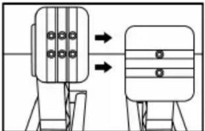
natural_image
Diagram showing two mechanical components with arrows indicating direction of movement (no text or symbols)右侧位置
每个踏板的可能间距位置数目:
- 加速踏板三个
- 离合器踏板三个
调节三个踏板的倾角
natural_image
Diagram of a ladder structure with an arrow indicating upward motion (no text or symbols)小倾角位置
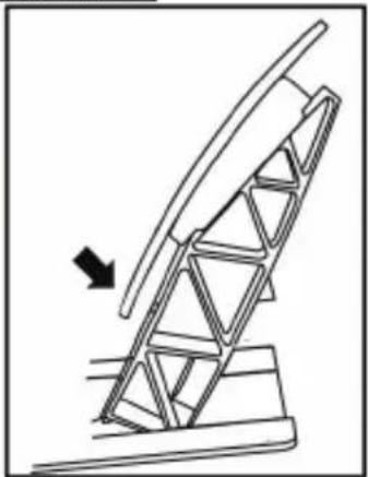
natural_image
Diagram of a mechanical structure with an arrow indicating direction, no text or symbols present大倾角位置(默认)
每个踏板的可能倾角位置数目:
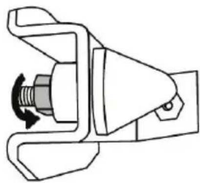
natural_image
Mechanical component diagram showing a rotating shaft and housing assembly (no text or symbols)- 将该部件装在单元刹车踏板臂的背面。
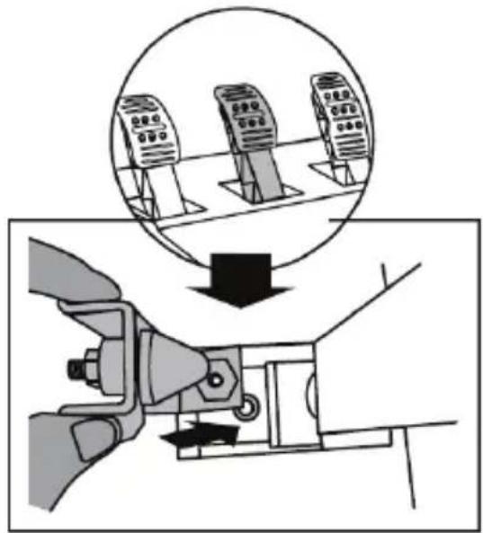
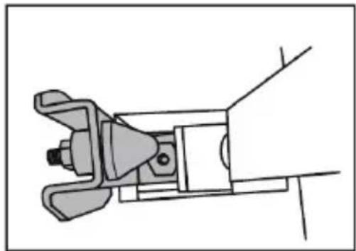
natural_image
Technical line drawing of a mechanical clamp or bracket assembly (no text or symbols)natural_image
Illustration of an oil pumpjack inside a circular frame, with a hand holding a tool and a black arrow indicating rotation (no text or symbols)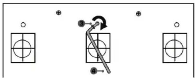
flowchart
graph TD
    A["Component 1"] --> B["Component 2"]
    C["Component 3"] --> D["Component 4"]
    E["Component 5"] --> F["Component 6"]
    G["Component 7"] --> H["Component 8"]
    I["Component 9"] --> J["Component 10"]
    K["Component 11"] --> L["Component 12"]
    M["Component 13"] --> N["Component 14"]
    O["Component 15"] --> P["Component 16"]
    Q["Component 17"] --> R["Component 18"]
    S["Component 19"] --> T["Component 20"]
    U["Component 21"] --> V["Component 22"]
    W["Component 23"] --> X["Component 24"]
    Y["Component 25"] --> Z["Component 26"]
    AA["Component 27"] --> AB["Component 28"]
    AC["Component 29"] --> AD["Component 30"]
natural_image
Mechanical component diagram showing a valve mechanism with directional arrows (no text or labels)natural_image
Technical line drawing of a mechanical device with circular housing and control panel (no text or symbols)警告:
natural_image
Diagram of a mechanical assembly with rotating components and directional arrows (no text or symbols)禁止

禁止


注意-遊玩時請小心別被腳踏板組夾傷
natural_image
Prohibition sign with crossed-out hand holding a tool, no text or symbols present禁止

natural_image
Prohibition sign showing hands using a device to avoid collision (no text or symbols)禁止
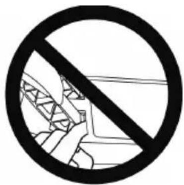

注意-非遊玩時亦請小心別被腳踏板夾傷
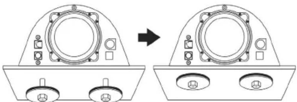
natural_image
Technical line drawing showing a device component before and after assembly, with no visible text or symbols.natural_image
Technical line drawing of a mechanical assembly with no visible text or symbols禁止
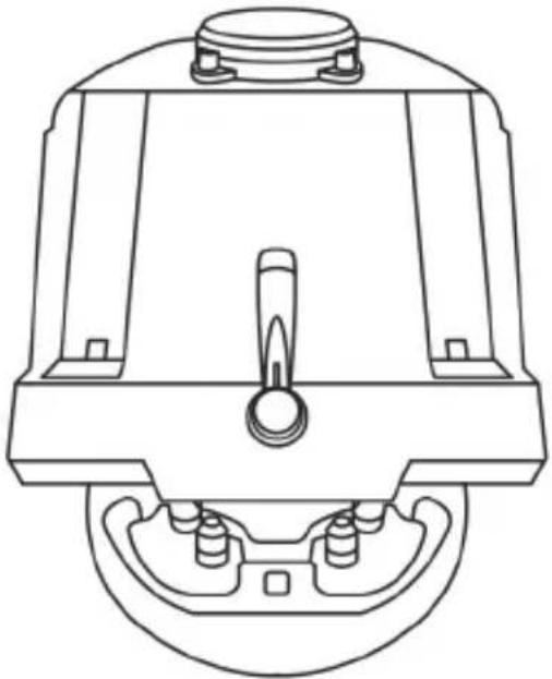
natural_image
Technical line drawing of a mechanical component with no visible text or symbols警告:
natural_image
Line drawing of a mechanical device with three vertical supports and three circular components on top (no text or symbols)技術特點
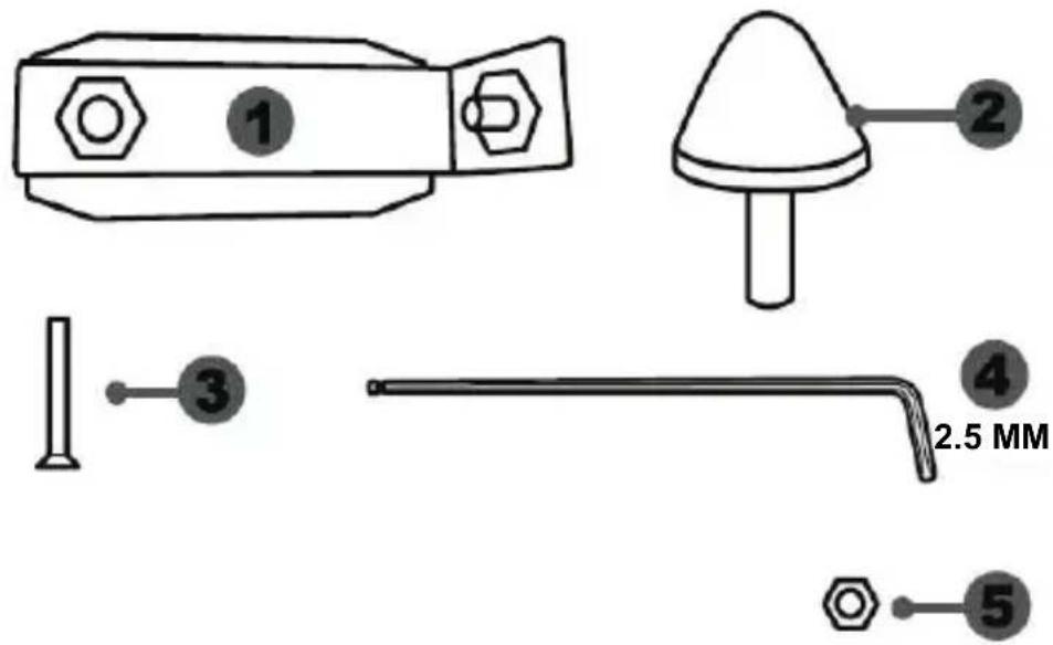
1 錐形塞金屬支架(並未預設安裝)
4 2.5 mm 內六角扳手(隨附)
2 錐形塞
5 錐形塞位置調整螺母
3 金屬支架固定螺桿
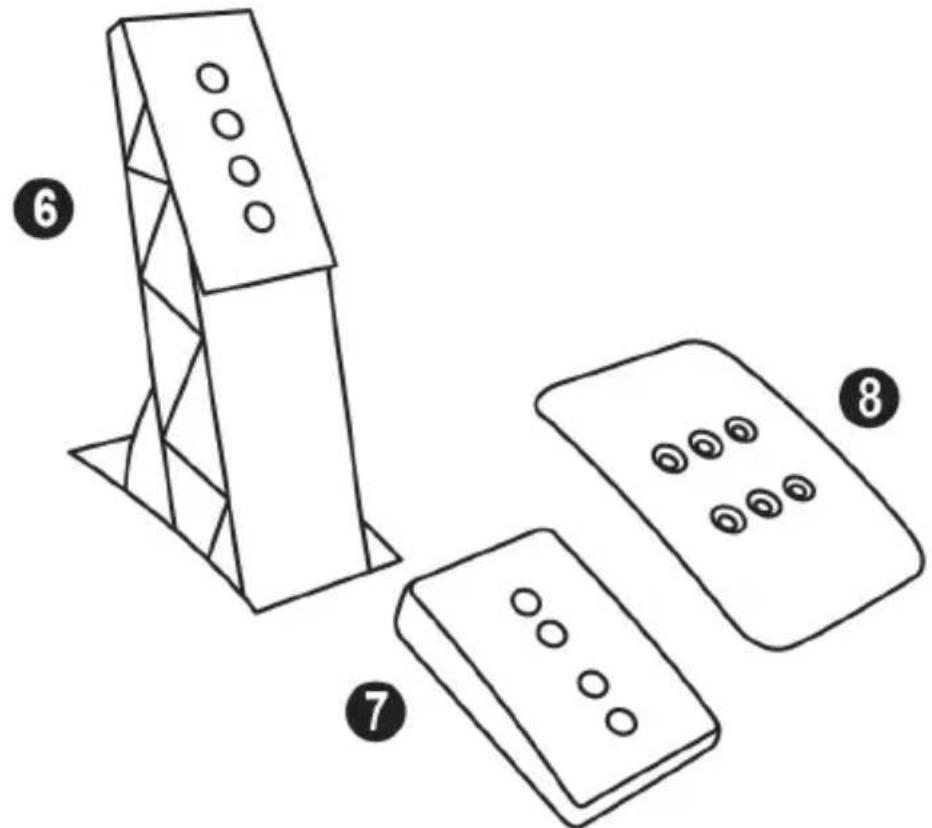
6 金屬踏板臂
8 金屬踏板頭
7 腳踏板頭支架
警告
natural_image
Prohibition sign showing a hand holding a mechanical device against a circle (no text or symbols)禁止
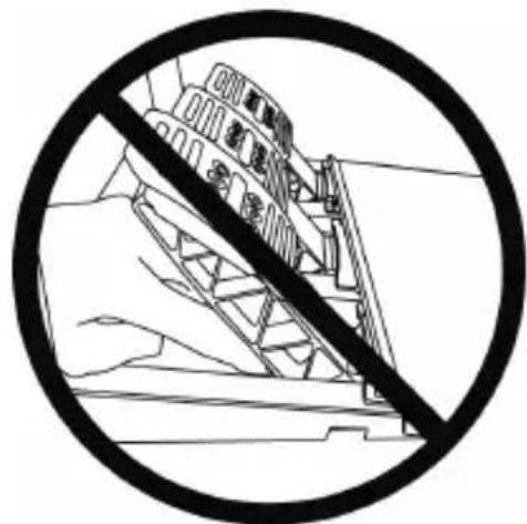
natural_image
Black and white prohibition symbol on a mountain slope, no text or symbols present禁止
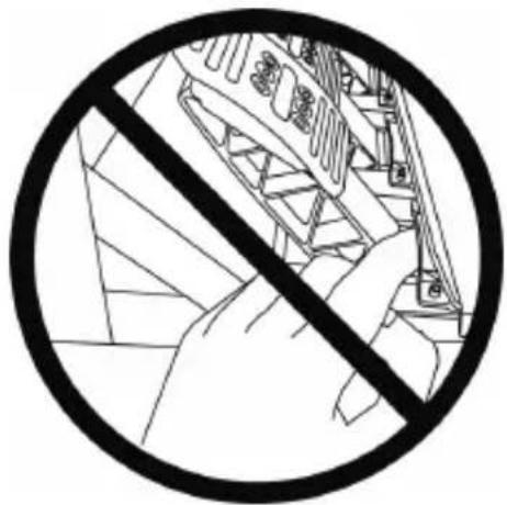
natural_image
Black and white prohibition symbol over a mechanical device, no text or symbols present自動校準腳踏板組

重要提示:
natural_image
Two-panel diagram showing a mechanical or architectural component before and after assembly, with arrows indicating direction (no text or symbols)低位置(預設) 高位置
調節油門踏板和離合器踏板的間距
natural_image
Diagram showing two mechanical components with arrows indicating direction, no text or symbols present靠左位置
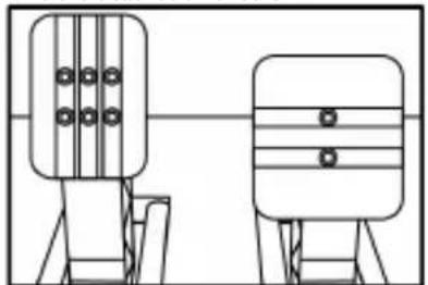
natural_image
Two identical mechanical components with circular holes, shown side by side without any text or symbols.置中位置(預設)

natural_image
Diagram showing two mechanical components with arrows indicating motion or assembly (no text or symbols)靠右位置
每個踏板可能的間隔位置數:
- 油門踏板:3個
- 離合器踏板:3 個
調節三個踏板的傾角
natural_image
Diagram of a mechanical structure with a triangular frame and an upward arrow, no text or symbols present較平位置
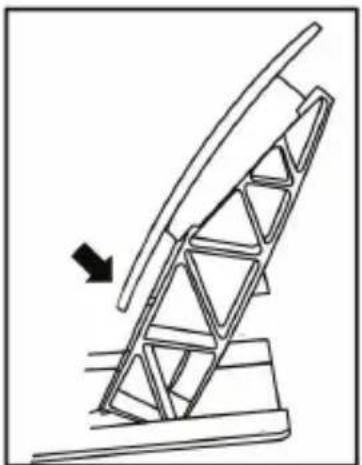
natural_image
Diagram of a mechanical structure with an arrow indicating direction, no text or symbols present較斜位置(預設)
每個踏板可能的傾斜位置數:
- 油門踏板:2 個
- 煞車踏板:2個
- 離合器踏板:2 個
安裝錐形塞(「錐形橡膠煞車器」修改器)
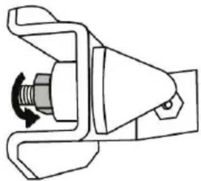
natural_image
Mechanical component diagram showing a valve mechanism with a rotating knob (no text or symbols)- 將修改器置於煞車踏板臂背部。
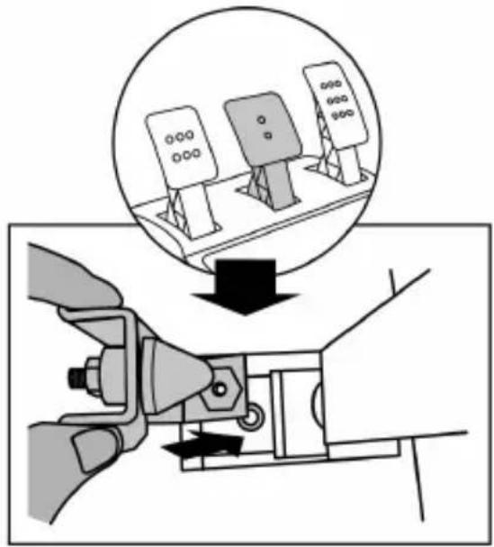
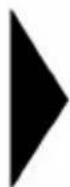
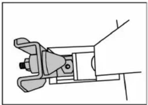
natural_image
Technical line drawing of a mechanical clamp or bracket assembly (no text or symbols)natural_image
Illustration of an oil pumpjack inside a circle with a hand holding a tool, no text or symbols present.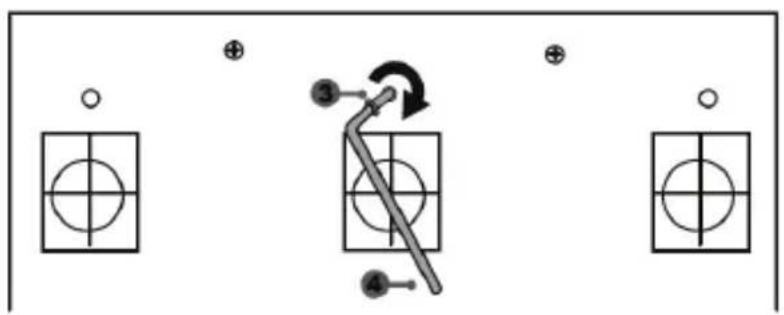
「錐形橡膠煞車器」修改器已安裝成功!
調整煞車踏板的行動範圍及阻力強度
natural_image
Mechanical component diagram showing a rotating shaft and housing with directional arrows (no text or symbols)natural_image
Technical line drawing of a mechanical device with a circular component and a multi-plate control panel (no text or symbols)경고:
natural_image
Diagram of a mechanical assembly with rotating components and directional arrows (no text or symbols)절대 금지

절대 금지


natural_image
Prohibition sign with diagonal line crossing over a construction site (no text or symbols)절대 금지
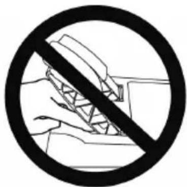
natural_image
Prohibition sign with diagonal line crossing over hands holding a construction site (no text or symbols)절대 금지
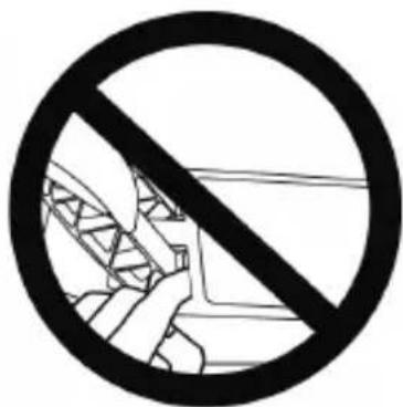

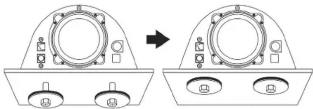
natural_image
Technical line drawing showing a device component before and after transformation, with no visible text or symbols.natural_image
Line drawing of a device with three speakers on top (no text or symbols)기술적 특징
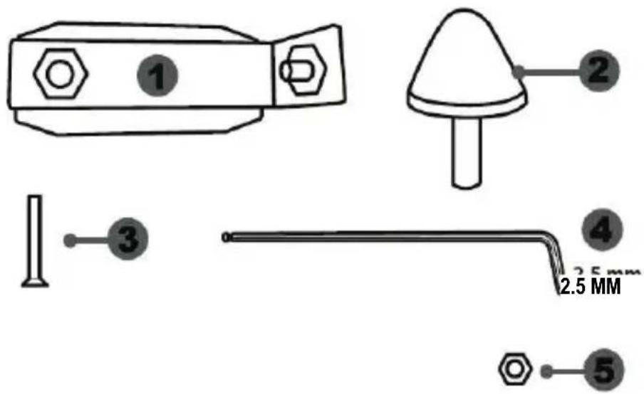
절대 금지
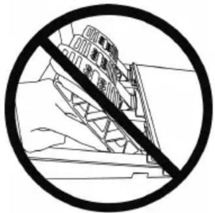
절대 금지
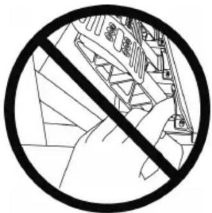
natural_image
Prohibition sign with diagonal line crossing over a mechanical component diagram (no text or symbols)페달 자동 보정

중요:
natural_image
Diagram showing two mechanical components with a downward arrow indicating motion or change (no text or symbols present)낮은 위치(기본 위치)
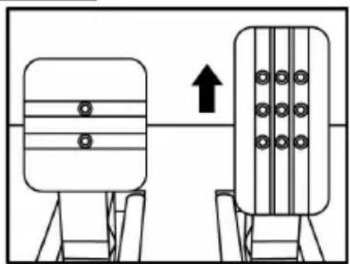
natural_image
Diagram showing two mechanical components with a directional arrow, no text or symbols present높은 위치
natural_image
Diagram showing two mechanical components with arrows indicating direction, no text or symbols present왼쪽 위치

natural_image
Two identical mechanical components with vertical bars and circular holes, mounted on support stands (no text or symbols)가운데 위치(기본 위치)
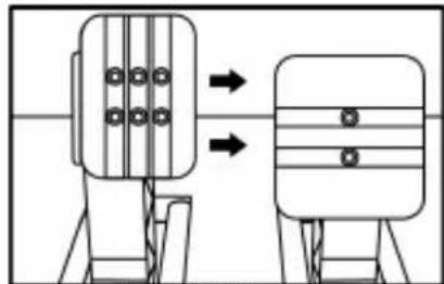
natural_image
Diagram showing two mechanical components with arrows indicating direction of movement (no text or symbols)오른쪽 위치
페달 별 가능한 간격 위치 수:
-가속페달3개
-클러치 페달 3 개
3 개의 폐달 '경사' 조정
natural_image
Diagram of a ladder structure with an arrow indicating upward motion (no text or symbols)덜 경사진 위치
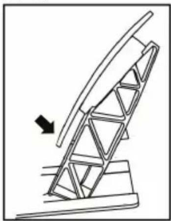
natural_image
Diagram of a mechanical ladder system with an arrow indicating motion direction (no text or symbols)더 경사진 위치(기본 위치)
페달 별 가능한 경사 위치 수:
- 가속 폐달용 2 개
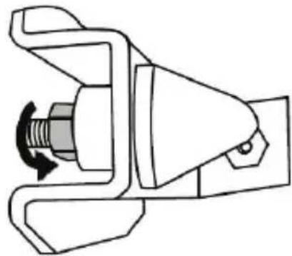
natural_image
Technical line drawing of a mechanical clamp or lever assembly (no text or symbols)
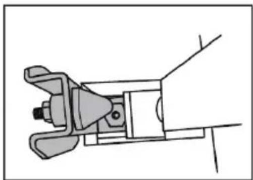
natural_image
Technical line drawing of a mechanical clamp or bracket assembly (no text or symbols)natural_image
Illustration of an oil pumpjack inside a circular frame, with a hand holding a tool near the base (no text or symbols)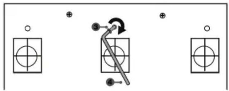
flowchart
graph TD
    A["Component 1"] --> B["Component 2"]
    B --> C["Component 3"]
    C --> D["Component 4"]
    style A fill:#f9f,stroke:#333
    style B fill:#ccf,stroke:#333
    style C fill:#cfc,stroke:#333
    style D fill:#fcc,stroke:#333
natural_image
Mechanical component diagram showing a valve mechanism with directional arrows (no text or labels)natural_image
Technical line drawing of a steering wheel and control panel assembly (no text or symbols)WARNING:
To ensure that your T-GT racing wheel functions correctly with games, you may be required to install the game's automatic updates (available when your system is connected to the Internet).
TECHNICAL FEATURES

1 T-GT base
2 T-GT wheel
3 2 sequential paddle shifters (up & down)
4 Directional buttons
5 4 rotary selectors with Push function (compatible with the PS4 ^TM system in GT mode and on PC)
6 2 mini-sticks (compatible with the PS4™ system in GT mode and on PC)
7 SHARE button
8 OPTIONS button
9 PS button
10 MODE button + red/green indicator light
11 Built-in USB sliding switch: OTHER / GT
12 Large threaded hole (for attachment system and fastening screw)
13 Attachment system
14 Metal fastening screw

15 Thrustmaster Quick Release
16 T-DFB effects system (only compatible with the PS4 ^TM system in GT mode)
17 Connector for T-TURBO power supply
18 Connector for removable USB cable
19 Connector for pedal set
20 Connector for TH8A shifter (shifter sold separately)
21 T-TURBO power supply
22 Power supply cable
23 Removable USB cable
PLUGGING THE WHEEL INTO AN ELECTRICAL OUTLET: PLEASE READ CAREFULLY!

Never plug the T-TURBO power supply into an electrical outlet with a different voltage! The
T-TURBO power supply's voltage is indicated on the label located above the female connector for the power supply cable.

Never connect a power supply other than the T-TURBO power supply to the T-GT base,
even if the connector is compatible! For example, never connect the power adapter for the T500 RS wheel to the T-GT base.
WARNING
Before using this product, please read this manual carefully and save it for later reference.

Warning – Electrical shock
* Keep the product in a dry location and do not expose it to dust or sunlight.
* Do not twist or pull on the connectors and cables.
* Do not spill any liquid on the product or its connectors.
* Do not short-circuit the product.
* Never dismantle the product; do not throw it onto a fire and do not expose it to high temperatures.
* Do not use a power supply cable other than the one provided with your racing wheel.
* Do not use the power supply cable if the cable or its connectors are damaged, split or broken.
* Make sure that the power supply cable is properly plugged into an electrical outlet, and properly connected to the connector at the rear of the racing wheel's base.
* Do not open up the racing wheel: there are no user-serviceable parts inside. Any repairs must be carried out by the manufacturer, its authorized representative or a qualified technician.
* Only use attachment systems/accessories specified by the manufacturer.
* If the racing wheel is operating abnormally (if it is emitting any abnormal sounds, heat or odors), stop using it immediately, unplug the power supply cable from the electrical outlet and disconnect the other cables.
* If you will not be using the racing wheel for an extended period of time, unplug its power supply cable from the electrical outlet.
* The electrical outlet must be located near the equipment and must be easily accessible.

Air vents
Make sure not to block any of the air vents on the racing wheel's base. For optimal ventilation, make sure to do the following:
* Position the wheel's base at least 10c m away from any wall surfaces.
* Do not place the base in any tight spaces.
* Do not cover the base.
* Do not let any dust build up on the air vents.

For safety reasons, never use the pedal set with bare feet or while wearing only socks on your feet.
THRUSTMASTER® DISCLAIMS ALL RESPONSIBILITY IN THE EVENT OF INJURY RESULTING FROM USE OF THE PEDAL SET WITHOUT SHOES.

Warning – Injuries due to Force Feedback and repeated movements
Playing with a Force Feedback racing wheel may cause muscle or joint pain. To avoid any problems:
* Avoid lengthy gaming periods.
* Take 10 to 15 minute breaks after each hour of play.
* If you feel any fatigue or pain in your hands, wrists, arms, feet or legs, stop playing and rest for a few hours before you start playing again.

Warning – Injuries due to Force Feedback and repeated movements (continued)
* If the symptoms or pain indicated persist when you start playing again, stop playing and consult your doctor.
* Keep out of children's reach.
* During gameplay, always leave both hands correctly positioned on the wheel without completely letting go.
* During gameplay, never place your hands or your fingers under the pedals or anywhere near the pedal set.
* During calibration and gameplay, never place your hand or your arm through the openings in the racing wheel.
* Make sure that the racing wheel's base is properly secured, as per this manual's instructions.

Product to be handled only by users 16 years of age or older
HEAVY PRODUCT

Be careful not to drop the product on yourself or on anyone else!
ALWAYS
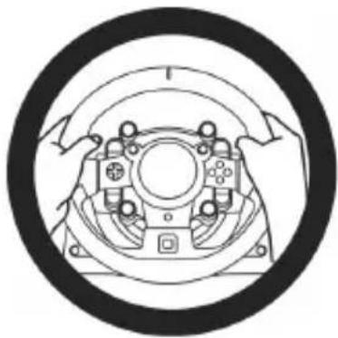
natural_image
Diagram of a mechanical assembly with rotating components and directional arrows (no text or labels)NEVER

NEVER


Warning – Pedal set pinch hazard when playing
* Keep the pedal set out of children's reach.
* During gameplay, never place your fingers on or anywhere near the sides of the pedals.
* During gameplay, never place your fingers on or anywhere near the pedal's rear base.
* During gameplay, never place your fingers on or anywhere near the pedal's front base.


Warning – Pedal set pinch hazard when not playing
* Store the pedal set in a safe place, and keep it out of children's reach.
UPDATING YOUR RACING WHEEL'S FIRMWARE
The firmware included in your racing wheel's base can be updated to a more recent version featuring product enhancements.
To display the firmware version that your racing wheel is currently using and update it if required: on PC, visit http://support.thrustmaster.com. Click Racing Wheels / T-GT, then select Firmware and follow the instructions describing the download and installation procedure.
Important note:
On PC, the USB sliding switch (11) on the racing wheel's base must always be set to the "OTHER" position.
INSTALLING THE WHEEL ON ITS BASE
Align the connector positions using the arrows:
Base (1) connector: Arrow pointing upwards
Racing wheel (2) connector: Arrow pointing upwards
Once the connectors are correctly positioned, simply rotate the Thrustmaster Quick Release (15) device's ring counterclockwise, while holding the racing wheel (2) in position.
Then, tighten the ring as much as you can: to do so, hold the ring in position and rotate the racing wheel clockwise.
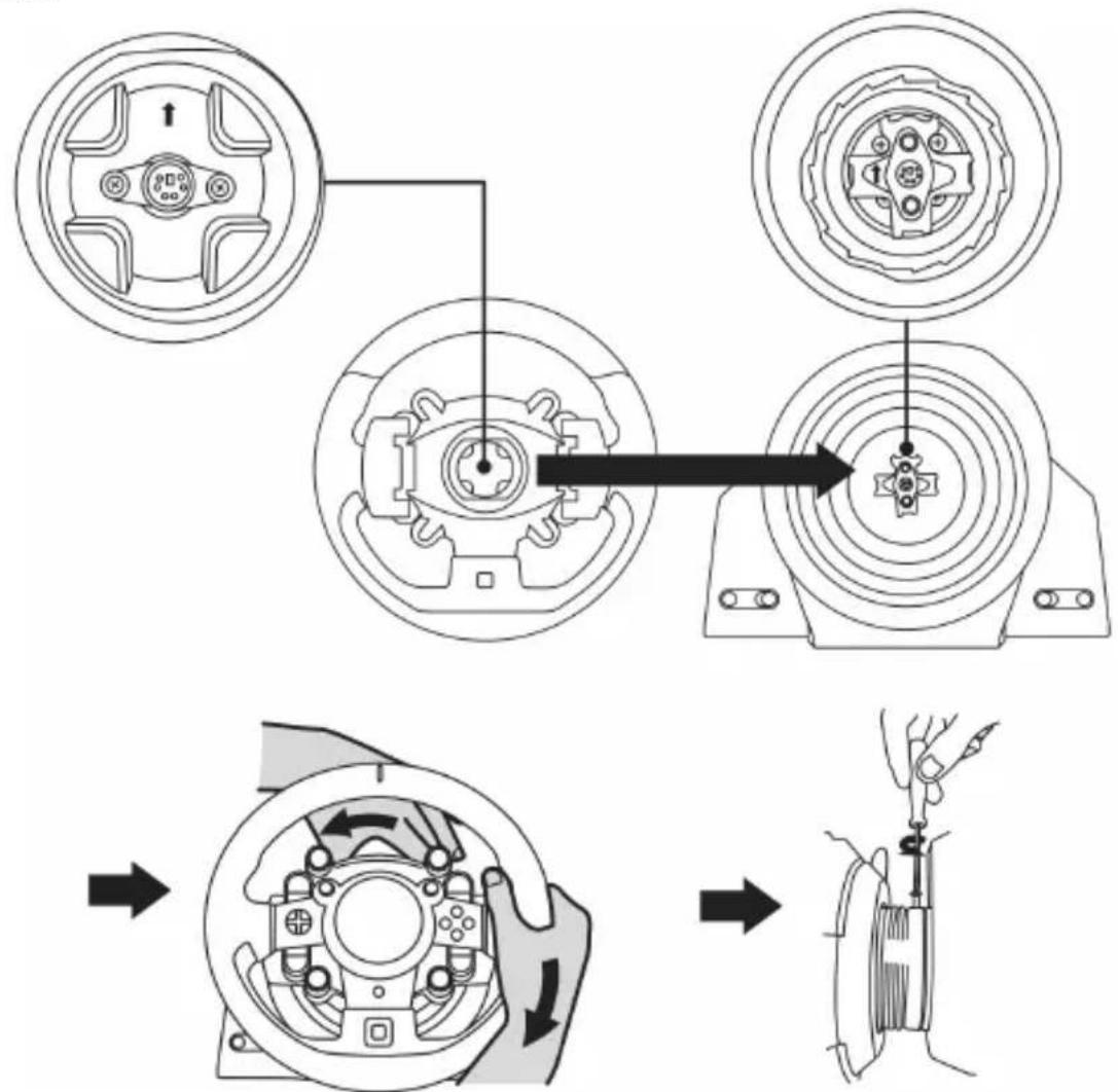
flowchart
graph TD
    A["Wheel rim"] --> B["Actuator"]
    B --> C["Motor"]
    style A fill:#f9f,stroke:#333
    style B fill:#ccf,stroke:#333
    style C fill:#cfc,stroke:#333
Once you have installed the wheel, rotate it 180^ (when facing the wheel, the GT logo should be upside down) to access the small attachment screw located on the ring of the Thrustmaster Quick Release (15) device. Use a large Phillips screwdriver to tighten the small attachment screw (do not use excessive force), turning it clockwise.
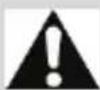
When using a Philips screwdriver, ensure NOT to use excessive force when tightening the small attachment screw!
Stop turning the screw as soon as you feel some resistance.
ATTACHING THE RACING WHEEL
Attaching the racing wheel's base to a cockpit
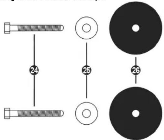
24 2 M6-type hexagon head/Phillips-head bolts
25 2 washers
26 2 mounting discs (metal on one side, and textured rubber on the other)


natural_image
Diagram showing a device component before and after transformation, with no visible text or symbols.- Position the washers (25) on the metal sides of the mounting discs (26), and insert the M6-type hexagon head/Phillips-head bolts (24).
- Place the racing wheel's base on the cockpit shelf.
- Using a 10 mm wrench key or a Phillips-head screwdriver, screw the cockpit mounting kit into the cockpit shelf and into the 2 small screw threads located on the underside of the wheel.
ATTENTION:
- Do not remove the foam pads located on the underside of the racing wheel's base! The foam pads amplify the effects of the T-DFB system when the wheel is attached.
- The textured rubber side of the mounting discs (26) must imperatively be positioned facing the cockpit shelf = never position the metal side facing the cockpit shelf.
Attaching the racing wheel to a table or a desktop
- Place the racing wheel on a table or any other horizontal, flat and stable surface.
- Insert the fastening screw (14) in the attachment system (13), then tighten the device by turning the screw counterclockwise, so that it feeds into the large threaded hole (12) located beneath the racing wheel, until the wheel is perfectly stable.
ALWAYS NEVER
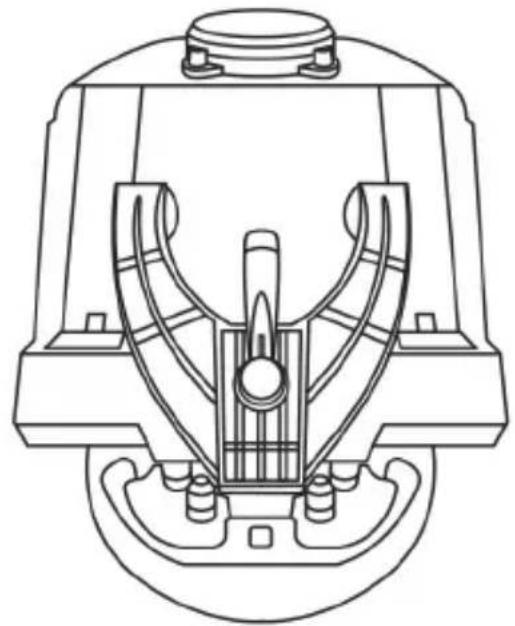
natural_image
Technical line drawing of a mechanical device with internal components and mounting feet (no text or symbols)
natural_image
Technical line drawing of a mechanical component with no visible text or symbolsWARNING:
- Never tighten the screw alone, without the attachment system in place (this could damage the racing wheel).
- Do not remove the foam pads located on the underside of the racing wheel's base! The foam pads amplify the effects of the T-DFB system when the wheel is attached.
| ATTACHMENT / REMOVAL | DIRECTION |
| To tighten:Turn the screw anticlockwise | |
| To release:Turn the screw clockwise | |
SETTING UP THE RACING WHEEL FOR PLAYSTATION®4
- Connect the pedal set to its connector (19) located at the rear of the racing wheel's base.
- Connect the T-TURBO power supply (21) to its connector (17).
- Connect the power supply cable (22) to the T-TURBO power supply, and plug the cable into an electrical outlet with the same voltage.
- Set the USB sliding switch (11) to the "OTHER" or "GT" position, depending on the PS4™ game you are using.
- Connect the removable USB cable (23) to its connector (18) and to one of the USB ports on the PS4 ^™ system.
- Once your PS4 ^TM system is powered on, your racing wheel will calibrate itself.
- Press the PS button (9) on the racing wheel, and log in to your Sony Entertainment Network account in order for your wheel to be functional.
You are now ready to play!
Important notes:
- Don't forget to press the PS button (9) on the racing wheel, in order for your wheel to be functional.
- The USB sliding switch (11) on the wheel's base must always be set to the proper position ("OTHER" or "GT") before connecting the racing wheel's USB cable to your system.
To change the sliding switch's position: disconnect the USB cable, and then set the switch to the appropriate position before reconnecting the USB cable to the system. - The list of PlayStation®4 games compatible with the T-GT (along with the required position for the USB sliding switch (11) according to the game you are using) is available here: http://support.thrustmaster.com (in the Racing Wheels/T-GT section). This list is updated regularly.
USB SLIDING SWITCH (11) IN THE "OTHER" POSITION
FOR PS4™ GAMES APART FROM GT SPORT
When the USB sliding switch (11) is set to the "OTHER" position:
* The wheel is recognized in most games as a T300 RS wheel.
* The 4 rotary selectors with Push function (5) are not functional.
* The 2 mini-sticks (6) are not functional.
* The Force Feedback system is functional, but the T-DFB effects system (16) is not.
USB SLIDING SWITCH (11) IN THE "GT" POSITION
FOR THE GAME GT SPORT (AND OTHER FUTURE GT GAMES)
When the USB sliding switch (11) is set to the "GT" position:
* The wheel is recognized as a T-GT wheel.
* The 4 rotary selectors with Push function (5) are functional.
* The 2 mini-sticks (6) are functional.
* The Force Feedback system, and the T-DFB effects system (16), are both functional at the same time. In the GT Sport game's options, the power level of each system can be adjusted independently.
AUTOMATIC RACING WHEEL AND PEDAL SET CALIBRATION
The wheel automatically self-calibrates when you plug the racing wheel into an electrical outlet and connect the racing wheel's USB connector to the system.
During this phase, the racing wheel will rotate quickly towards the left and the right, covering a 1080 degree angle, before stopping at the center.

WARNING:
Never touch the racing wheel during the self-calibration phase! (This could result in improper calibration and/or personal injuries.)
AUTOMATIC CALIBRATION OF THE PEDAL SET
Never connect the pedal set to the racing wheel's base (or disconnect it from the base) when it is connected to the system or during gameplay (this could result in improper calibration).
Always connect the pedal set before connecting the racing wheel to the system.
Once the racing wheel's calibration is complete and the game has been started, the pedals are automatically calibrated after a few presses.

WARNING:
Never press the pedals during the racing wheel's self-calibration phase or while a game is loading!
(This could result in improper calibration.)
If your racing wheel and/or pedal set do not function correctly, or if they seem to be improperly calibrated:
Power off your system and completely disconnect the racing wheel. Then reconnect all cables (including the power supply cable and the pedal set), and restart your system and your game.
INTERNAL COOLING SYSTEM FOR THE WHEEL'S BASE
The internal cooling system for the wheel's base
- starts working when the wheel is powered on.
- switches off after a few minutes of inactivity when the internal temperature cools down to a low level.
- switches on again when you use the wheel.
MODE BUTTON AND INDICATOR LIGHT (10)
MODE button for the pedal set
You can electronically swap the accelerator and clutch pedals.
To do so, simply press the MODE button (10) for 2 seconds.
The racing wheel's internal memory stores whether the pedals have been swapped around or not.
| GAS AND CLUTCH PEDALS | Color of the MODE indicator light (10) |
| NORMAL | RED |
| SWAPPED AROUND | GREEN |
Other information regarding the MODE button
To learn more about the MODE button and indicator light, please visit http://support.thrustmaster.com. Click Racing Wheels / T-GT, and then select Manual or FAQ.
HELP FILES AND FAQs (NOT INCLUDED IN THIS MANUAL)
Please visit http://support.thrustmaster.com. Click Racing Wheels / T-GT, and then select Manual or FAQ.
SETTING UP THE RACING WHEEL FOR PC\*
UPDATING YOUR RACING WHEEL'S FIRMWARE
*PC compatibility not tested nor endorsed by Sony Interactive Entertainment, Inc.
For more information, visit http://support.thrustmaster.com.
T-GT EDITION PEDAL SET

natural_image
Line drawing of a device with three speakers on top (no text or symbols)TECHNICAL FEATURES
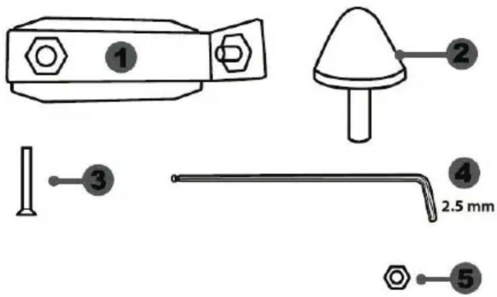
1 Metal support for conical stop (not installed by default)
2 Conical stop
3 Attachment screw for metal support
4 2.5 mm Allen key (included)
5 Position adjustment nut for conical stop

6 Metal pedal arm
7 Plastic head support
8 Metal pedal head
WARNING
Before using this product, be sure to read these instructions carefully and save them for future reference.

For safety reasons, never use the pedal set with bare feet or while wearing only socks on your feet.
THRUSTMASTER® DISCLAIMS ALL RESPONSIBILITY IN THE EVENT OF INJURY RESULTING FROM USE OF THE PEDAL SET WITHOUT SHOES.

Warning – Pedal set pinching hazard during gaming sessions
* Keep the pedal set out of the reach of children.
* During gaming sessions, never place your fingers or thumbs on or near the sides of the pedals.
* During gaming sessions, never place your fingers or thumbs on or near the rear base of the pedals.
* During gaming sessions, never place your fingers or thumbs on or near the front base of the pedals.

AUTOMATIC CALIBRATION OF PEDALS

IMPORTANT:
- Never connect or disconnect the pedal set from the base of the wheel when the wheel is connected to a PS4 ^™ system or to a PC, or during gaming sessions, to avoid calibration problems.
= Always connect the pedal set to the wheel before connecting the wheel to a PS4 ^TM system or to a PC. - Once the wheel has self-calibrated and the game has started, the pedals automatically calibrate themselves after being pressed a few times.
- Never press on the pedals when the wheel is self-calibrating or when your game is starting up, to avoid calibration problems.
- If the pedals are not functioning correctly or appear to be improperly calibrated, power off your system, completely disconnect your wheel, then reconnect all of the cables (including the power supply cable and the pedal set cable), power the system back on and restart your game.
ATTACHING THE PEDAL SET TO A COCKPIT
- Attach the pedal set using the small screw threads located on the underside of the pedal set.
- Screw two M6 screws (not included) into the cockpit's pedal support plate and into the two small screw threads located on the underside of the pedal set.
Important: The length of the two M6 screws must not exceed the thickness of the cockpit's pedal support plate plus an additional 10 mm, to avoid damaging the pedal set's internal components.
ADJUSTING THE PEDAL SET
Each of the three pedals includes:
- A metal head (8) with multiple perforations (nine for the accelerator – two for the brake – six for the clutch).
- A plastic head support (7) (placed between the head and the arm) with four perforations.
- A metal pedal arm (6) with four perforations.

ATTENTION: To avoid any calibration problems, be sure to always disconnect your wheel's USB cable from the PS4™ system before making any adjustments to your pedal set.
Adjusting the HEIGHT of the 3 pedals
- Using the included 2.5 mm Allen key (4), unscrew the two screws holding the metal head (8) and its support (7) in place.
- Select your preferred height position, then replace and re-tighten the screws so that the metal head (8) and its support (7) are held firmly in place.
Examples illustrating the accelerator pedal:

natural_image
Diagram showing two mechanical components with a downward arrow indicating motion or change (no text or symbols)Low position

natural_image
Diagram showing two identical mechanical components with a directional arrow, no text or symbols presentHigh position
Adjusting the SPACING of the accelerator pedal and the clutch pedal
- Using the included 2.5 mm Allen key (4), unscrew the two screws holding the metal head (8) and its support (7) in place.
- Select your preferred position (to the left, centered, or to the right), then replace and re-tighten the screws so that the metal head (8) and its support (7) are held firmly in place.
Examples illustrating the clutch pedal:
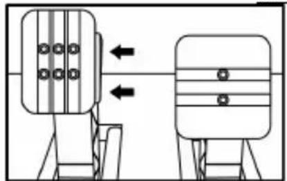
natural_image
Diagram showing two mechanical components with arrows indicating direction, no text or symbols presentLeft position
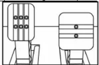
natural_image
Two identical mechanical components with vertical bars and circular holes, mounted on support frames (no text or symbols)Centered position (default)

natural_image
Diagram showing two mechanical components with arrows indicating direction of movement (no text or symbols)Right position
Number of possible spacing positions per pedal:
- Three for accelerator pedal
- Three for clutch pedal
Adjusting the INCLINATION of the 3 pedals
- Using the included 2.5 mm Allen key (4), unscrew the two screws holding the metal head (8) and its support (7) in place.
- Turn the plastic head support (7) 180°, then replace and re-tighten the screws so that the metal head (8) and its support (7) are held firmly in place.
Examples illustrating the accelerator pedal:

natural_image
Diagram of a mechanical structure with a triangular frame and an arrow indicating upward motion (no text or symbols)Less inclined position
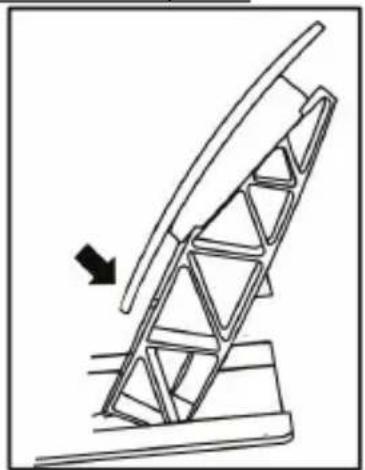
natural_image
Diagram of a mechanical structure with an arrow indicating direction, no text or symbols presentMore inclined position (default)
Number of possible inclination positions per pedal:
- Two for accelerator pedal
- Two for brake pedal
- Two for clutch pedal
Installing the conical stop ("CONICAL RUBBER BRAKE" mod)
This modification (or "mod") is not essential, and is not installed by default. This means that the brake pedal functions perfectly even if the mod is not installed.
This mod lets you experience a different feeling and resistance when braking.
It's up to you whether or not to install it, depending on your own preferences.
- Screw the conical stop (2) onto its metal support (1).
- Screw the position adjustment nut (5) onto the bottom (onto the conical stop's screw thread).

- Position the unit at the back of the brake pedal's arm.
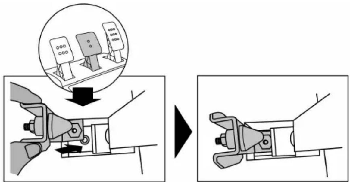
- Using the included 2.5 mm Allen key (4), attach the unit using the attachment screw (3) and the small central screw thread located on the underside of the pedal set.

natural_image
Diagram showing a hand holding a tool inside a circular frame with an arrow indicating rotation (no text or symbols)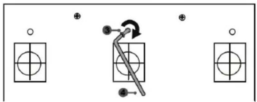
flowchart
graph TD
    A["○"] --> B["○"]
    C["⊕"] --> D["○"]
    E["●"] --> F["○"]
    G["⊕"] --> H["○"]
    I["●"] --> J["○"]
    K["●"] --> L["○"]
    M["●"] --> N["○"]
    O["●"] --> P["○"]
    Q["●"] --> R["○"]
    S["●"] --> T["○"]
    U["●"] --> V["○"]
    W["●"] --> X["○"]
    Y["●"] --> Z["○"]
    AA["●"] --> AB["○"]
    AC["●"] --> AD["○"]
    AE["●"] --> AF["○"]
    AG["●"] --> AH["○"]
    AI["●"] --> AJ["○"]
    AK["●"] --> AL["○"]
    AM["●"] --> AN["○"]
    AO["●"] --> AP["○"]
    AQ["●"] --> AR["○"]
    AS["●"] --> AT["○"]
    AU["●"] --> AV["○"]
    AW["●"] --> AX["○"]
The "CONICAL RUBBER BRAKE" mod is now installed!
Adjusting the brake pedal's RANGE of travel and STRENGTH of resistance
By slightly unscrewing the nut (5), you can further strengthen the resistance of the brake pedal by moving the conical stop (2) closer to the back of the pedal's arm (if necessary, use a 14 mm wrench or pliers to re-tighten the nut and maintain the selected position). The closer the conical stop is positioned to the back of the pedal's arm, the greater the strength of resistance will be.
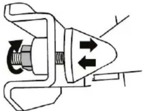
natural_image
Mechanical component diagram showing a valve mechanism with directional arrows (no text or symbols)Note: When the conical stop is very close to the back of the brake pedal's arm, you may experience difficulties in reaching the maximum calibration value. Should that be the case:
* Slowly, press very hard on the brake pedal so as to reach the maximum value (if necessary, stand very briefly on the pedal – just for a second), then release the pressure; or else
* Move the conical stop a bit farther away from the back of the brake pedal's arm.
CONSUMER WARRANTY INFORMATION
Worldwide, Guillemot Corporation S.A., whose registered office is located at Place du Granier, B.P. 97143, 35571 Chantepie, France (hereinafter "Guillemot") warrants to the consumer that this Thrustmaster product shall be free from defects in materials and workmanship, for a warranty period which corresponds to the time limit to bring an action for conformity with respect to this product. In the countries of the European Union, this corresponds to a period of two (2) years from delivery of the Thrustmaster product. In other countries, the warranty period corresponds to the time limit to bring an action for conformity with respect to the Thrustmaster product according to applicable laws of the country in which the consumer was domiciled on the date of purchase of the Thrustmaster product (if no such action exists in the corresponding country, then the warranty period shall be one (1) year from the original date of purchase of the Thrustmaster product).
Notwithstanding the above, rechargeable batteries are covered by a warranty period of six (6) months from the date of original purchase.
Should the product appear to be defective during the warranty period, immediately contact Technical Support, who will indicate the procedure to follow. If the defect is confirmed, the product must be returned to its place of purchase (or any other location indicated by Technical Support).
Within the context of this warranty, the consumer's defective product shall, at Technical Support's option, be either replaced or returned to working order. If, during the warranty period, the Thrustmaster product is subject to such reconditioning, any period of at least seven (7) days during which the product is out of use shall be added to the remaining warranty period (this period runs from the date of the consumer's request for intervention or from the date on which the product in question is made available for reconditioning, if the date on which the product is made available for reconditioning is subsequent to the date of the request for intervention). If permitted under applicable law, the full liability of Guillemot and its subsidiaries (including for consequential damages) is limited to the return to working order or the replacement of the Thrustmaster product. If permitted under applicable law, Guillemot disclaims all warranties of merchantability or fitness for a particular purpose.
This warranty shall not apply: (1) if the product has been modified, opened, altered, or has suffered damage as a result of inappropriate or abusive use, negligence, an accident, normal wear, or any other cause unrelated to a material or manufacturing defect (including, but not limited to, combining the Thrustmaster product with any unsuitable element, including in particular power supplies, rechargeable batteries, chargers, or any other elements not supplied by Guillemot for this product); (2) if the product has been used for any use other than home use, including for professional or commercial purposes (game rooms, training, competitions, for example); (3) in the event of failure to comply with the instructions provided by Technical Support; (4) to software, said software being subject to a specific warranty; (5) to consumables (elements to be replaced over the product's lifespan: disposable batteries, audio headset or headphone ear pads, for example); (6) to accessories (cables, cases, pouches, bags, wrist-straps, for example); (7) if the product was sold at public auction.
This warranty is nontransferable.
The consumer's legal rights with respect to laws applicable to the sale of consumer goods in his or her country are not affected by this warranty.
Additional warranty provisions
During the warranty period, Guillemot shall not provide, in principle, any spare parts, as Technical Support is the only party authorized to open and/or recondition any Thrustmaster product (with the exception of any reconditioning procedures which Technical Support may request that the consumer carry out, by way of written instructions – for example, due to the simplicity and the lack of confidentiality of the reconditioning process – and by providing the consumer with the required spare part(s), where applicable).
Given its innovation cycles and in order to protect its know-how and trade secrets, Guillemot shall not provide, in principle, any reconditioning notification or spare parts for any Thrustmaster product whose warranty period has expired.
In the United States of America and in Canada, this warranty is limited to the product's internal mechanism and external housing. In no event shall Guillemot or its affiliates be held liable to any third party for any consequential or incidental damages resulting from the breach of any express or implied warranties. Some States/Provinces do not allow limitation on how long an implied warranty lasts or exclusion or limitation of liability for consequential or incidental damages, so the above limitations or exclusions may not apply to you. This warranty gives you specific legal rights, and you may also have other rights which vary from State to State or Province to Province.
Liability
If permitted under applicable law, Guillemot Corporation S.A. (hereinafter "Guillemot") and its subsidiaries disclaim all liability for any damages caused by one or more of the following: (1) the product has been modified, opened or altered; (2) failure to comply with assembly instructions; (3) inappropriate or abusive use, negligence, an accident (an impact, for example); (4) normal wear; (5) the use of the product for any use other than home use, including for professional or commercial purposes (game rooms, training, competitions, for example). If permitted under applicable law, Guillemot and its subsidiaries disclaim all liability for any damages unrelated to a material or manufacturing defect with respect to the product (including, but not limited to, any damages caused directly or indirectly by any software, or by combining the Thrustmaster product with any unsuitable element, including in particular power supplies, rechargeable batteries, chargers, or any other elements not supplied by Guillemot for this product).
DECLARATION OF CONFORMITY
CANADIAN COMPLIANCE NOTICE: this Class B digital apparatus meets all requirements of the Canadian Interference-Causing Equipment Regulations.
USA COMPLIANCE NOTICE: this equipment has been tested and found to comply with the limits for a Class B digital device, pursuant to Part 15 of the FCC rules. Operation is subject to the following two conditions:
(1) This device may not cause harmful interference, and
(2) This device must accept any interference received, including interference that may cause undesired operation.
These limits are designed to provide reasonable protection against harmful interference in a residential installation. This equipment generates, uses and can radiate radio frequency energy and, if not installed and used in accordance with the instructions, may cause harmful interference to radio communications. However, there is no guarantee that interference will not occur in a particular installation. If this equipment does cause harmful interference to radio or television reception, which can be determined by turning the equipment on and off, the user is encouraged to try to correct the interference by one or more of the following measures:
- Reorient or relocate the receiving antenna.
- Increase the separation between the equipment and receiver.
- Connect the equipment into an outlet on a circuit different from that to which the receiver is connected.
- Consult the dealer or an experienced radio/TV technician for help.
THRUSTMASTER®
TECHNICAL SUPPORT
http://support.thrustmaster.com

natural_image
Three black icons: a lowercase 'i' in a circle, an envelope symbol, and a telephone handset (no text or labels)COPYRIGHT
© 2017 Guillemot Corporation S.A. All rights reserved. Thrustmaster® is a registered trademark of Guillemot Corporation S.A.
“”, “PlayStation”, “PS4” and “△OX□” are registered trademarks of Sony Interactive Entertainment Inc. Gran Turismo and Gran Turismo logo are registered trademarks or trademarks of Sony Interactive Entertainment Inc. All rights reserved.
All other trademarks and brand names are hereby acknowledged and are property of their respective owners. Illustrations not binding. Contents, designs and specifications are subject to change without notice and may vary from one country to another. Made in China.
TouchSense® technology licensed from Immersion Software Ireland Limited. Protected by one or more of the U.S. Patents found at the following address: www.immersion.com/patent-marking.html, and other patents pending.
ENVIRONMENTAL PROTECTION RECOMMENDATION
Please adhere to local recycling laws for electrical and electronic equipment.
Retain this information. Colors and decorations may vary.
Plastic fasteners and adhesives should be removed from the product before it is used.
www.thrustmaster.com
CE FC
immersion.

- WARNING:
- PLUGGING THE WHEEL INTO AN ELECTRICAL OUTLET: PLEASE READ CAREFULLY!
- WARNING
- Warning – Electrical shock
- Air vents
- Warning – Injuries due to Force Feedback and repeated movements
- Warning – Injuries due to Force Feedback and repeated movements (continued)
- Warning – Pedal set pinch hazard when playing
- Warning – Pedal set pinch hazard when not playing
- UPDATING YOUR RACING WHEEL'S FIRMWARE
- Important note:
- INSTALLING THE WHEEL ON ITS BASE
- ATTACHING THE RACING WHEEL
- Attaching the racing wheel's base to a cockpit
- ATTENTION:
- Attaching the racing wheel to a table or a desktop
- SETTING UP THE RACING WHEEL FOR PS4™
- Important notes:
- USB SLIDING SWITCH (11) IN THE "OTHER" POSITION
- FOR PS4™ GAMES APART FROM GT SPORT
- USB SLIDING SWITCH (11) IN THE "GT" POSITION FOR THE GAME GT SPORT (AND OTHER FUTURE GT GAMES)
- SETTING UP THE RACING WHEEL FOR PC\*
- AUTOMATIC RACING WHEEL AND PEDAL SET CALIBRATION
- AUTOMATIC CALIBRATION OF THE PEDAL SET
- INTERNAL COOLING SYSTEM FOR THE WHEEL'S BASE
- MODE BUTTON AND INDICATOR LIGHT (10)
- MODE button for the pedal set
- Other information regarding the MODE button
- HELP FILES AND FAQs
- T-GT EDITION PEDAL SET
- Warning – Pedal set pinching hazard during gaming sessions
- AUTOMATIC CALIBRATION OF PEDALS
- ATTACHING THE PEDAL SET TO A COCKPIT
- ADJUSTING THE PEDAL SET
- Adjusting the HEIGHT of the 3 pedals
- Adjusting the SPACING of the accelerator pedal and the clutch pedal
- Adjusting the INCLINATION of the 3 pedals
- Installing the conical stop ("CONICAL RUBBER BRAKE" mod)
- Adjusting the brake pedal's RANGE of travel and STRENGTH of resistance
- CONSUMER WARRANTY INFORMATION
- Additional warranty provisions
- Liability
- COPYRIGHT
- ENVIRONMENTAL PROTECTION RECOMMENDATION
- T-GT
- ATTENTION :
- INFORMATIONS RELATIVES A LA GARANTIE AUX CONSOMMATEURS
- ACHTUNG!
- ACHTUNG:
- T-GT EDITION-PEDALSET
- EINBAU DES PEDALSETS IN EIN COCKPIT
- ANPASSEN DES PEDALSETS
- WAARSCHUWING:
- USB-SCHUIFSCHAKELAAR (11) IN DE STAND "OTHER"
- VOOR PS4™-GAMES MET UITZONDERING VAN GT SPORT
- T-GT EDITION-PEDAALSET
- WAARSCHUWING
- DE PEDAALSET AAN EEN COCKPIT BEVESTIGEN
- ATTENZIONE:
- ADVERTENCIA:
- ATENCIÓN:
- ATENÇÃO:
- FIXAR O CONJUNTO DE PEDAIS A UM COCKPIT
- ВНИМАНИЕ!
- АВТОРСКИЕ ПРАВА
- ΠΡΟΕΙΔΟΠΟΙΗΣΗ:
- UYARI:
- T-GT EDITION PEDAL SETI
- TELİF HAKKI
- OSTRZEŻENIE:
- UWAGA:
- PRAWA AUTORSKIE
- SETTING UP THE RACING WHEEL FOR PLAYSTATION®4
- USB SLIDING SWITCH (11) IN THE "GT" POSITION
- FOR THE GAME GT SPORT (AND OTHER FUTURE GT GAMES)
- SETTING UP THE RACING WHEEL FOR PC
- You are now ready to play!
- General notes:
- HELP FILES AND FAQs (NOT INCLUDED IN THIS MANUAL)
- IMPORTANT:
- DECLARATION OF CONFORMITY
- THRUSTMASTER®
- TECHNICAL SUPPORT
- ATTENTION !:
- 警告:
- ペダルの自動調整
- 重要:
- 警告 — 玩游戏时踏板组夹住危险
- 技术特性
- 警告
- 踏板自动校准
- 重要说明:
- 调节油门踏板和离合器踏板的间距
- 调节三个踏板的倾角
- 注意-遊玩時請小心別被腳踏板組夾傷
- 注意-非遊玩時亦請小心別被腳踏板夾傷
- 自動校準腳踏板組
- 重要提示:
- 調節油門踏板和離合器踏板的間距
- 調節三個踏板的傾角
- 安裝錐形塞(「錐形橡膠煞車器」修改器)
- 調整煞車踏板的行動範圍及阻力強度
- 기술적 특징
- 페달 자동 보정
- 중요:
- 개의 폐달 '경사' 조정
Brand : THRUSTMASTER
Model : T.Racing Scuderia Ferrari Edition
Category : Headphones