
200M - Powerline Adapter NPG - Free user manual and instructions
Find the device manual for free 200M NPG in PDF.
| Product Type | Powerline CPL Adapter |
| Brand | NPG |
| Model | 200M |
| Dimensions (L × W × H) | 130.5 mm × 69 mm × 79 mm |
| Weight | 233 g |
| Power Supply | 100-240 V AC, 50/60 Hz, integrated socket 16 A max (220 V) or 20 A max (110 V) |
| Power Consumption | 3.5 W |
| Powerline Ethernet Speed | Up to 200 Mbit/s |
| Network Protocol | HomePlug AV 1.0, compatible with HomePlug 1.0 |
| Modulation | OFDM with 1024/256/64/16/8-QAM, QPSK, BPSK, ROBO |
| Encryption | 128-bit AES |
| Main Features | Data transmission via powerline (CPL), integrated female socket with noise filter, private network creation via Security button, compatible with IPTV, VoIP, HD/SD video |
| Interfaces | 1 RJ45 Ethernet port (10/100 Mbps), integrated power socket (input and output) |
| LED Indicators | Power (green), Ethernet (green blinking activity), Data (green blinking PLC activity) |
| Control Buttons | Reset (factory reset), Security (private network configuration via NMK) |
| Kit Contents | 2 Powerline adapters, 2 RJ45 Ethernet cables, 1 utility CD-ROM |
| Compatible Operating Systems | Windows 98SE, 2000, ME, XP (32/64-bit), Vista (32/64-bit), Windows 7 (32/64-bit) |
| Minimum System Requirements | Intel Pentium III 2 GHz, 128 MB RAM, 20 MB disk space, Fast Ethernet network card |
| Operating Temperature | 0 to 45 °C |
| Storage Temperature | -20 to 70 °C |
| Operating Humidity | 10% to 90% (non-condensing) |
| Cleaning and Maintenance | Unplug before cleaning. Use a damp cloth. Do not use liquid or aerosol cleaners. |
| Safety | Do not use an extension cord between the adapter and the outlet. Do not plug into a power strip or surge protector. Avoid sources of electrical noise (charger, halogen light). Unplug in case of liquid, rain, or malfunction. |
| Certifications | CE, UL, FCC Part 15 Class B, RoHS |
Frequently Asked Questions - 200M NPG
User questions about 200M NPG
0 question about this device. Answer the ones you know or ask your own.
Ask a new question about this device
Download the instructions for your Powerline Adapter in PDF format for free! Find your manual 200M - NPG and take your electronic device back in hand. On this page are published all the documents necessary for the use of your device. 200M by NPG.
USER MANUAL 200M NPG
Ethernet Power Line Adapter User Manual
English 01
Espanol P.20
Català P. 39
Français P. 58
Portugués P. 77

Ethernet Power Line Adapter User Manual
English
INDEX
1 INTRODUCTION 3
1.1 PRODUCT FEATURE 3
1.2 APPLICATION 3
1.3 SYSTEM REQUIREMENTS 4
1.4 PACKAGE CONTENTS 4
2 SAFETY NOTICE: 4
3 GETTING TO KNOW THE ADAPTER 5
3.1 THE ETHERNET INTERFACE 5
3.2 THE ADAPTER'S BUTTONS 5
3.3 THE ADAPTER'S LEDs 5
4 HOW TO INSTALLATION UTILITY 6
5 HOW TO USE THE UTILITY SOFTWARE 7
5.1 MAIN TAB 7
5.2PRIVACYTAB 9
5.3 DIAGNOSTICS TAB 10
5.4 ABOUT TAB 11
6 HOW TO USE THE NMK PUSHBUTTON 12
6.1 FORMING A HOMEPLUG AV LOGICAL NETWORK 12
6.2 JOINING A NETWORK 13
6.3 LEAVING A NETWORK 14
7 HOW TO IMPROVE THE TRANSMISSION CAPACITY 15
APPENDIX A SPECIFICATIONS 16
APPENDIX B ACRONYMS AND ABBREVIATIONS 17
APPENDIX C ABOUT QOS 18
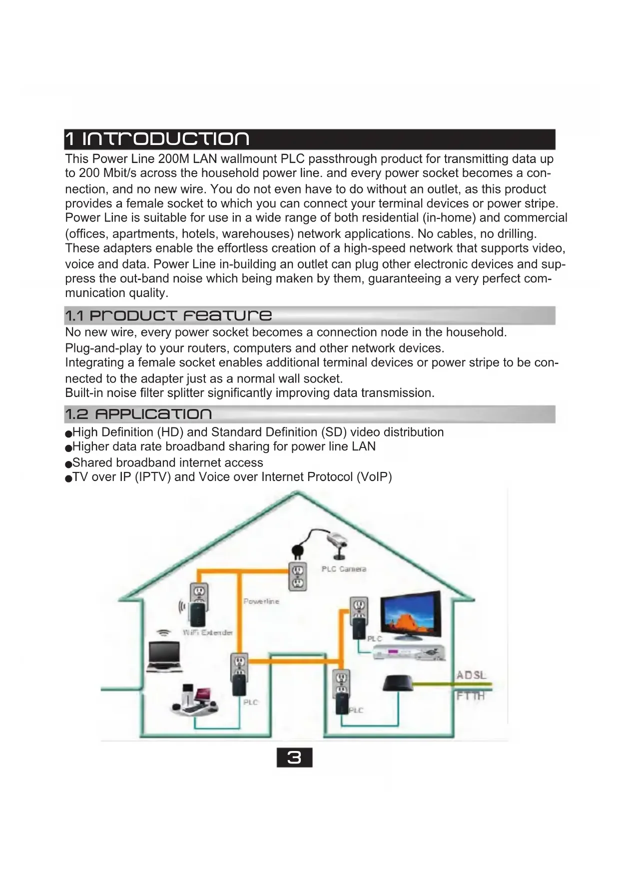
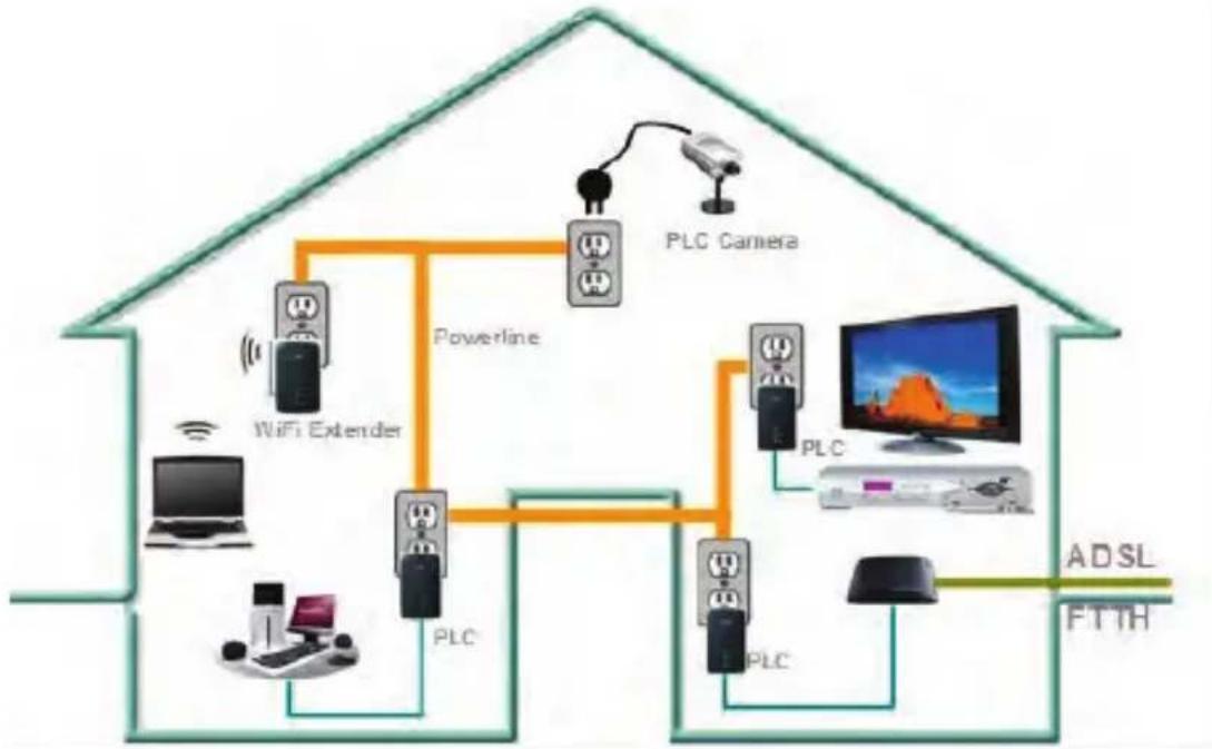
1 INTRODUCTION
This Power Line 200M LAN wallmount PLC passthrough product for transmitting data up to 200 Mbit/s across the household power line. and every power socket becomes a connection, and no new wire. You do not even have to do without an outlet, as this product provides a female socket to which you can connect your terminal devices or power stripe. Power Line is suitable for use in a wide range of both residential (in-home) and commercial (offices, apartments, hotels, warehouses) network applications. No cables, no drilling. These adapters enable the effortless creation of a high-speed network that supports video, voice and data. Power Line in-building an outlet can plug other electronic devices and suppress the out-band noise which being made by them, guaranteeing a very perfect communication quality.
1.1 PRODUCT FEATURE
No new wire, every power socket becomes a connection node in the household.
Plug-and-play to your routers, computers and other network devices.
Integrating a female socket enables additional terminal devices or power stripe to be connected to the adapter just as a normal wall socket.
Built-in noise filter splitter significantly improving data transmission.
1.2 APPLICATION
High Definition (HD) and Standard Definition (SD) video distribution
Higher data rate broadband sharing for power line LAN
- Shared broadband internet access
- TV over IP (IPTV) and Voice over Internet Protocol (VoIP)
1.3 SYSTEM REQUIREMENTS
| Operating System Microsoft Windows 2000 or XP , Vista 32-bit/64-bit, Windows 7 32-bit/64-bit | |
| CPU Intel Pentium III or better, clock rate faster than 2.0GHz recommended | |
| RAM At least 128MB | |
| Screen Resolution Any resolution | |
| Free Disk Space At least 20MB | |
| Network Interface At least one Fast Ethernet (100 Mbps) network card, and Ethernet Cord | |
1.4 Package Contents
-PLC 200AV x 2
CD ROM x1
RJ45 Ethernet cable x 2
2 SAFETY NOTICE
This device is intended for connection to the AC power line. For installation instructions, please refer to the installation section of this guide. The following precautions should be taken when using this product.
- Read all instructions before installing and operating this product.
- Follow all warnings and instructions marked on the product.
- Unplug the device from the wall outlet before cleaning. Use a damp cloth for cleaning. Do not use liquid cleaners or aerosol cleaners.
- Do not operate this product near water.
This product should never be placed near or over a radiator or heat register.
-Do not use an extension cord between the device and the AC power source. - Only a qualified technician should service this product. Opening or removing covers may result in exposure to dangerous voltage points or other risks.
- Do not plug the device into a power strip or surge protector because these devices may consist of filter and impair signal.
- Avoid plugging the device right next to noisy sources such as cell phone charger, Halogen light, noisy desktop computer, vacuum cleaner, etc. this cases result in poor transmission speed.
- Unplug the device from the wall outlet and refer the product to qualified service personnel for the following conditions:
If liquid has been spilled into the product
If the product has been exposed to rain or water
If the product does not operate normally when the operating instructions are followed
If the product exhibits a distinct change in performance
3 GETTING TO KNOW THE ADAPTER
3.1 THE ETHERNET INTERFACE
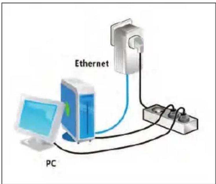
Ethernet : The Ethernet port connects to an Ethernet network cable. The other end of the cable will connect to your computer or other Ethernet-enabled network device.
3.2 THE ADAPTER'S BUTTONS
Reset: The button can restore the factory defaults and reset the device.
Security: The button is used to set the private network name. The detail see chap 6.
3.3 THE ADAPTER'S LEDs
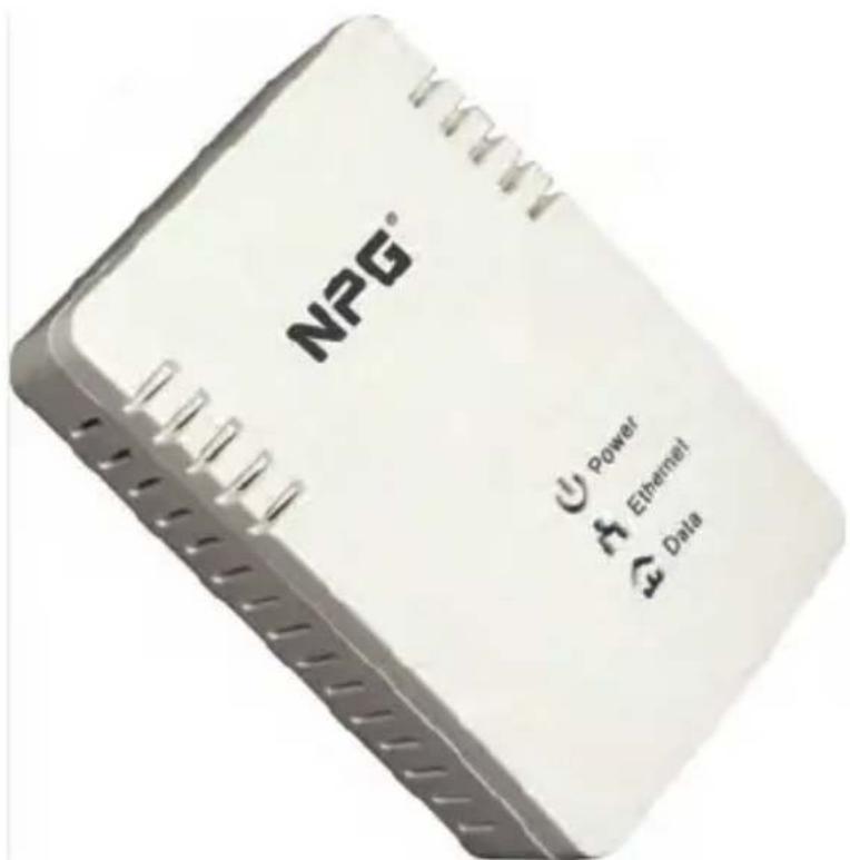
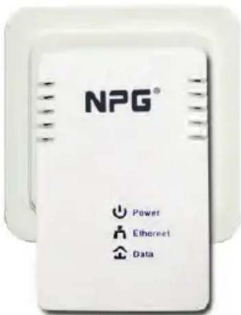
All Adapter's LEDs are located on the front panel, there are 3 LEDs to indicate the adapter's status.
Power: Green, The Power LED lights up when the Adapter is powered on.
Ethernet: Green, The Ethernet LED flashes to indicate activity over the Ethernet connection.
Data: Green, The Data LED flashes to indicate activity over the powerline connection.
4 HOW TO INSTALLATION UTILITY
First step, you need to verify that there is no any other Powerline Utility installed on your computer before installing this utility. If there is another utility installed, please uninstall it and restart your computer.
Second step, please insert the Utility CD-ROM into the computer's CD-ROM drive. then select the "PLC 200AV Utility Installation" folder and clicks the setup.exe. Follow the steps to install the Utility Program. No password or CD-Key is needed.
The installation procedure is similar to the one shown in the next Figures. Click the Next button to continue.
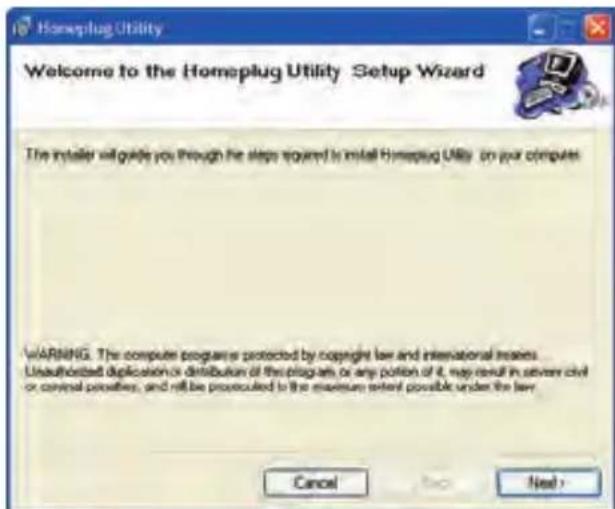
Setup Wizard
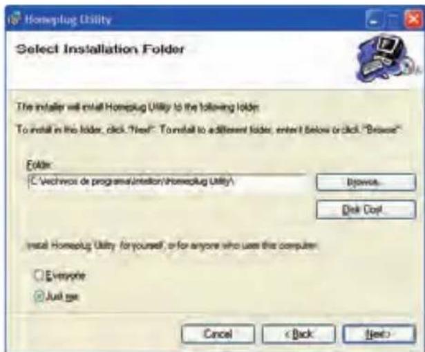
Select Installation Folder
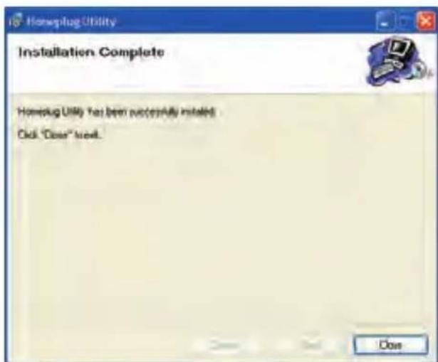
Installation Complete
Click "Close" to complete installation.
5 HOW TO USE THE UTILITY SOFTWARE
5.1 main Tab
The Main screen provides a list of all powerline devices logically connected to the computer when the utility is running.
The top panel shows local HomePlug devices connected to the computer's NIC (Network Interface Card). the user can click the Connect button to its right. Once connected to the local device, the utility will automatically scan the power line periodically for any other HomePlug devices. If no local HomePlug devices are discovered, the status area above the connect button will indicate with a message 'NO HOMEPLUG ADAP- TERS DETECTED'.
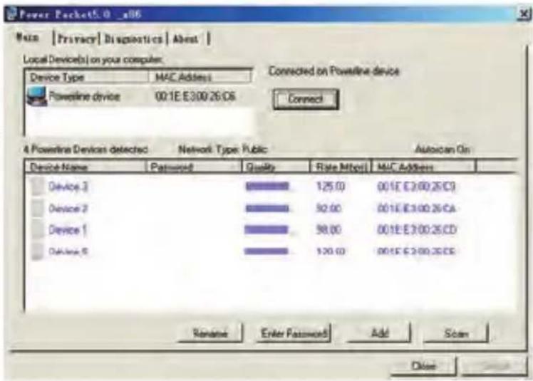
The lower panel displays all the HomePlug remote devices, discovered on the current logical network. The total number of remote devices connected on the same network can be found on top of the Remote device panel. The Network type (Public or Private) is also displayed based on the network status of the local device. The scan status option is displayed on the top right corner above the Remote devices panel showing whether the Autoscan functionality is turned ON or OFF. The following information is displayed for all devices that appear in the lower panel.
Device Name
This column shows the default device name, which may be user re-defined. A user can change the name by either using the rename button or by clicking on the name and editing in-place.
MAC Address
This column shows the Remote device's MAC address.
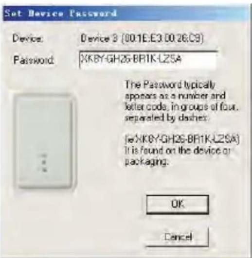
Password
This column by default is blank and "Enter Password" button can be used to enter it.
To set the Password of the device (required when creating a private network), first select the device by clicking on its name in the lower panel and then click on the Enter Password button. A dialog box will appear as shown in Figure 5-2 to type the password. The selected device name is shown above the password field and the password can be verified by hitting the OK button. The Password field accepts the Device password in any case formats, with or without dashed between them.
A confirmation box will appear if the password was entered correctly. If a device was not found, the user will be notified along with the suggestions to resolve common problems. This process might take a few seconds to get completed.
Add
This button is used to add a remote device to the existing network by entering the device password of the device. A dialog box will appear as shown below in Figure 6. The dialog box allows the user to enter both a device name and the password.
A confirmation box will appear if the password was entered correctly and if the device was found in the powerline network. If a device was not found, the user will be notified and suggestions to resolve common problems will be presented.
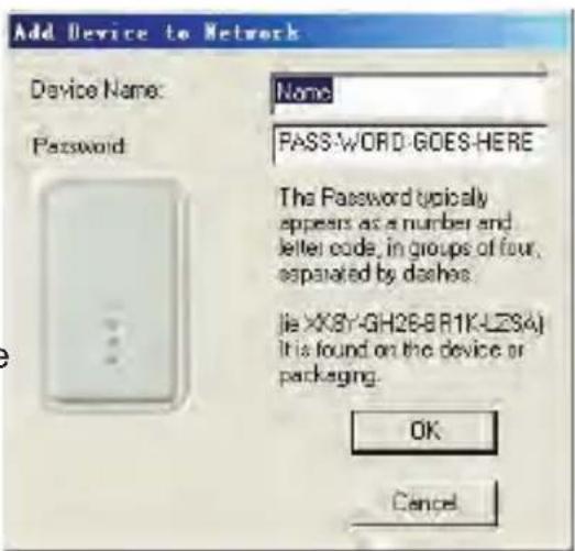
Note: The device must be present on the power line (plugged in) in order for the password to be confirmed and added to the network. If the device could not be located, a warning message will be shown.
Scan
This button is used to perform an immediate search of the HomePlug devices connected to the Powerline network. By default, the utility automatically scans every few seconds and updates the display screen.
5.2 PrivacvTab
The Privacy screen provides the user with an option to maintain security for their logical network and also to select the devices that has to be included in the network.
All Home Plug devices are shipped using a default logical network (network name), which is normally
"Home Plug". The Privacy dialog screen allows user to change to a private network by changing the network name (network password) of devices.
The user can always reset to the Home Plug network (Public) by entering "Home Plug" as the network name or by clicking on the Use Default button.
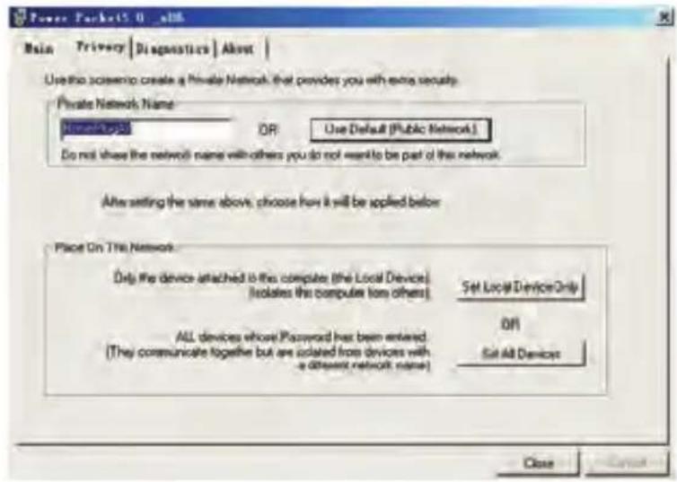
Note: Changing the network name to anything other than HomePlug will show the network type on the main screen as Private.
Set Local Device Only
This button can be used to change the network name (network password) of the local device. If a new network password is entered, all the devices seen on the Main panel prior to this will be no longer present in the new network, effectively making the local devices not to communicate to the devices who were in the old logical network. Devices previously set up with the same logical network (same network name) will appear in the device list afterward selecting this option.
Set All Devices
This button is used to change the logical network of all devices that appear on the Main panel whose Device's Password had been entered for the same logical network. A dialog window will appear to report the success of this operation. For devices whose device password's were not entered, this operation will fail and will report a failure message.
5.3 DIAGNOSTICS TAB
The Diagnostics screen shows System information and a history of all remote devices seen over a period of time.
The Upper panel shows technical data concerning software and hardware present on the host computer which were used to communicate over HomePlug on the Powerline network. It shall include the following:
Operating System Platform/Version
Host Network Name
User Name
MAC Address of all NICs (Network interface card) connected to the host
Identify versions of all Driver DLLs and Libraries used (NDIS) and optionally
HomePlug chipset manufacturer name (Turbo Only devices)
MAC Firmware Version (Turbo Only devices)
MAC addresses of all devices connected locally to the host
Version of the Configuration Utility
Vendor name
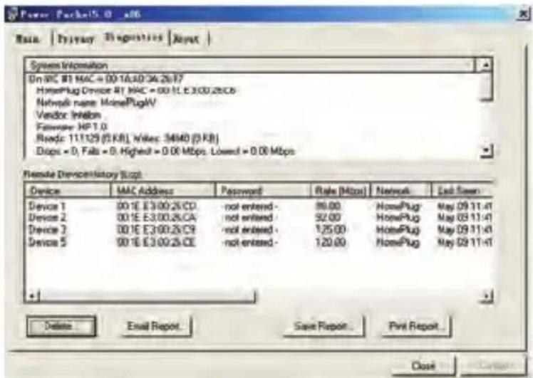
The Lower panel contains a history of all remote devices seen on the computer over a certain period of time. All devices that were on the powerline network are listed here along with a few other parameters. Devices that are active on the current logical network will show a transfer rate in the Rate column; devices on other networks, or devices that may no longer exist are shown with a “?” in the Rate column. The following remote device information is available from the diagnostics screen:
Device Alias Name
Device MAC Address
Device Password
Device Last known rate
Device Last Known Network name
HomePlug chipset manufacturer name
Date device last seen on the network
MAC Firmware Version
The diagnostics information displayed may be saved to a text file for later use, or can be printed for reference for a technical support call. Devices, which are not part of the network anymore, can be deleted using the delete button. A dialog window pops up with a confirmation message if we try to delete a device whose password has been entered.
5.4 ABOUT TAB
The About screen shows the software version and provides a html link to a website, such as www.PowerPacket.com. Clicking on the web address field will open a web browser and take the user directly to the web site.
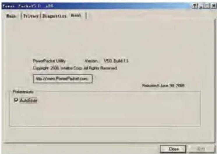
Preferences
The lower part of the panel may display options for turning the auto-scan feature on or off.
6 HOW TO USE THE nMK PUSHBUTTON
This section describes how to add new devices to, or remove old devices from a HomePlug AV logical network (AVLN, both can be accomplished using a NMK pushbutton press.
Operation progress and outcome can be monitored by observing the behavior of the Power LED.
6.1 FORMING a HOMEPLUG AV LOGICAL NETWORK
When two devices with different NMK values are connected to the same powerline, and wants them to form a logical network.
- Press the NMK button on the first device A for less than 3 seconds.
- Press the NMK button on the second device B for less than 3 seconds. The button on B must be pressed within 1 minute
- Wait for connection to complete.
The Power LED on both devices will flash evenly at 1-second intervals until the operation succeeds or fails. It will illuminate steadily on successful completion. If an error occurs, the Power LED on the 'adder' will flash unevenly until the pushbutton on the 'adder' is pressed again or the 'joiner' is reset by holding the pushbuttons down for more than 10 seconds.
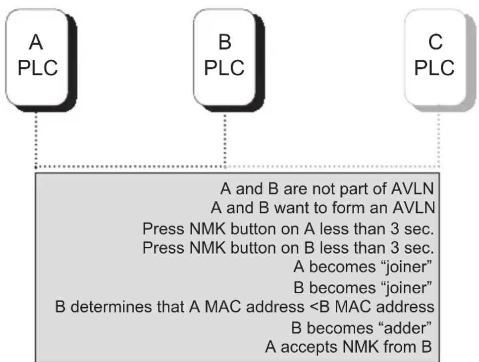
Forming a HomePlug AV logical network
6.2 JOINING a network
In this scenario a network exists, a new device, the 'joiner', wants to join the network. Any device on the existing network can become the 'adder'.
- Press the pushbutton on the 'joiner' for at least 3 seconds.
- Press the pushbutton on any network device for less than 3 seconds, making it the 'adder'. Please press this pushbutton within 1 minute.
- Wait for connection to complete.
The Power LED on both devices will flash at 1-second intervals until the process succeeds or fails. It will illuminate steadily on success. If an error occurs, the Power LED on the 'adder' will flash unevenly until the pushbutton on the 'adder' is pressed again or the 'joiner' is reset by pressing the pushbutton for more than 10 seconds.
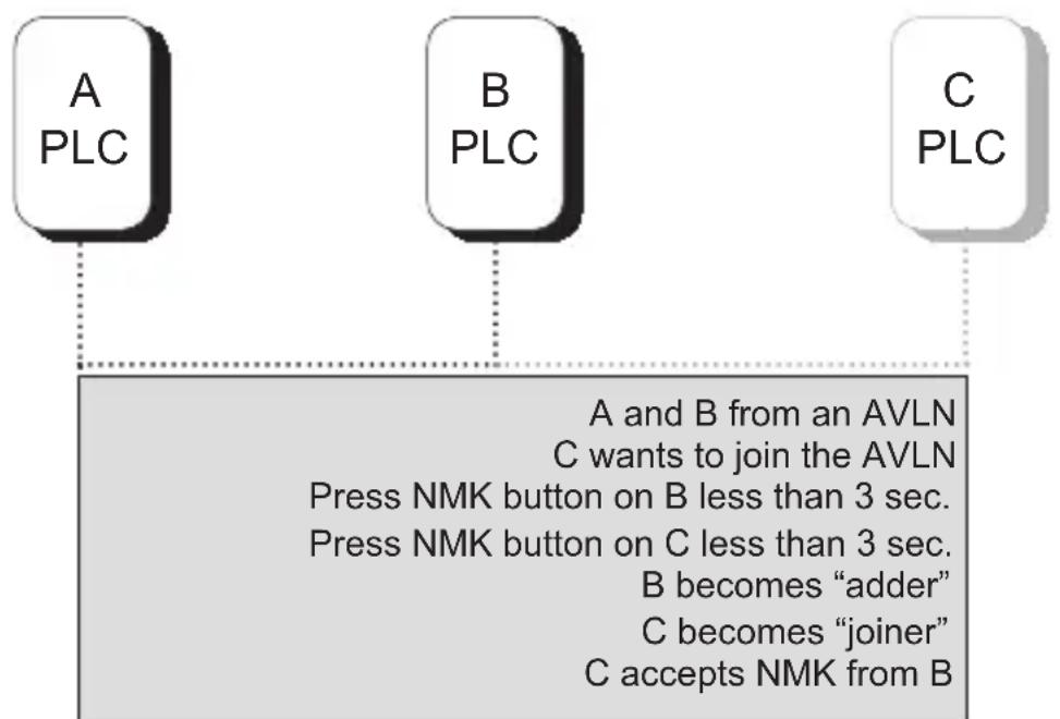
Joining a Network
6.3 Leaving a network
A network exists. The user wants to remove one device, the 'leaver', from that network, for whatever reason. He may want to remove the device from service altogether or have it join another logical network.
- Press the pushbutton on the 'leaver' for at least 10 seconds. The device will reset and restart with a random NMK.
- Wait for reset to complete.
The Power LED on the 'leaver' will momentarily extinguish during reset, flash during restart then illuminate steadily. No errors can occur.
Once the process completes, the user may disconnect the device from the medium or join it to another logical network on the same medium.
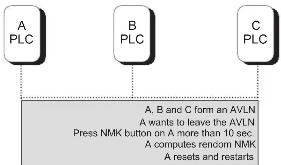
Leaving a Network
? IMPROVE THE TRANSMISSION CAPACITY
It is important to use the PLC product complying with the following "correct rules", because it can significantly improve the transmission capacity of the network.
For the PLC device no female socket, it is recommended to Plug the device directly into a wall socket, not to power stripe.
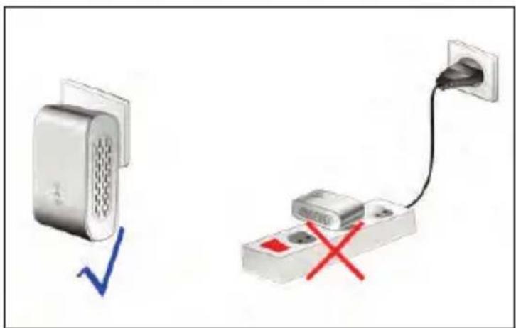
For the PLC device with female socket, you should connect all additional network devices that are connected to a multiple socket to the mains power supply via the electrical socket integrated into the PLC device with female socket. To take full advantage of the filter function, to improve data transmission in the network, always plug the power stripe into the female socket.
| Chipset | Intellon INT6300 |
| Protocol | HomePlug AV 1.0 Co-exists with existing HomePlug 1.0 |
| System Support | Windows 98SE, 2000, ME, XP 32/64 bit and Vista 32/64bit |
| PLC Rate | 200Mb |
| Modulation Band | 2-30MHz |
| Modulation Schemes | Supports1024/256/64/16/8-QAM, QPSK,BPSK and ROBO |
| Encryption | 128 AES |
| Outlet current | 220VAC 16A Maximum, 110VAC 20A Maximum |
| Filter characteristics | -22 dB to -45 dB |
| LED's | Power Ethernet: Ethernet Link and Activity Data: PLC Link and Activity |
| Push Button | Reset: Restore the default factory parameter Security: Set up network password automatically |
| Consumption | 3.5W |
| Operating Temperature | 0° to 45°C |
| Storage Temperature | -20° to 70°C |
| Operating Humidity | 10% to 90% Non-condensing |
| Storage Humidity | 5% to 90% Non-Condensing |
| Input Rating | 100-240 VAC, 50/60Hz |
| Certifications | CE, UL, FCC Part 15 Class B |
| Green Standard | RoHS |
| Physical Characteristics | L×W×H: 130.5mm×69mm×79mm |
| Weight | 233g |
| AVLN | AV In-home Logical Network, the AVLAN is the set of STAs that possess the same network Membership key, every AVLN is managed by a single CCo |
| CCo | Central Coordinator, the CCo is a superset of a STA which provisioning of terminal equipment identifiers and global link identifiers |
| CSMA/CA | Carrier Sense Multiple Access / Collision Avoidance |
| DAK | Device Access Key |
| DM | Device Manager |
| IGMP | Internet Group Management Protocol |
| NEK | Network Encryption Key |
| NID | Network ID (Identification) |
| NMK | Network Membership Key |
| PLC | Power Line Communication |
| PIB | Parameter Information Block |
| STA | Station, a STA in the network with a connection to the power line and being able to source or sink traffic |
| TDMA | Time Division Multiple Access |
| TEI | Terminal Equipment Identifier |
| TOS | Type Of Service |
| VLAN | Virtual Local Area Network |
APPENDIX C
ABOUT QOS
PLC 200AV allows for 4 levels of Channel Access Priority (CAP (0 - 3) ). The 8 levels of VLAN Ethernet tags must be mapped to the 4 levels of CAP priority, where CAP 3 is the highest priority and CAP 0 is the lowest. CAP 3 priority might be used for voice and network management frames, CAP 2 is used for streaming video and music while CAP 1 and CAP 0 are used for data.
Default CAP
The 'Default CAP' group allows for default priority mapping of packets that do not have a VLAN TAG. Settings are available for Unicast (directed to a host).
IGMP - (default CAP 3) - sets the channel access priority for IGMP frames - these are the group management frames, not the stream data
Unicast - (default CAP 1) - sets the default channel access priority for unicast frames not matching any other classification or mapping.
IGMP managed Multicast Stream (Fixed to CAP 2) - sets the default channel access priority for stream data belonging to a snooped IGMP multicast group.
Multicast/Broadcast - sets the default CAP for multicast frames not in a snooped group and for broadcast frames.
The following are the factory default settings for VLAN Tags and TOS Bits:
| VLAN Tag User riority | Default CAP Priority | TOS Bit User Priority | Default CAP Priority |
| 0 | CAP 1 0 CAP 1 | ||
| 1 | CAP 0 1 CAP 0 | ||
| 2 | CAP 0 2 CAP 0 | ||
| 3 | CAP 1 3 CAP 1 | ||
| 4 | CAP 2 4 CAP 2 | ||
| 5 | CAP 2 5 CAP 2 | ||
| 6 | CAP 3 6 CAP 3 | ||
| 7 | CAP 3 7 CAP 3 |
NPG
PERSONAL GRAND TECHNOLOGY, S.A.
C/Tormes,9
5.3 FICHA DIAGNOSTICS (DIAGNOSTICO)
5.3 FITHa Diagnostics (Diagnostic)
Personal grand technology, S.A.
C/Tormes,9
- Ethernet Power Line Adapter User Manual
- INDEX
- INTRODUCTION 3
- SAFETY NOTICE: 4
- GETTING TO KNOW THE ADAPTER 5
- HOW TO INSTALLATION UTILITY 6
- HOW TO USE THE UTILITY SOFTWARE 7
- HOW TO USE THE NMK PUSHBUTTON 12
- HOW TO IMPROVE THE TRANSMISSION CAPACITY 15
- INTRODUCTION
- PRODUCT FEATURE
- APPLICATION
- SYSTEM REQUIREMENTS
- Package Contents
- SAFETY NOTICE
- GETTING TO KNOW THE ADAPTER
- THE ETHERNET INTERFACE
- THE ADAPTER'S BUTTONS
- THE ADAPTER'S LEDs
- HOW TO INSTALLATION UTILITY
- HOW TO USE THE UTILITY SOFTWARE
- main Tab
- Device Name
- MAC Address
- Password
- Add
- Scan
- PrivacvTab
- Set Local Device Only
- Set All Devices
- DIAGNOSTICS TAB
- ABOUT TAB
- Preferences
- HOW TO USE THE nMK PUSHBUTTON
- FORMING a HOMEPLUG AV LOGICAL NETWORK
- JOINING a network
- Leaving a network
- ? IMPROVE THE TRANSMISSION CAPACITY
- APPENDIX C
- ABOUT QOS
- Default CAP
- FICHA DIAGNOSTICS (DIAGNOSTICO)
- FITHa Diagnostics (Diagnostic)
Brand : NPG
Model : 200M
Category : Powerline Adapter