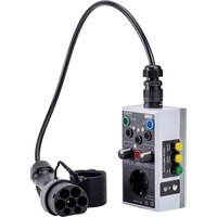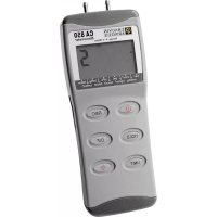
C.A 850 - Weather Station CHAUVIN ARNOUX - Free user manual and instructions
Find the device manual for free C.A 850 CHAUVIN ARNOUX in PDF.


| Technical Features | C.A 850 Weather Station with sensors for temperature, humidity, atmospheric pressure, and wind speed. |
|---|---|
| Usage | Ideal for individuals and professionals wishing to monitor local weather conditions. |
| Maintenance and Repair | Regularly check the sensors and replace batteries if necessary. |
| Safety | Use the device according to the manufacturer's instructions to avoid any risk of damage. |
| General Information | Compatible with various accessories for enhanced customization. Manufacturer's warranty included. |
Frequently Asked Questions - C.A 850 CHAUVIN ARNOUX
User questions about C.A 850 CHAUVIN ARNOUX
0 question about this device. Answer the ones you know or ask your own.
Ask a new question about this device
Download the instructions for your Weather Station in PDF format for free! Find your manual C.A 850 - CHAUVIN ARNOUX and take your electronic device back in hand. On this page are published all the documents necessary for the use of your device. C.A 850 by CHAUVIN ARNOUX.
USER MANUAL C.A 850 CHAUVIN ARNOUX
Thank you for purchasing this C.A 850 digital pressure gauge.
For best results from your instrument:
read these operating instructions carefully,
comply with the precautions for use.

WARNING, risk of DANGER! The operator must refer to these instructions whenever this danger symbol appears.

WARNING, risk of electric shock. The voltage applied to parts marked with this symbol may be hazardous.

Equipment protected by double insulation

Application or withdrawal authorized on conductors carrying dangerous voltages. Type B current sensor as per IEC 61010-2-032.

Battery.

The CE marking indicates conformity with European directives, in particular LVD and EMC.
The rubbish bin with a line through it indicates that, in the European Union, the product must undergo selective disposal in compliance with Directive WEEE 2002/96/EC.
CONTENTS
- PRESENTATION 10
-
PRECAUTIONS FOR USE 10
3.DESCRIPTION OF THE INSTRUMENT 11 -
OPERATION OF THE INSTRUMENT 12
4.1.《Monitoring》mode 12
4.2.《Differential measurement》mode 12
4.3. Adjustment of the zero 12
4.4. Calibration ad adjustment of the instrument 12
4.5.《Standby》mode 13
4.6. Errors: causes and action 13
- GENERAL SPECIFICATIONS 14
6.MAINTENANCE 14
6.1. Servicing 14
6.2. Cleaning the casing 14
6.3.Metrological check. 14
6.4. Repairs 14
- TO ORDER 15
Our guarantee is applicable, unless otherwise stated, for twelve months following the date of supply of the equipment (extract from our General Sales Conditions, available on request).
1. PRESENTATION
The CA 850 pressure gauge is ideal for measuring pressure levels in air-conditioning installations, medical equipment and pneumatic control systems.
It measures relative pressures - pressure measured in psi in relation to atmospheric pressure - and differential pressures - difference between two pressures.
11 measurement units are available for selection : bar, mmHg, ozin², kg/cm², inH₂O, kPa, ftH₂O, inHg, cmH₂O, mbar.
2. PRECAUTIONS FOR USE
The pressure gauge should only be used by people qualified to work on pressurized circuits. The manufacturer and its distributors disclaim any responsibility for damage resulting from improper unqualified use of the instrument. Refer to the general terms of sale.
The battery compartment must be closed before using the pressure gauge.
Ensure that no dust or foreign matter penetrates inside the pressure gauge.
To avoid damage due to overpressure, comply with the measuring range of the pressure gauge.
To prevent corrosion of the pressure sensor, the pressure gauge must not be used with corrosive gases.
- To prevent a sudden pressure drop in a pressurized circuit, close valves to isolate the portion of the circuit where the pressure gauge is to be mounted or removed and slowly release the pressure before attempting to open this portion of the circuit.
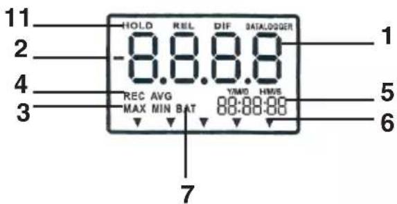
- Main screen indicating the pressure measurement in the unit selected
- “-” indicates a negative pressure
- maximum or minimum pressure recorded
- Indicates that the monitoring mode has started
- Secondary screen indicating the time since the start of monitoring mode
- Indicates the pressure unit selected
- Low battery indicator
- Indicates that differential pressure mode has been activated
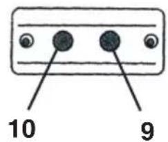
- Positive input
- Negative input
- Indicates that the value measured is frozen on the screen
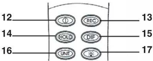
- Power button
- Monitoring mode trigger button
- Holding of the value measured
- Differential measurement mode access button
- Pressure unit selection button
- Back-lighting
Before going into this mode, select the unit of pressure, as you will not be able to change it once you are in monitoring mode.
When you press the button, a clock is started and "REC" is displayed on the screen.
This mode enables you to time/date-stamp the maximum and minimum values in your measuring operation. When you press the "REC" button a second time, MAX is displayed on the screen and the maximum value from the measuring operation is indicated on the main screen. The clock indicates the time when this event occurred during the measuring operation.
When you press a third time, you obtain the same information for the minimum value.
A fourth press returns you to the current value.
To exit from this mode, press the "REC" button for 3 seconds.
Note: The "differential measurement" mode is not accessible from the "monitoring" mode.
4.2. «DIFFERENTIAL MEASUREMENT» MODE
When you press the «DIF» button, you access the «differential measurement» mode.
The differential measurement mode measures the difference between two pressures. But it can also be used to quantify pressure variations (connect one input to your system and leave the other at atmospheric pressure).
Before going into this mode, select the unit of pressure, as you will not be able to change it once you are in monitoring mode.
When you press the button, the "DIF" symbol and the relative zero are displayed on the screen. From now on, only the pressure change will be indicated.
To exit from this mode, press the "DIF" button.
4.3. ADJUSTMENT OF THE ZERO
Leave the inputs at atmospheric pressure and press the «HOLD» button for 2 seconds. The screen switches off, indicates «0.0.0.0» from right to left and then the zero is displayed.
4.4. CALIBRATION AD ADJUSTMENT OF THE INSTRUMENT

Calibration can only be performed using a pressure calibrator.
First, set the zero
Then switch off the instrument
Press the "REC" and "power" buttons simultaneously. "CA" appears on the screen. You are now in setting mode.
Check that the unit selected is "psi" before starting to adjust the positive input.
■ By default, the CA 850 uses 80 psi as the calibration point. However, it can be set between 78 and 82 psi. If the calibration source is not at 80 psi, adjust the calibration point with the "DIF" button to increase and with the "back-lighting" button to reduce.
- Record the calibration point by pressing the "REC" button. "SA" appears on the screen after 2 seconds. The pressure gauge then switches automatically to adjustment of the negative pressure.
Follow the same calibration procedure for the negative pressure. - Record the calibration point again. After 2 seconds, "END" and "CA" appear on the screen and the pressure gauge then returns to the measurement mode.
If you cannot record the calibration point using the "REC" button, the "SA" symbol is not displayed; check that:
- the pressure calibration source is between 78 and 82 psi
- you have connected the correct input: positive or negative
If you want to go directly to calibration of the negative input, press the "UNIT" button.
4.5.《STANDBY》MODE
The instrument is switched off automatically after approximately 20 minutes without any activity. For long monitoring periods, you can deactivate the "standby" mode by pressing the "power" and "HOLD" buttons simultaneously when the instrument is switched off. An "n" is displayed on the screen: "standby" mode is deactivated. The next time you switch on the pressure gauge, the "standby" mode will be reactivated.
4.6. ERRORS: CAUSES AND ACTION
No display:
Check that the battery is connected correctly and that it's charge is sufficient.
If the screen display disappears, check that "standby" mode is not activated.
BAT display:
There may be measurement errors. Replace the battery.
Err. 1:
When the pressure is greater than the upper limit of the measurement range, "Err. 1" is displayed on the screen.
Err. 2 :
When the pressure is less than the lower limit of the measurement range, "Err. 2" appears on the screen.
Err.3:
When you are in "differential measurement mode", "Err. 3" is displayed if the differential pressure value is larger than the maximum display.
Err. 4 :
When you set the zero, make sure that no pressure is applied. Otherwise, "Err. 4" appears on the screen. If "Err. 4" appears on the screen even when no pressure is applied, it means that the sensor is damaged (see § 6 Repairs).
5. GENERAL SPECIFICATIONS
Measuring range: 0 to ± 100 psi
Maximum pressure : 150 psi
Resolution : 0.1 psi (see attachment 1 for the other measurement units)
Accuracy: ± 0.3 % full scale
Response time: 0.5 s
Display:4-digitLCDscreen
Climatic environment :
Use: Temperature: 0 to 50^ (32 to 122^ )
Storage: Temperature: -20 to 60^ (-4 to 140^ )
Power supply : One 9V battery
Dimension / weight : 72 x 182 x 30 mm / 220 g ( with battery)
6. MAINTENANCE
Only use specified spare parts for maintenance purposes. The manufacturer cannot accept any responsibility for accidents occurring following repairs carried out outside its after-sales department or approved maintenance network.
6.1. SERVICING
To replace the battery:
- Switch off the pressure gauge
- Remove the cover at the bottom of the instrument
- Replace the old battery with a 9V battery (6LR61 or 6LF22 type)
6.2. CLEANING THE CASING
Clean the unit with a cloth and a little soapy water.
Wipe off with a damp cloth.
Do not use any solvents.
6.3. METROLOGICAL CHECK
Like all measuring or testing devices, the instrument must be checked regularly.
This instrument should be checked at least once a year. For checking and calibration, contact one of our accredited metrology laboratories (information and contact details available on request), at our Chauvin
Arnoux subsidiary or the branch in your country
6.4. REPAIRS
For all repairs before or after expiry of warranty, please return the device to your distributor.
C.A850. P01184101
Supplied with a carrying case, 2 connection tubes (ID = 4mm and L = 500 mm), one 9V battery and this operating manual.
Our international contacts
www.chauvin-arnoux.com/contacts

CHAUVIN ARNOUX GROUP
CHAUVIN®
ARNoux
VIN ARNOUX GROUP