TK255MS - Saw Holzmann - Free user manual and instructions
Find the device manual for free TK255MS Holzmann in PDF.
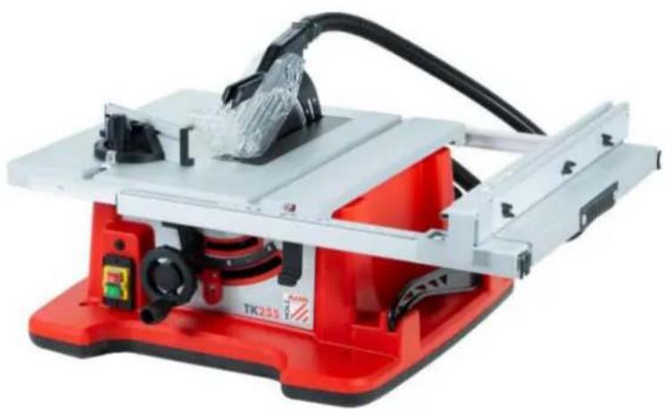
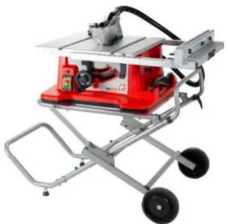
| Technical Features | Holzmann TK255MS table saw, powerful motor, cutting capacity of 255 mm, cutting depth of 85 mm. |
|---|---|
| Usage | Ideal for carpentry work, cutting wood, panels, and similar materials. |
| Maintenance and Repair | Regularly check the blade condition, lubricate moving parts, clean after each use. |
| Safety | Use safety glasses, gloves, and follow safety instructions during use. |
| General Information | Lightweight for easy handling, compact dimensions for easy storage. |
Frequently Asked Questions - TK255MS Holzmann
User questions about TK255MS Holzmann
0 question about this device. Answer the ones you know or ask your own.
Ask a new question about this device
Download the instructions for your Saw in PDF format for free! Find your manual TK255MS - Holzmann and take your electronic device back in hand. On this page are published all the documents necessary for the use of your device. TK255MS by Holzmann.
USER MANUAL TK255MS Holzmann
STOLNI KOTOUCOVÁ PILA
STOLOVÁ KOTUČOVÁ PILA
SEGA CIRCOLARE DA BANCO
TK255
Optional
Untergestell / stand / support / bastidor / Opce
Podstavec / Opcia
13.1 Intended Use of the Machine 28
13.1.1 Technical Restrictions 28
13.1.2 Prohibited Use / Forseeable Misuse 28
13.2User Requirements 28
13.3 Safety Devices 29
13.4 General Safety Instructions 29
13.5 Electrical Safety 29
13.6 Special Safety Instructions for that machine 30
13.7 HazardWarnings 30
14 TRANSPORT 31
15 ASSEMBLY 31
15.1 Checking scope of delivery 31
15.2 The workplace 31
15.3Assembling the machine 32
16 OPERATION 33
16.1 Initial check before start 33
16.2Operation 34
16.2.1 Adjusting cutting height / angle of saw blade 34
16.2.2 Adjusting the rip fence 34
16.2.3 Adjusting table extension 34
16.2.4 Adjusting angle/mitre stop 35
16.2.5 Switching machine ON/OFF 35
16.2.6 Existing storage places 35
16.3Operation modes 35
17 CLEANING, MAINTENANCE, STORAGE, DISPOSAL 36
17.1 Cleaning 36
17.2 Maintenance 36
17.2.1 Maintenance schedule 37
17.2.2 Setting for rip-fence 37
17.2.3 Table adjustment 38
17.2.4 Changing the saw balde 38
17.2.5 Check /exchange carbon brushes 39
17.2.6 Overload-protection 39
17.3 Storage 39
17.4 Disposal 39
18 TROUBLESHOOTING 39
19 PROLOGO (ES) 41
20 SEGURIDAD 42
20.1 Uso conforme a las specifications 42
EN READ THE MANUAL! Read the user and maintenance manual carefully and get familiar with the controls in order to use the machine correctly and to avoid injuries and machine defects.
EN Protective clothing!
EN Stop and pull out the power plug before any break and engine maintenance!
EN Warning about cut injuries!
FR Attention aux coupures!
CZ Vystraha prd reznymi poranenimi!
SK Vystraha pred reznymi poraneniami!
EN Protection class II!
EN Missing or non-readable security stickers have to be replaced immediately!
This manual contains information and important instructions for the installation and correct use of the tablesaw TK255, hereinafter referred to as "machine".
Following the usual commercial name of the device (see cover) is substituted in this manual with the name "machine".

This manual is part of the product and shall not be stored separately from the product. Save it for later reference and if you let other people use the product, add this instruction manual to the product.
Please read and obey the security instructions!
Due to constant advancements in product design, construction pictures and content may diverse slightly. However, if you discover any errors, inform us please.
Technical specifications are subject to changes!
Please check the product contents immediately after receipt for any eventual transport damage or missing parts.
Claims from transport damage or missing parts must be placed immediately after initial product receipt and unpacking before putting the product into operation.
Please understand that later claims cannot be accepted anymore.
Copyright
© 2018
This document is protected by international copyright law. Any unauthorized duplication, translation or use of pictures, illustrations or text of this manual will be pursued by law.
Court of jurisdiction is the regional court Linz or the competent court for 4170 Haslach, Austria!
Customer service contact
This section contains information and important notes on safe commissioning and handling of the machine.

For your personal safety, please read these operating instructions carefully before commissioning. This will enable you to handle the machine safely and prevent misunderstandings as well as personal injury and damage to property. Also observe the symbols and pictograms used on the machine as well as the safety and danger information!
13.1 Intended Use of the Machine
The machine is intended exclusively for the following activities:
Cutting (longitudinal and cross cuts) of wood and materials with similar properties to wood within the specified technical limits.
HOLZMANN MASCHINEN assumes no responsibility or warranty for any other use or use beyond this and for any resulting damage to property or injuries.
13.1.1 Technical Restrictions
The machine is intended for use under the following ambient conditions:
Rel. Humidity: max. 65%
Temperature (operational) +5^ bis +40^
Temperature (Sterne, Temperature) -20°C bis +55°C
13.1.2 Prohibited Use / Forseeable Misuse
- Operation of the machine without adequate physical and mental aptitude
- Operating the machine without knowledge of the operating instructions
- Changes in the design of the machine
- Operating the machine in a potentially explosive environment (machine can generate ignition sparks during operation)
- Operation of the machine in closed rooms without chip and dust extraction (a normal household vacuum cleaner is not suitable as an extraction device).
- Operating the machine outside the limits specified in this manual
- Remove the safety markings attached to the machine.
- Modify, circumvent or disable the safety devices of the machine.
- Cutting of materials with dimensions outside the limits specified in this manual
- Use of tools which do not meet the safety requirements of the standard for machine tools for woodworking (EN847-1).
- Use of saw blades made of HSS steel.
- Use of saw blades with a lower permitted speed than the machine
The improper use or disregard of the versions and instructions described in this manual will result in the voiding of all warranty and compensation claims against Holzmann Maschinen GmbH.
13.2 User Requirements
The physical and mental suitability as well as knowledge and understanding of the operating instructions are prerequisites for operating the machine. Persons who, because of their physical, sensory or mental abilities or their inexperience or ignorance, are unable to operate the machinery safely must not use it without the supervision or instruction by a responsible person.
Please note that local laws and regulations may stipulate the minimum age of the operator and restrict the use of this machine!
Put on your personal protective equipment before working on the machine.
Work on electrical components or equipment may only be carried out by a qualified electrician or under the instruction and supervision of a qualified electrician.
13.3 Safety Devices
The machine is equipped with the following safety devices:
| ·protective device Saw blade protection | |
| ·Push stick |
13.4 General Safety Instructions
To avoid malfunctions, damage and health hazards when working with the machine, in addition to the general rules for safe working, the following points must be observed:
-
Before commissioning, check the machine for completeness and function.
-
Choose a level, vibration-free, non-slip surface for the installation location.
-
Ensure sufficient space around the machine!
-
Ensure sufficient lighting conditions at the workplace to avoid stroboscopic effects!
-
Only use perfect tools that are free of cracks and other defects (e.g. deformations).
-
Remove setting tools from the machine before switching on.
-
Keep the area around the machine free of obstacles (e.g. dust, chips, cut workpiece parts etc.).
-
Check the strength of the machine connections before each use.
-
Never leave the running machine unattended. If necessary, stop the machine before leaving.
-
The machine may only be operated, serviced or repaired by persons who are fami and who have been informed of the dangers arising in the course of this work.
-
Ensure that unauthorised persons maintain an appropriate safety distance from the machine and, in particular, keep children away from the machine..
-
Wear suitable protective equipment (eye protection, dust mask, respiratory protection, ear protection, gloves when handling tools) as well as close-fitting work protective clothing - never wear loose clothing, ties, jewellery, etc. - danger of being drawn in!
Work with gloves on rotating parts is not permitted!
-
Hide long hair under hair protection.
-
Do not remove any sections or other parts of the workpiece from the cutting area while the machine is running!
-
Do not remove splinters and chips by hand! Use a sliding stick for this purpose!
Always work with care and the necessary caution and never use excessive force.
-
Do not overload the machine!
-
Do not work on the machine if you are tired, not concentrated or under the influence of medication, alcohol or drugs!
-
Do not use the machine in areas where vapours from paints, solvents or flammable liquids represent a potential danger (danger of fire or explosion!).
-
Do not smoke in the immediate vicinity of the machine (fire hazard)!
-
Do not use the machine if it cannot be switched on and off with the ON/OFF switch.
-
Make sure that the device is earthed.
-
Only use suitable extension cords.
-
Always shut down the machine before carrying out any conversion, adjustment, measuring, cleaning, maintenance or repair work and always disconnect it from the power supply for maintenance or repair work. Before starting any work on the machine, wait until all tools or machine parts have come to a complete standstill and secure the machine against unintentional restarting.
13.5 Electrical Safety
- Only use suitable extension cords. (cross-section 1.5mm^2 for length up to 25m; H05VV-F)
- A damaged or tangled cable increases the risk of electric shock. Handle the cable with care. Never use the cable to carry, pull or disconnect the power tool. Keep the cable away from heat, oil, sharp edges or moving parts.
-
Proper plugs and sockets reduce the risk of electric shock.
Water entry into machine increases the risk of electric shock. Do not expose machine to rain or moisture. -
The machine may only be used in humid environments if the power source is protected by a residual current circuit breaker.
- Do not use the power tool if it cannot be turned on and off with the ON/OFF switch.
- Avoid contact of the body with grounded surfaces such as pipes, radiators, ovens and refrigerators. There is an increased risk of electric shock if the body is earthed.
13.6 Special Safety Instructions for that machine
- During operation of the machine wood dust is generated. Therefore, connect the machine to a suitable dust collection system for dust and chips during installation!
- Always switch on the dust collection system before you start machining the workpiece!
- Never remove sections or other parts of the workpiece from the cutting area while the machine is running.
- When using milling tools with a diameter of ≥ 16 mm and circular saw blades, these must comply with EN 847-1:2013 and EN 847-2:2013; tool carriers must comply with EN 847-3:2013;
- Replace cracked and deformed saw blades immediately, they cannot be repaired.
- Use clean and sharpened saw blades, which are less sensitive to malfunctions and easier to guide.
- Cut only one workpiece at the same time.
- For a workpiece that is wider or longer than the supporting table, sufficient support such as table extensions, saw blocks, etc. must be provided.
- Allow the saw blade to reach full speed before touching the workpiece.
- If the workpiece or saw blades become jammed, turn off the machine immediately. Wait until all moving parts have come to a standstill and disconnect the plug from the power source, then start removing the jammed material.
- The stops or other machine parts must not touch the saw blade at any time.
- Hold the workpiece securely with both hands and press it firmly onto the saw table.
- Do not use the machines for slitting.
- Protect the saw blade from impact and shock and do not subject the saw blade to lateral pressure.
- The riving knife must be aligned with the saw blade to avoid jamming the workpiece.
- Only cut straight workpieces so that they can rest against the rip fence.
- Keep the push stick on the machine.
- Never stand in direct line with the saw blade.
- Keep the protective covers fitted and check that they are correctly fitted and not damaged and repair or replace them if they are not.
- Always use the saw blade guard and riving knife for cut-offs.
- After completing work steps such as grooving, rebating, etc., immediately attach the protective cover removed for this purpose.
- Do not put fingers or hands near the saw blade or in the sawing area.
- Only guide the workpiece towards the saw blade against the direction of saw blade rotation.
- Never use the angle/mitre fence to feed the workpiece when cutting lengthways, and never use the rip fence in addition to the angle/mitre fence to feed the workpiece when cutting cross-sections (danger of jamming)
- Use a push stick if the distance between the fence (parallel, fence bar) and the saw blade is less than 150mm , and a sliding block if it is less than 50mm .
- Never use a damaged push stick.
Always use the rip fence or angle/mitre fence. Do not work "freehand". - Never reach around or over a rotating saw blade.
13.7 HazardWarnings
Despite their intended use, certain residual risks remain. Due to the structure and construction of the machine, hazardous situations may occur when handling the machines:
- Touching the saw blade in the uncovered sawing area.
- Injuries caused by touching the running saw blade
- Kickback of workpieces and workpiece parts due to insufficient fastening
- Saw blade breakage or throwing out parts of the saw blade
- Hearing loss / damage to health due to wood dust if protective equipment and dust collection systems are not used in closed rooms
Or others that are marked as follows in this manual:
DANGER

A safety instruction designed in this way indicates an imminently hazardous situation which, if not avoided, will result in death or serious injury.
WARNING

Such a safety instruction indicates a potentially hazardous situation which, if not avoided, may result in serious injury or even death..
CAUTION

A safety instruction designed in this way indicates a potentially hazardous situation which, if not avoided, may result in minor or moderate injury.
NOTICE

A safety notice designed in this way indicates a potentially hazardous situation which, if not avoided, may result in property damage.
Irrespective of all safety regulations, their sound common sense and corresponding technical suitability/training are and remain the most important safety factor in the error-free operation of the machine. Safe working depends first and foremost on you!
14 TRANSPORT
For proper transport, follow the instructions and information on the transport packaging regarding centre of gravity, attachment points, weight, means of transport to be used and prescribed transport position, etc.
Transport the machine in its packaging to the place of installation. When lifting, carrying and depositing the load, make sure that you are in the correct posture:
- Lifting, Depositing
Ensure stability when lifting / setting down (legs hip width).
Lift / lower load with bent knees and straight back (like weightlifter).
Do not lift / lower the load jerkily.
- Carrying
Carry load with both hands as close to body as possible.
Carry load with straight back.
NOTICE

Transport of the unpacked machine only in transport position = saw unit in the lower position and locked by means of bolt as well as drag lock locked. Lifting the machine only by the transport handles.
15 ASSEMBLY
15.1 Checking scope of delivery
Check the machine immediately after delivery for transport damage and missing parts.
15.2 The workplace
Choose a suitable place for the machine.
Pay attention to the safety requirements and the dimensions of the machine.
The selected location must ensure a suitable connection to the electrical supply as well as the possibility of connection to an extraction system. Ensure that the selected workplace (machine stand, worktop, ...) can bear the load of the machine and that the machine can be attached to it using screws (screws are not included in the scope of delivery). The machine must be levelled at all support points at the same time. In addition, a distance of at least 0.8m around the machine must be secured all around. The necessary space for feeding long workpieces must be provided.
Assembly on HOLZMANN machine stand TK255MS (optional accessory)
Fix the machine to the machine table with 4 screws / washers / nuts.
15.3 Assembling the machine
The machine comes pre-assembled. The following minor assembly / adjustment must still be carried out before use and the connection to the power supply / dust collection system must be made as well as setting up the machine in a suitable working location and adjusting the attachments according to the following steps:

2
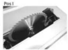
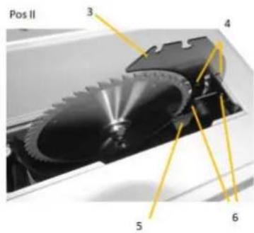
Adjusting riving knife:
The riving knife can be locked in 2 positions (Pos I, Pos II). 1. 1. in the lower position (for grooving / rebating) the two lower bolts are engaged (ATTENTION Here suitable protective equipment (e.g. pressure comb,) is necessary to ensure safe working.
-
in the upper position = working position the upper two ones. Working steps for changing the position:
-
Remove the table insert, loosen the screw for this and remove the table insert.
-
Move the saw blade to the highest possible position.
-
Loosen lever (5)
-
Pull the riving knife up (upper position) or push it down (lower position). Make sure that the appropriate bolts engage in the holes of the riving knife and then clamp the lever again.
Check in the upper position (= working position) whether the gap between the riving knife and the saw blade is within the specified limits.
The radial gap between the saw blade and the riving knife must be a maximum of 3 - 8mm
-
The thickness of the riving knife must be less than the cutting width and greater than the log thickness.
-
The riving knife must always be in line with the saw blade.
-
For normal rip cuts, the riving knife must always be in the highest possible position.
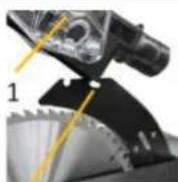
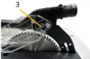
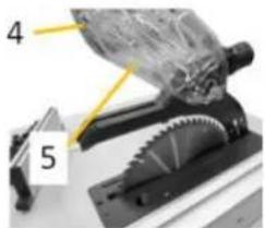
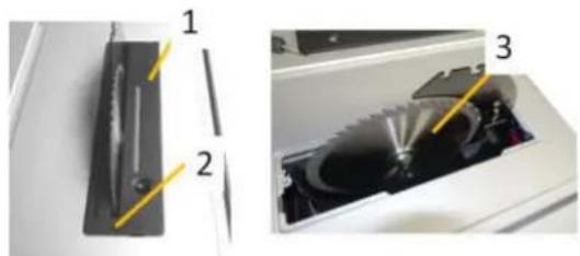
Assembly saw blade protection cover:
Only install the protective cover when the
the riving knife is in the working position (Pos II)
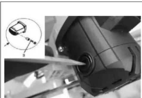
- Insert the protective cover (1) with the rear guide bar into the recess (2) on the riving knife and push it backwards.
- Press the bolt (3) on the protective cover and fold it down (parallel to the saw table surface).
- The bolt must engage and the protective cover must sit firmly and securely.
Before each use, check that the two moving parts of the protective cover (4 and 5) can move properly. Do not use the machine if the protective cover does not move freely and does not close immediately.
| 1 2 3 4 5+6 | Assembly rip-fence The rip fence can be mounted to the left and right of the saw blade. - Release the locking lever (3) on the rip fence and insert the rip fence into the rear guide on the saw table as shown. - Fold the rip fence down and hook it into the front guide on the saw table. - The rip fence can be moved freely in its position when the locking lever is unlocked. - To fix it, press the locking lever down (ripe fence fixed). The stop bar (4) is used for cutting narrow workpieces and for cutting mitre angles and can be mounted to the left or right of the rip fence. To mount the stop rail (4), insert the 3 screws (S) into the holes on the rip fence (the hexagonal head of the screw must be positioned on the side where the stop bar is located). Put on the washer and the wing nut (5+6) but do not tighten them yet. Thread the guide profile of the stop rail over the hexagonal heads and then fix it with the wing nut. |
| 1 2 3 4 | Assembly mitre gauge Insert the rail of the angle/mitre fence (1) into the guide groove on the table (2). The angle/mitre fence can be mounted to the left/right of the saw blade. |
| 1 2 3 4 | Assembly dust hose • Connect the extraction hose (1) to the saw blade guard (3) and to the dust collection connection adapter (2) on the back of the machine. |
| 1 | Connection to dust collection system Connect your dust collection system to the appropriate extraction hose by plugging it over the dust collection adapter (1).. |
16 OPERATION
16.1 Initial check before start
- Check that the speed of the machine is lower than the max. permissible speed of the saw blade used.
- Check saw blade rotation and saw blade dimensions to match the machine.
- Check that the saw blade guard works properly.
- Check whether the connection to a dust collection system is installed.
- Check whether the stops/fences are set correctly and the saw blade is tightened.
-
Check whether the machine is fixed on the working plate or a machine stand.
-
Check whether the saw blade can run freely.
16.2 Operation
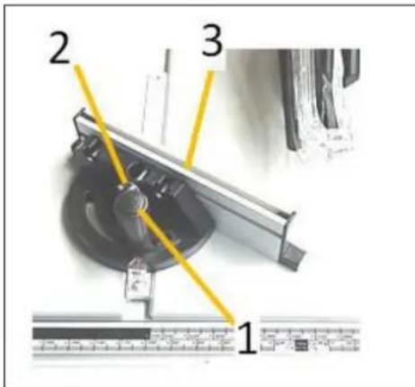
16.2.1 Adjusting cutting height / angle of saw blade
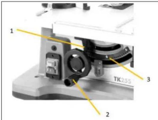
Adjusting cutting height:
- The cutting height is adjusted by turning the handwheel (2). o counterclockwise: saw blade is set upwards o clockwise: saw blade is set downwards
Adjusting cutting angle
- Loosen the angle adjustment lock (1).
- Adjust the saw blade to the desired angle
Fix the angle adjustment lock (1) again.
16.2.2 Adjusting the rip fence
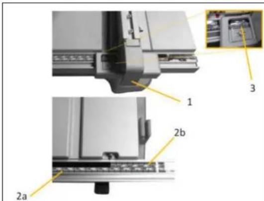
Release the locking lever (1) on the rip fence by folding it up.
Move the rip fence until the desired distance to the saw blade is achieved.
(read off the scale (3)) and then fix the locking lever. Info about the scale:
The lower marking (2a) applies when the table extension is not in use.
The upper scale (2b) applies when the table extension is in use.
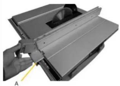

NOTICE
To ensure exact positioning and avoid jamming / misalignment, press the stop A against the guide when moving it.
16.2.3 Adjusting table extension
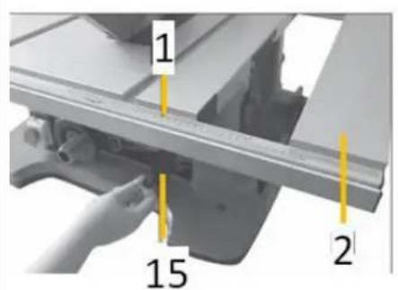
- The table extension (2) is used for wide workpieces.
- Release the table extension lock (15) and bring the table extension (2) into the desired position with the rails (1). At the desired position, fix the table in position again with the table extension lock (1).
16.2.4 Adjusting angle/mitre stop
- Release the angle stop lock (2).
- Set the desired angle
- Lock the angle stop (2) again.
- The position of the fence can be adjusted by loosening the screw (2) and sliding it.
- ATTENTION: Check the distance to the saw blade and readjust if necessary.
16.2.5 Switching machine ON/OFF

Switch the machine ON:
Press the ON button (I)
Switch the machine OFF:
Press the ON-OFF switch (0)
16.2.6 Existing storage places
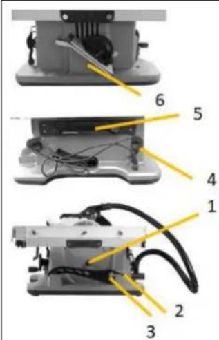
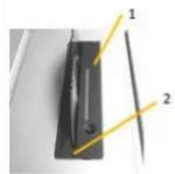
- A spare saw blade is stored with the spare saw blade attachment (1).
The rip fence is stored in slot 2 - The push stick is stored in slot 3.
- The power cord is stored in the power cord holder (4).
- The tool is stored in the tool compartment
- The angle stop is stored in the slot (5)
16.3 Operation modes
Sawing straight cuts
- Position the rip fence to the desired cutting width.
- Place the workpiece on the saw table in front of the saw blade cover.
- Adjust the saw blade height so that the upper teeth are approx. 3-6 mm above the workpiece.
- Switch on the machine
- Saw through the workpiece at a steady feed rate. If you apply too much pressure, the saw blade tips may overheat and the workpiece may be damaged.
- Switch off the machine when you have finished sawing and wait until the saw blade has come to a complete stop..
Sawing vertical metre angles
- Set the desired vertical litre angle of the saw blade.
The saw blade is tilted to the left here to avoid possible contact with the saw blade, the rip fence must be to the right of the saw blade or, if it is mounted on the left, the stop bar must be attached to the rip fence on the right and the distance to the saw blade must be checked.
- Adjust the rip fence to the desired cutting width.
- Place the workpiece on the saw table in front of the saw blade cover.
- Adjust the saw blade height so that the upper teeth are approx. 3-6 mm above the workpiece.
- Switch on the machine
- Saw through the workpiece at a steady feed rate.
- If you apply too much pressure, the saw blade tips may overheat and the workpiece may be damaged.
- Switch off the machine when you have finished sawing and wait until the saw blade has come to a complete stop
Sawing horizontal litre angels
- Set the desired litre angle on the litre/angle fence.
- Place the workpiece against the angle stop.
- Set the saw blade height so that the upper teeth are approx. 3-6 mm above the workpiece.
- Switch on the machine
- Press the workpiece against the angle stop with one hand and slowly push it forward in the guide groove with the other hand.
- After the sawing process is finished, switch off the machine and wait until the saw blade has come to a complete stop.
17 CLEANING, MAINTENANCE, STORAGE, DISPOSAL
WARNING
Danger due to electrical voltage! Handling at the machine with upright power supply can lead to serious injuries or death. Always disconnect the machine from the power supply before cleaning, servicing or maintenance work and secure it against unintentional reconnection!
17.1 Cleaning
NOTE

Wrong cleaning agents can attack the varnish of the machine. Do not use solvents, nitro thinners, or other cleaning agents that could damage the machine's paint. Observe the information and instructions of the cleaning agent manufacturer!
Regular cleaning is a prerequisite for the safe operation of the machine and its long service life.
- Therefore, clean the machine after each use and remove any sawdust with a brush, broom or vacuum cleaner.
17.2 Maintenance
The machine is low-maintenance and only a few parts have to be serviced. Nevertheless, malfunctions or defects which could impair the safety of the user must be rectified immediately!
Before each operation, check that the safety devices are in perfect condition.
Regularly check that the warning and safety labels on the machine are in perfect and legible condition.
- Use only proper and suitable tools.
- Only use original spare parts recommended by the manufacturer.
17.2.1 Maintenance schedule
The type and degree of machine wear depend on the operating conditions. The following intervals apply when the machine is used within the specified limits:
| interval | components | activity |
| Before usage | Saw blade | Check for damage and replace if necessary. |
| Saw blade guard | Check function (see function check saw blade protection) | |
| Table inlet | Check for damage and replace if necessary. | |
| Cable | Check for damage and repair if necessary. | |
| After usage | Maschine | Remove dust/wood splinters and dirt |
| Saw blade guard | ||
| after 50h (/10h) | Carbon brush | Check and replace if necessary. |
| When required | Saw balde | Check sharpness of saw blade and replace when necessary |
17.2.2 Setting for rip-fence
| 1 1 | Adjusting clamping force The clamping force and thus the sideways movement can be adjusted by means of the screw (1).. |
| NOTICE A screw that is too tight can lead to component failure, while a spring that is too weak can cause the set position isn't hold in place during operation. Optimum clamping force is given when the fixing lever (2) can still be pressed down slightly and the stop is still in position. | |
| Set parallelism of rip fence The alignment of the rip fence to the saw blade can be adjusted by means of the two screws (1). For an optimal parallel adjustment. Loosen the two screws (1), position the rip fence towards the saw blade, then fix it in position with the fixing lever and fix the two screws (1) again. | |
| Setting the display scale of the rip fence The indicator scales (1 and 3) can be moved in their position to set the exact distance to the saw blade, loosen the screw (1 or 2) and adjust to the exact value of the current distance, then fix the screw again and check by means of a measuring tape or cut. |
17.2.3 Table adjustment
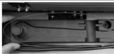
1.remove tool box
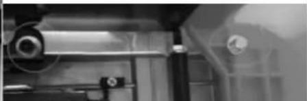
- Loosen the following srews (see pictures)
-
adjust the work table. Grooves must be parallel to the saw blade
-
tighten screws again
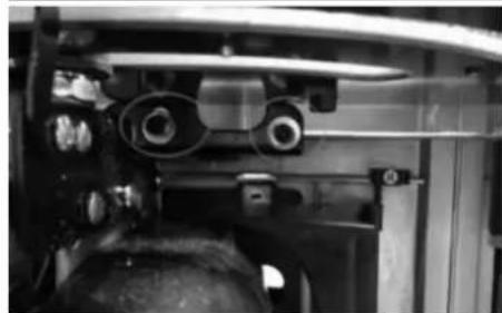
17.2.4 Changing the saw balde
CAUTION

Risk of injury! Wear protective gloves when changing the saw blade.
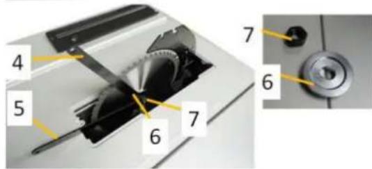
- Remove the saw blade protection cover from the riving knife.
- Remove the table insert (1)
- Position the saw blade (3) in its uppermost position.
- Attach the two ring spanners (4 + 5) to the nut (7) and flange (6) respectively.
- Loosen the nut (7) (LINGGGEWINDE) and remove it and the flange (6).
- Remove the saw blade (3)
- Clean the arbor, screw and flange if necessary.
Install the new saw blade
CAUTION

Observe the correct direction of rotation and dimension of the saw blade:
Saw blade 254 mm and max. thickness of 2.8-3.2mm, as well as mounting diameter of 30 mm.
- Fit the flange and secure the saw blade with the nut.
- Refit the table insert and the saw blade protection cover.
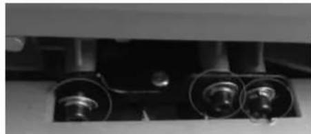
17.2.5 Check /exchange carbon brushes
Check the carbon brushes after the first 50 hours of operation with a new machine or when new brushes are fitted. After carrying out the first check, repeat the check every 10 hours of operation. If the carbon is worn to a length of 6mm or if the spring or contact wire is burnt or damaged, it is necessary to replace both brushes. If it turns out that the brushes are usable after removal, it is possible to refit them. When servicing the carbon brushes, open the two latches counterclockwise. Then remove the carbon brushes. Replace the carbon brushes in reverse order.
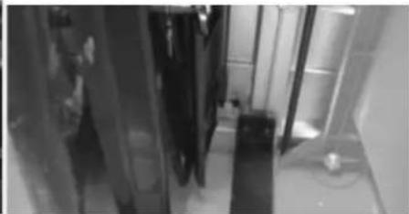
17.2.6 Overload-protection
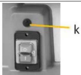
- Disconnect the machine from the power supply
- Allow the machine to cool down
- Check the machine for possible damage.
- Any damage must be repaired before switching on again!
- Reconnect the machine to the power supply
- Press overload switch (k)
17.3 Storage
NOTE

Improper storage can damage and destroy important components. Only store packed or unpacked parts under the intended ambient conditions!
When not in use, store the machine in a dry, frost-proof and lockable place to prevent the formation of rust on the one hand and to ensure that unauthorised persons and in particular children have no access to the machine.
17.4 Disposal
Observe the national waste disposal regulations. Never dispose of the machine, machine components or operating materials (like oil,...) in residual waste. If necessary, contact your local authorities for information on the disposal options available.
If you buy a new machine or an equivalent device from your specialist dealer, he is obliged in certain countries to dispose of your old machine properly.
18 TROUBLESHOOTING
WARNING
Danger due to electrical voltage! Manipulating the machine with the power supply up can lead to serious injuries or death. Always disconnect the machine from the power supply before carrying out any troubleshooting work!
Many possible sources of error can be excluded in advance if the machine is properly connected to the mains.
If you are unable to carry out necessary repairs properly and/or do not have the required training, always consult a specialist to correct/solve the problem!.
| Fault | Possible cause | correction |
| Motor does not run | (Extension) cable defective or too long. | Unplug, check with another machine. Check minimum cross-section! |
| Power supply (voltage, frequency). | Match power supply to requirements from Technical Data | |
| Motor defect | Replace or ask for service | |
| ON-OFF switch defective | Repair/replace switch | |
| Carbon brushes defective | Replace carbon brushes | |
| Overload protection activated | see chapter Overload protection | |
| Saw blade gets stuck | Incorrectly adjusted riving knife Not suitable saw blade | Adjust riving knife Distance 3-8 mm to circular saw blade |
| Blunt saw blade | Use a circular saw blade recommended for your material | |
| Material too hard or cutting too fast. | Replace sawblade | |
| Adjust cutting speed to workpiece hardness & motor power! | ||
| Material kickback | Blunt saw blade | Replace saw blade |
| Saw blade incorrectly assembled | Check and correct | |
| Cutting angle isn't correct / metre angle isn't correct | Incorrectly adjusted rip fence Incorrectly adjusted metre fence | adjust |
| Poor cutting results | Wrong saw blade Incorrect cutting speed | Change saw blade Adjust cutting speed |
19 PROLOGO (ES)
iEstimado cliente!!
Cher client, chere cliente,
27.1.1 Restrictions techniques
Temperature (stockage, transport)
-20°C à +55 °C
27.1.2 Applications interdites / Mauvaises applications dangereuses
(EN) With original HOLZMANN spare parts you use parts that are attuned to each other shorten the installation time and elongate your products lifespan.
IMPORTANT
The installation of other than original spare parts voids the warranty!
So you always have to use original spare parts
When you place a spare parts order please use the service formula you can find in the last chapter of this manual. Always take a note of the machine type, spare parts number and part name. We recommend to copy the spare parts diagram and mark the spare part you need. Or use the electronic ordering opportunity via the spare parts catalogue or spare parts request form on our homepage
You find the order address in the preface of this operation manual.
| No | name | Qty | No | name | Qty | No | name | Qty |
| 1 | ST3.5X16 cross recessed pan headtapping | 4 | 78 | fasten location block | 1 | 160 | fence cover | 1 |
| 2 | overload switch | 1 | 79 | saw blade guard2 | 1 | 161 | spring1 | 1 |
| 3 | ST3.9x10 cross recessed pan headtapping | 5 | 80 | ST3.9x12 cross recessed pan head tapping screw | 5 | 162 | fence fasten block2 | 1 |
| 4 | inductance | 1 | 81 | cover block | 1 | 163 | spring3 | 1 |
| 5 | capacitance | 1 | 82 | M14 hex nut | 1 | 164 | control screw | 1 |
| 6 | switch box | 1 | 83 | outer pressure board | 1 | 165 | triangle block | 1 |
| 7 | switch (KJD12) | 1 | 84 | saw blade | 1 | 166 | table insert | 1 |
| 8 | ST3.9X14 cross recessed pan head tapping | 2 | 86 | push sticker | 1 | 169 | extension bar cover | 2 |
| 9 | label for body | 1 | 87 | saw balde location ring | 1 | 171 | M6x12 bolt | 4 |
| 10 | M6 locking nut | 2 | 88 | inner pressure board | 1 | 172 | location block | 2 |
| 11 | big hand wheel | 1 | 89 | M5x12 cross recessed counter suck screw | 3 | 173 | M6screw | 16 |
| 12 | a6 big flat washer | 18 | 90 | bearing housing | 1 | 175 | extension bar1 | 1 |
| 13 | small handle | 1 | 91 | 6003 bearing | 1 | 181 | side plate guard | 3 |
| 14 | a 8 flat washer | 4 | 94 | a35 snap spring | 1 | 182 | M5x10 cross recessed pan head tapping screw | 6 |
| 15 | M6 stepped screw | 1 | 95 | output axis | 1 | 183 | work table | 1 |
| 16 | angle location | 2 | 96 | flat key5x5x12 | 1 | 185 | extension bar2 | 1 |
| 17 | M5x14 cross recessed big pan head screw | 2 | 97 | big gear wheel | 1 | 186 | work table scale | 1 |
| 18 | gear rack | 1 | 98 | a16 shaft circlip | 1 | 187 | extension bar1 cover | 2 |
| 19 | M4x12 cross recessed pan head screw | 3 | 99 | HK1210neddle baring | 1 | 188 | strength board for body | 1 |
| 20 | M4x8cross recessed pan head screw | 18 | 100 | Middle cover | 1 | 189 | M6x16 square neck screw | 4 |
| 21 | pointer of body | 1 | 101 | M8 lock nut | 1 | 190 | long pressure board | 2 |
| 22 | a4spring | 5 | 102 | a4 teech washer | 3 | 191 | weldment of extension board in work table | 1 |
| 23 | M4 hex nut | 2 | 103 | 6202 bearing | 1 | 192 | adjusting bar3 | 1 |
| 24 | M4X8 cross recessed countersuck screw | 5 | 104 | screw bar | 1 | 193 | extension fasten piece | 2 |
| 25 | rubber foot | 4 | 105 | rotor | 1 | 194 | a6 inner jump ring | 2 |
| 26 | machine body | 1 | 106 | 629bearing | 1 | 195 | spring2 | 2 |
| 27 | ST3.5X 10 cross recessed pan head tapping | 4 | 107 | ST4.8x60cross recessed pan head screw | 2 | 196 | M8 nut(left) | 1 |
| 28 | coiling hook (left) | 1 | 108 | stator | 1 | 197 | hexagon control screw | 1 |
| 29 | tooling box | 1 | 109 | fan shroud | 1 | 198 | M8 nut | 1 |
| 30 | sleeve | 1 | 110 | motor housing | 1 | 199 | adjusting bar1 | 1 |
| 31 | knob for tooling box | 1 | 111 | brush holder | 2 | 200 | adjusting bar2 | 1 |
| 32 | φ30X8X3 flat washer | 1 | 112 | carbon brush | 2 | 201 | a3x12 net | 2 |
| 33 | coiling hook(right) | 1 | 113 | brush holder cover | 2 | 202 | fasten block | 2 |
| 34 | M5 locking screw | 1 | 114 | (motor)connecting cable | 1 | 203 | a4.5x19 pin | 2 |
| 35 | M6x30 cross recessed pan head screw | 4 | 115 | cable plug | 1 | 204 | extension fasten block2 | 1 |
| 36 | M6x22 cross recessed pan head screw | 1 | 116 | cable | 1 | 205 | extension fasten block 1 | 1 |
| 37 | saw blade location block | 1 | 117 | M5x30 cross recessed pan head screw | 3 | 206 | a12 shaft jump ring | 2 |
| 38 | washer for blade guard | 2 | 118 | a5 spring washer | 4 | 207 | fasten bar | 1 |
| 39 | M6 star nut | 1 | 119 | a5 flat washer | 6 | 208 | a20x15x0 5washer | 4 |
| 40 | big torsion | 1 | 120 | ST3.9x10 cross recessed counter suck screw | 3 | 209 | fasten wrench | 1 |
| 41 | a3x25pin | 1 | 121 | angular scale cover | 1 | 210 | M5x12 bolt | 1 |
| 42 | rotate axis | 1 | 122 | angle board | 1 | 211 | active plate | 1 |
| 43 | M4 stepping screw | 1 | 123 | plastic washer | 1 | 212 | rotation axis pressure board | 2 |
| 44 | pressure handle | 1 | 124 | M6x18 knob | 1 | 213 | torsional spring | 2 |
| 45 | location ring | 1 | 125 | a4 spring | 1 | 214 | rotation axis | 1 |
| 46 | a10xa26x1 5plastic washer | 1 | 126 | pointer of angle scale | 1 | 215 | M5x8 cross recessed pan head screw | 7 |
| 47 | M6x40 cross recessed counter suck screw | 1 | 127 | alloy | 1 | 216 | tension disc | 1 |
| 48 | axle sleeve (1) | 1 | 128 | washer for alloy | 1 | 217 | 22 wrench | 1 |
| 49 | location block | 1 | 129 | M5x10 cross recessed counter suck screw | 1 | 218 | 5key | 1 |
| 50 | axle sleeve (2) | 1 | 131 | a 6 flat washer | 4 | 219 | 22 spanner | 1 |
| 51 | fasten bar | 1 | 134 | rving knife | 1 | 220 | base cover | 1 |
| 52 | M5x10 cross recessed pan head screw | 10 | 135 | rving knife pressure board(1) | 1 | 221 | ST4.8x20 cross recessed pan head tapping screw | 10 |
| 53 | gear | 2 | 136 | rving knife pressure board(2) | 1 | 222 | M6X40 oval head square neck bolt | 1 |
| 54 | M4x20 cross recessed counter suck screw | 2 | 137 | clamp screw | 1 | 223 | fence cover(1) | 2 |
| 55 | pointer seat | 1 | 138 | a 3x15 pin | 1 | 224 | fence for gauge | 1 |
| 56 | M4x6 cross recessed pan head screw | 3 | 139 | rving knife knob+cover | 1 | 225 | fasten nut | 1 |
| 57 | rotate support(1) | 1 | 140 | lock handle | 1 | 226 | M5X8 hex screw | 2 |
| 58 | M5x10 cross recessed counter suck screw | 4 | 141 | a5x38 pin | 2 | 227 | T-adapter | 1 |
| 59 | rotate bar(1) | 1 | 142 | small connecting rod | 1 | 228 | Hose (1.5) | 1 |
| 60 | rotate location block | 2 | 143 | connecting rod1 | 1 | 229 | active baffle plate | 1 |
| 61 | a5 big flat screw | 18 | 144 | a5x11 pin | 1 | 230 | torsional spring 2 | 2 |
| 62 | M6x16 inner hex screw | 6 | 145 | fence lock block1 | 1 | 231 | φ3X331 pin | 1 |
| 63 | a6spring | 8 | 146 | a5x28 pin | 1 | 232 | fixing baffle plate | 1 |
| 64 | 5x12cross recessed pan head screw | 2 | 147 | a5x30 pin | 1 | 233 | φ5X15X3 plain washer | 1 |
| 65 | motor support board | 1 | 148 | fence fasten piece | 2 | 234 | torsional spring 3 | 1 |
| 66 | output guard | 1 | 149 | fence movable seat | 1 | 235 | M5X14 cross pan head | 1 |
| 67 | M5x6 cross recessed pan head screw | 8 | 150 | pointer | 1 | 236 | ST3.9x16 crossing pan head tapping screw | 7 |
| 68 | saw blade guard1 | 1 | 151 | M3 stepping screw | 2 | 237 | fixed seat of blade cover left | 1 |
| 69 | M6x20 hex screw | 6 | 152 | fence lock block3 | 1 | 238 | fixed seat of blade cover right | 1 |
| 70 | pressure block | 2 | 153 | M6 butterfly plastic nut | 3 | 239 | M5 step screw | 4 |
| 71 | washer | 2 | 154 | a6 teeth washer | 2 | 240 | blade cover left | 1 |
| 72 | rotate support (2) | 1 | 155 | M6x50 bolt | 3 | 241 | blade cover right | 1 |
| 73 | rotate bar(2) | 1 | 156 | auxiliary fence | 1 | 242 | fix pin for blade cover | 1 |
| 74 | rotate location board | 1 | 157 | sliding bar of fence | 1 | 243 | spring for blade cover | 2 |
| 75 | M6x12 hex screw | 4 | 158 | fence | 1 | 244 | small pressure spring | 1 |
| 76 | M10 locking nut | 2 | 159 | a5x40 pin | 1 | 245 | φ6X12X0.5 plain washer | 4 |
| 77 | a10 flat washer | 3 |
56 EU-KONFORMITÄTSERKLÄRUNG/CE-CERTIFICATE OF CONFORMITY
Declaración de conformidad CE / CERTIFICAT DE CONFORMITE / prohláseni o shode / PSH / Deklaracja Zgodnosci UE / Dichiarazione di conformità CE / EU-Conformiteitsverklaring / EU-försakran om überensstammelse / Declaración de conformidad CE
| CE Inverkehrbringer / Distributor HOLZMANN MASCHINEN® GmbH 4170 Haslach, Marktplatz 4, AUSTRIA Tel.: +43/7289/71562-0; Fax.: +43/7289/71562-4 www.holzmann-maschinen.at |
| Bezeichnung / name / Denominación / Nom / Název / Název / Oznaczenia / Designazione / Benaming / Beteckning |
| TISCHKREISSÄGE / SIERRA CIRCULAR DE MESA / SCIES À CIRCUIT DE TABLE / SEGA CIRCOLARE DA BANCO |
| Typ / model / Modelo / Modèle / Model / Model / Typ / Tipo / Type / Typ |
| TKS255 |
| EU-Richtlinien / EC-directives / Directivas CE / Directives CE / Směrnice ES / Směrnice ES / Dyrektywy WE / Direttive CE / EG-Richtlijnen |
| •2006/42/EG; •2014/30/EU; •2011/65/EU |
| Angewandte Normen / applicable Standards / Normas aplicables / Normes appliquées / Použité normy / Použité normy / Stosowane normy / Norme applicate / Toegepaste normen / Använda normer |
| EN 62841-1:2015; EN 62841-3-1:2014/A11:2017 EN 55014-1:2017, EN 55014-2:2015 EN 61000-3-2:2014, EN 61000-3-11:2000 |
(DE) Hiermit erklaren wir, dass die oben genannten Maschinen aufgrund ihrer Bauart in der von uns in Verkehr gebrachten Version den grundlegenden Sicherheits- und Gesundheitsanforderungen der angeführten EG-Richtlinien entsprechen. Diese Erklärung verliert ihre Gültigkeit, wenn Veränderungen an der Maschine vorgenommen werden, die nicht mit uns abgestimmt wurden.
(EN) Hereby we declare that the above mentioned machines meet the essential safety and health requirements of the above stated EC directives. Any manipulation or change of the machine not being explicitly authorized by us in advance renders this document null and void.
(ES) Por la presente declaramos que laística Mentionada cumple todos los requisitos de seguidad y sanidad de Ia(s) Directiva(s) arriba mentionadas. Cualquier cambio realizado en laística sin nuestra permision的结果可在Ia'srescisióndeestedocumento.
(FR) Nous déclarons par la presente que l'equipement ci-dessus est conforme aux exigences de santé et de sécurité des directives CE. Cette déclaration devient invalide si des modifications sont faites à la machine sans avoir été coordonnés avec nous.
(CZ) Timto prohlasujeme, ze vyse uvedeny typ stroje splnju bezpecnostni a zdravotni pozadaky smernic ES. Toto prohlasei ztraci svou platnost,Pokud by došlo ke zmenam nebo upravam stroje, které nami nebyl odsouhlaseny.
(SK) Tímto prohlášujeme, Že vyše uvedeny typ stroje splnjue bezpečnostni a zdravotni požadavyk norem EU. Toto prohlášeni ztrác svou platnost,Pokud by doslo ke zmenam nebo upravam stroje, které nami nebly odsouhlaseny.
(1) Con la presente dichiariamo che le machine sopraindicate, nella versione da moi messa in circolazione, sono conformi nella sua struttura ai requisiti essenziali di sicurezza e salute delle direttive CE elencate. La presente dichiarazione è nulla se si apportano modifiche alla macchina che non sono state da moi autorizzate.
For mechanical and electrical components Company Holzmann Maschinen GmbH garants a warranty period of 2 years for DIY use and a warranty period of 1 year for professional/industrial use - starting with the purchase of the final consumer (invoice date).
In case of defects during this period which are not excluded by paragraph 3, Holzmann will repair or replace the machine at its own discretion.
2.) Report:
In order to check the legitimacy of warranty claims, the final consumer must contact his dealer. The dealer has to report in written form the occurred defect to Holzmann. If the warranty claim is legitimate, Holzmann will pick up the defective machine from the dealer. Returned shipments by dealers which have not been coordinated with Holzmann will not be accepted. A RMA number is an absolute must- have for us - we won't accept returned goods without an RMA number!
3.) Regulations:
a) Warranty claims will only be accepted when a copy of the original invoice or cash voucher from the trading partner of Holzmann is enclosed to the machine. The warranty claim expires if the accessories belonging to the machine are missing.
b) The warranty does not include free checking, maintenance, inspection or service works on the machine. Defects due to incorrect usage through the final consumer or his dealer will not be accepted as warranty claims either.
c) Excluded are defects on wearing parts such as carbon brushes, fangers, knives, rollers, cutting plates, cutting devices, guides, couplings, seals, impellers, blades, hydraulic oils, oil filters, sliding jaws, switches, belts, etc.
d) Also excluded are damages on the machine caused by incorrect or inappropriate usage, if it was used for a purpose which the machine is not supposed to, ignoring the user manual, force majeure, repairs or technical manipulations by not authorized workshops or by the customer himself, usage of non-original Holzmann spare parts or accessories.
e) After inspection by our qualified staff, resulted costs (like freight charges) and expenses for not legitimated warranty claims will be charged to the final customer or dealer.
f) In case of defective machines outside the warranty period, we will only repair after advance payment or dealer's invoice according to the cost estimate (incl. freight costs) of Holzmann.
g) Warranty claims can only be granted for customers of an authorized Holzmann dealer who directly purchased the machine from Holzmann. These claims are not transferable in case of multiple sales of the machine.
4.) Claims for compensation and other liabilities:
The liability of company Holzmann is limited to the value of goods in all cases.
Claims for compensation because of poor performance, lacks, damages or
loss of earnings due to defects during the warranty period will not be accepted.
Holzmann insists on its right to subsequent improvement of the machine.
SERVICE
After Guarantee and warranty expiration specialist repair shops can perform maintenance and repair jobs. But we are still at your service as well with spare parts and/or product service. Place your spare part / repair service cost inquiry by filing the SERVICE form on the following page and send it:
via Mail to info@holzmann-maschinen.at
or use the online complaint.- or spare parts order formula provided on our homepage www.holzmann-maschinen.at under the category service/news.
59 DECLARACION DE GARANTIA (ES)
1.) Garantía:
We monitor the quality of our delivered products in the frame of a Quality Management policy.
Your opinion is essential for further product development and product choice. Please let us know about your:
- Impressions and suggestions for improvement.
- experiences that may be useful for other users and for product design
- Experiences with malfunctions that occur in specific operation modes
We would like to ask you to note down your experiences and observations and send them to us via FAX, E-Mail or by post:
Please describe amongst others in the problem: What has cause the problem/defect, what was the last activity before you noticed the problem/defect?
For electrical problems: Have you had checked you electric supply and the machine already by a certified electrician?
3. Bitebeachten
Additional information
INCOMPLETELY FILLED SERVICE FORMS CANNOT BE PROCESSED! FOR GUARANTEE CLAIMS PLEASE ADD A COPY OF YOUR ORIGINAL SALES / DELIVERY RECEIPT OTHERWISE IT CANNOT BE ACCEPTED. FOR SPARE PART ORDERS PLEASE ADD TO THIS SERVICE FORM A COPY OF THE RESPECTIVE EXPLODED DRAWING WITH THE REQUIRED SPARE PARTS BEING MARKED CLEARLY AND UNMISTAKABLE. THIS HELPS US TO IDENTIFY THE REQUIRED SPARE PARTS FASTLY AND ACCELERATES THE HANDLING OF YOUR INQUIRY.