MultiMeterPocket - Multimeter Laserliner - Free user manual and instructions
Find the device manual for free MultiMeterPocket Laserliner in PDF.


| Product Type | Digital Multimeter |
| Brand | Laserliner |
| Model | MultiMeterPocket |
| Dimensions | 120 x 55 x 40 mm |
| Weight | 145 g |
| Power Supply | 2 AAA 1.5 V batteries (LR03) |
| Display | LCD 3 1/2 digits, 1999 counts |
| Overvoltage Category | CAT III 1000 V |
| Protection Class | II (double insulation) |
| Ingress Protection | IP64 |
| DC Voltage Measurement | 200 mV to 600 V (±0.5% + 3 digits up to 200 mV, ±1.2% + 3 digits beyond) |
| AC Voltage Measurement (40-400 Hz) | 2 V to 600 V (±1.0% + 8 digits up to 20 V, ±2.3% + 10 digits beyond) |
| DC Current Measurement | 200 µA to 200 mA (±2.0% + 8 digits) |
| AC Current Measurement | 200 µA to 200 mA (±2.5% + 10 digits) |
| Resistance Measurement | 200 Ω to 20 MΩ (accuracy from ±0.8% + 5 digits to ±10% + 5 digits) |
| Diode Test | Yes, test current 1 mA, open circuit voltage 1.5 V |
| Continuity Test | Audible signal for resistance < 150 Ω |
| Non-Contact Voltage Detector | Yes, from 100 V to 600 V AC |
| Flashlight | Integrated, activation by button |
| Auto Power Off | After 15 minutes of inactivity |
| Electronic Protection | Self-resetting automatic fuse |
| Operating Temperature | -10 °C to 55 °C |
| Storage Temperature | -10 °C to 60 °C |
| Max. Relative Humidity | 80% RH (non-condensing) |
| Max. Operating Altitude | 2000 m |
| Maintenance and Cleaning | Clean with a damp cloth, avoid solvents. Remove batteries for prolonged storage. |
| Spare Parts and Repairability | Replaceable batteries and test leads. Integrated electronic fuse, no user-serviceable parts. |
Frequently Asked Questions - MultiMeterPocket Laserliner
User questions about MultiMeterPocket Laserliner
0 question about this device. Answer the ones you know or ask your own.
Ask a new question about this device
Download the instructions for your Multimeter in PDF format for free! Find your manual MultiMeterPocket - Laserliner and take your electronic device back in hand. On this page are published all the documents necessary for the use of your device. MultiMeterPocket by Laserliner.
USER MANUAL MultiMeterPocket Laserliner
natural_image
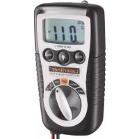
Digital multimeter displaying a 0.11V power supply with two test probes, no visible text or symbols on the device itself.



Laserliner
| DE | 04 |
| EN | 11 |
| NL | 18 |
| DA | 25 |
| FR | 32 |
| ES | 39 |
| IT | |
| PL | |
| FI | |
| PT | |
| SV | |
| NO | |
| TR | |
| RU | |
| UK | |
| CS | |
| ET | |
| RO | |
| BG | |
| EL | |
| SL | |
| HU | |
| SK | |
| HR |
Laserliner
MultiMeter-Pocket
A




CAT III
E
F
natural_image
Diagram of a vehicle's side profile showing a bullet and arrow indicating direction (no text or symbols)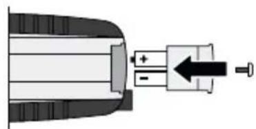
natural_image
Pure mechanical diagram showing a shaft and valve assembly without any text or symbolsG
natural_image
Diagram of a battery pack with two test probes inserted (no text or symbols present)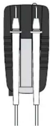
natural_image
Diagram of a dual-pin electronic component with two leads (no text or symbols)H
Laserliner
!
natural_image
Simple electrical circuit diagram showing two batteries connected to a battery with a switch (no text or symbols)natural_image
Illustration of two microphones with a musical note and sound waves, no text or symbols present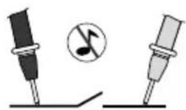
natural_image
Illustration of two dental implants with a musical note symbol (no text or labels)6 ➕ Diodenprüfung
natural_image
Pure electrical circuit symbol for a diode with positive and negative terminals (no text or labels)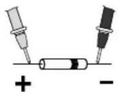
natural_image
Simple diagram showing two test tubes connected to a cylindrical component with plus and minus signs (no text or symbols)Durchlassrichtung
7 μA≈ mA≈ Strommessung DC/AC
Completely read through the operating instructions, the "Warranty and Additional Information" booklet as well as the latest information under the internet link at the end of these instructions. Follow the instructions they contain. This document must be kept in a safe place and passed on together with the device.
Function/Application
Multimeter for taking measurements in the range of overvoltage category CAT III up to max. 1000 V. The meter can be used to measure DC and AC voltages and direct and alternating currents within the specified ranges, as well as for continuity and diode testing. The meter is also fitted with a non-contact voltage detector and has an integrated LED flashlight.
Symbols
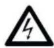
Fig. A: Hazardous electrical voltage warning: Unprotected live components inside the device housing may pose a risk of electric shock.
Fig. B: Danger area warning
Fig. C: Protection class II: The test device has reinforced or double insulation.
Fig. D: Overvoltage category III: Equipment in fixed installations and for applications where specific requirements with regard to the reliability and availability of equipment have to be met, e.g. circuit-breakers in fixed installations and devices used in industrial applications which are permanently connected to the fixed installation.
Safety instructions
- The device must only be used in accordance with its intended purpose and within the scope of the specifications.
- The measuring tools and accessories are not toys. Keep out of reach of children.
- Modifications or changes to the device are not permitted, this will otherwise invalidate the approval and safety specifications.
- Do not expose the device to mechanical stress, extreme temperatures or significant vibration.
- Exercise extreme caution when working with voltages higher than 24 V/AC rms or 60 V/DC. Touching the electrical conductors at such voltages poses a risk of life-threatening electric shocks.
- If the device comes into contact with moisture or other conductive-residue, work must not be carried out under voltage. At and above voltages of 24 V/AC rms / 60 V/DC, the presence of moisture creates the risk of life-threatening electric shocks.
- Clean and dry the device before use.
Laserliner
- When using the device outdoors, make sure that the weather conditions are appropriate and/or that suitable protection measures are taken.
- In overvoltage category III (CAT III - 1000 V), the voltage between the test device and earth must not exceed 1000 V.
- Before taking any measurements, make sure that both the area to be tested (e.g. a line), the test device and the accessories used (e.g. connection cable) are in proper working order. Test the device by connecting it to known voltage sources (e.g. a 230 V socket in the case of AC testing or a car battery in the case of DC testing).
- The device must no longer be used if one or more of its functions fail or the battery charge is weak.
- The device must be disconnected from all power sources and measuring circuits before opening the cover to change the battery(ies) or fuse(s).
- Observe the safety precautions of local and national authorities relating to the correct use of the device and any prescribed safety equipment (e.g. electrician's safety gloves).
- If you have to take hold of the measuring spikes, do so by the grip sections only. Do not touch the measuring contacts whilst the measurement is being taken.
- Make sure that you always select the correct connections and rotary switch position with the correct measuring range for the measurement to be carried out.
- Do not work alone in the vicinity of hazardous electrical installations and only under the guidance of a qualified electrician.
- Disconnect the power supply to the electrical circuit before measuring or checking the diodes, resistance or battery charge.
- Make sure that all high-voltage capacitors are discharged.
- When connecting to a voltage, always connect the black measuring lead first before the red lead. Follow the reverse procedure when disconnecting.
Additional information on use
Observe the technical safety regulations for working on electrical systems, especially: 1. Safely isolating from power supply, 2. Securing to prevent system being switched on again, 3. Checking zero potential, two-pole, 4. Earthing and short-circuiting, 5. Securing and covering adjacent live components.
Safety instructions
Dealing with electromagnetic radiation
- The measuring device complies with electromagnetic compatibility regulations and limit values in accordance with EMC-Directive 2014/30/EU.
- Local operating restrictions – for example, in hospitals, aircraft, petrol stations or in the vicinity of people with pacemakers – may apply. Electronic devices can potentially cause hazards or interference or be subject to hazards or interference.
Safety instructions
Dealing with electromagnetic interference
- The measuring device complies with safety and electromagnetic compatibility regulations and limits in accordance with the Low Voltage Directive 2014/35/EU and electromagnetic compatibility regulations in accordance with the EMC Directive 2014/30/EU.
- Local operating restrictions – for example, in hospitals, aircraft, petrol stations or in the vicinity of people with pacemakers – may apply. Electronic devices can potentially cause hazards or interference or be subject to hazards or interference.
Information on maintenance and care
Clean all components with a damp cloth and do not use cleaning agents, scouring agents and solvents. Remove the battery(ies) before storing for longer periods. Store the device in a clean and dry place.
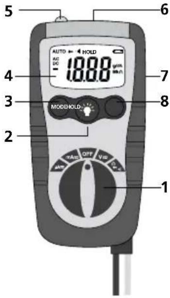
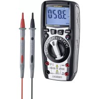
Device description (see Fig. E)
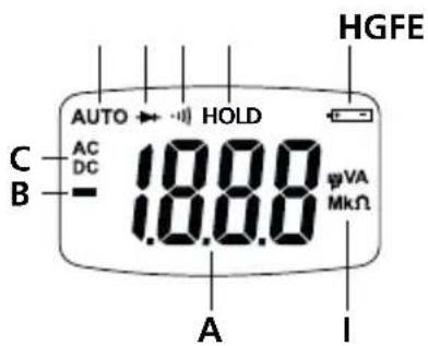
| 1 Rotary switch to set the measuring function | A Measured value display(3.5 segments, 1999 digits) |
| 2 ON/OFF flashlight | B Negative measured values |
| 3 Switch over measuring function | C Direct (DC) or alternating (AC) variables |
| 4 LCD | D Automatic range selection |
| 5 Sensor (non-contact voltage detector) | E Diode test |
| 6 Indicator (non-contact voltage detector) | F Continuity test |
| 7 Holder for test prods | G Actual measurement is retained |
| 8 Hold actual measured value | H Low battery charge |
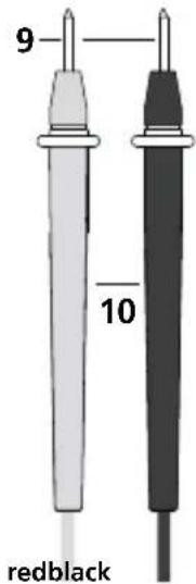
| 9 Measuring contacts: red „+“, black „-” | I Measurement units:mV, V, μA, mA, Ohm,kOhm, MOhm |
| 10 Test prods | Display: O.L: Open line/overflow: measuring circuit not closed or measuring range exceeded |
AUTO OFF function
In order to preserve the batteries, the meter switches off automatically if it is left idle for 15 minutes.
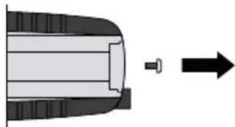
1 Insertion of batteries (see Fig. F)
Open the battery compartment and insert batteries according to the symbols. Be sure to pay attention to polarity.
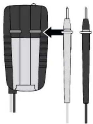
2 Attaching the test prods (see Fig. G)
In order to avoid the risk of injury, the test prods must always be kept in the holder on the rear of the meter when not in use and during transport.
Laserliner
B V≈ Voltage measurement DC/AC
redblack
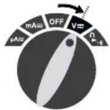
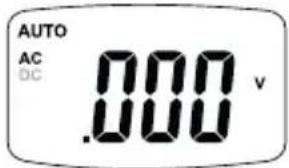
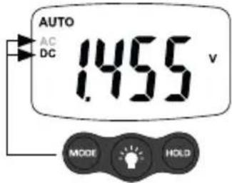
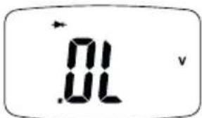
To take a voltage measurement, turn the rotary switch to position „V“ and press the „Mode“ button to set the voltage mode (AC, DC).
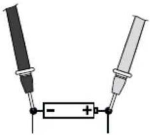
Then connect the measuring contacts to the object to be tested. The measured value acquired and the polarity appear on the display.
natural_image
Simple electrical circuit diagram showing two battery terminals connected to a resistor with polarity markings (no text or symbols)4 Ω Resistance measurement
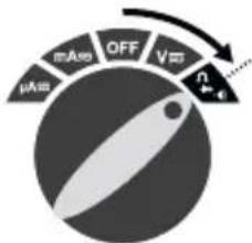
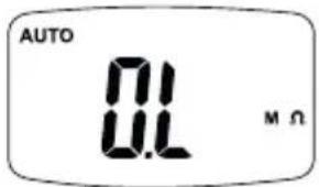
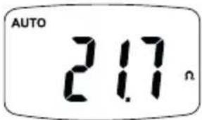
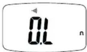
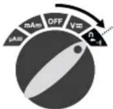
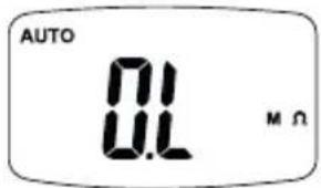
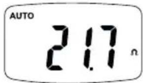
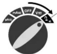
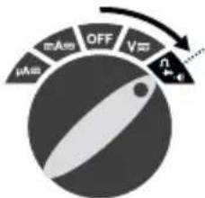
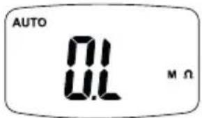
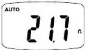
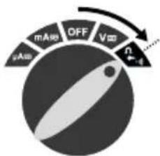
To measure the resistance, turn the rotary switch to position „Ω“. Then connect the measuring contacts to the object to be tested. The measured value acquired appears on the display. If „O.L.“ appears on the display instead of a measured value, either the measuring range has been exceeded or the measuring circuit is not closed or has been interrupted. Resistances can only be measured correctly in isolation; therefore, the components might need to be disconnected from the remainder of the circuit.
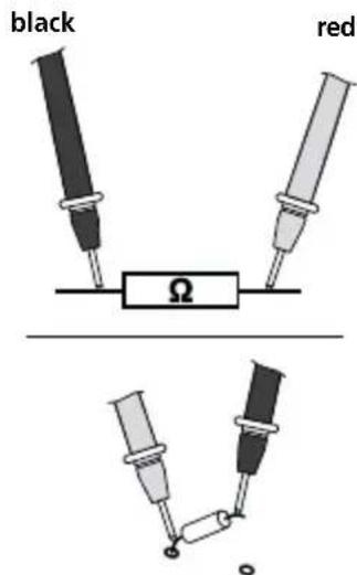

When measuring resistance, to avoid the risk of the results of a measurement being distorted, there must be no traces of dirt, oil, solder spray or other contamination on the test prods.
5 Continuity test
MultiMeter-Pocket
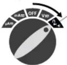
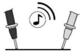
To test continuity, turn the rotary switch to position „Ω“ and press the „Mode“ switch twice to activate the „Continuity test“ function. Then connect the measuring contacts to the object to be tested. A measured value of < 150 ohms is recognised as continuity; this is confirmed by an audible signal. If „O.L.“ appears on the display instead of a measured value, either the measuring range has been exceeded or the measuring circuit is not closed or has been interrupted.
redblack
natural_image
Illustration of two microphones with a musical note and sound waves, no text or symbols present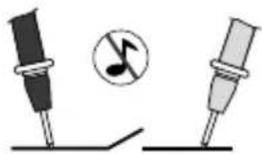
natural_image
Illustration of two musical notes with a circle symbol (no text or labels)6 Diode test
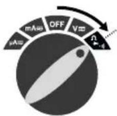
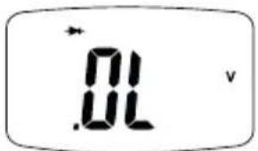
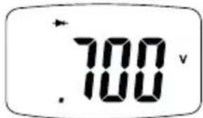
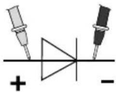
Reverse direction Forward direction
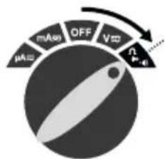
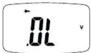
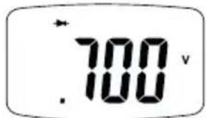
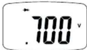
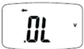
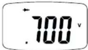
To test the diode, turn the rotary switch to position „Ω“ and press the „Mode“ switch once to activate the „Diode test“ function. Then connect the measuring contacts to the diode. The measured value acquired appears on the display. If „O.L.“ appears on the display instead of a measured value, the diode has either been tested in the reverse direction or is faulty.
red black
natural_image
Pure electrical circuit symbol for a diode with two terminals and polarity indicators (no text or labels)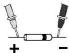
natural_image
Simple diagram showing two test tubes connected to a battery, with plus and minus signs indicating polarity (no text or symbols beyond basic markings)Forward direction
7 μA mA Current measurement DC/AC
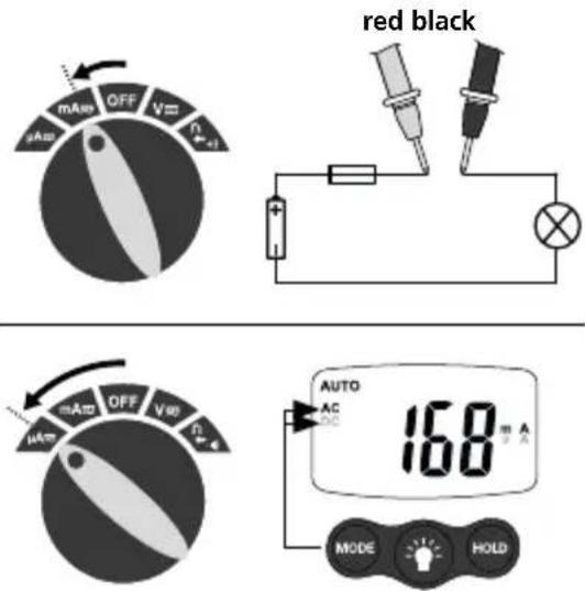
To take a current measurement in the range from 0 to 200 mA, turn the rotary switch to position „mA“ and press the „Mode“ button to set the voltage mode (AC, DC). To take a current measurement in the range from 0 to 200 μA, turn the rotary switch to position „μA“ and press the „Mode“ button to set the voltage mode (AC, DC).
Laserliner
Disconnect the circuit before connecting the meter. Then connect the measuring contacts to the object to be tested. The measured value acquired and the polarity appear on the display. Disconnect the circuit again before disconnecting the meter.

No currents above 200 mA may be measured in the A/mA range! Currents above this level trigger the automatic fuse in the meter.
8 Voltage detection, non-contact (AC warning)
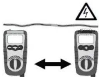
Fig. H: The non-contact voltage detector integrated in the meter is able to detect AC voltages from 100 V to 600 V. Even when the device is switched off, live cables or cable breaks still have to be reckoned with. Run the voltage sensor along the object to be tested (5 - 10 mm). The display lights up if AC voltage is detected.

Non-contact voltage detection is no substitute for conventional voltage testing. As the device detects an electrical field, it will react even to static charge.
Voltage detection, single-pole phase test
Connect the red test prod to the phase or neutral conductor. The red LED only lights up if the phase conductor is live. This function also works if the device is switched off. When the single-pole phase test is carried out on the outer conductor, the indicator function may be adversely affected under certain conditions (e.g. when insulating personnel protective equipment is used or at insulated locations).

The single-pole phase test is not suitable for checking for zero voltage. To do this, you need to carry out a two-pole phase test.
9 Flashlight function
To switch on the flashlight, press and hold down the corresponding button. The light switches itself off automatically as soon as the button is released.
10 Automatic fuse
The meter is equipped with an electronic auto-reset fuse in all ranges and can intercept switching errors under normal operating conditions. If the electronic fuse trips, de-energise the electrical circuit and disconnect the meter. Rectify the switching error. The device will resume normal operation when restarted.
11 Calibration
The meter needs to be calibrated and tested on a regular basis to ensure it produces accurate measurement results. We recommend carrying out calibration once a year.
Technical data
| Function Range Precision | ||
| DC voltage | 200 mV ± (0.5% rdg + 3 digits) | |
| 2.000 V, 20.00 V, 200.0 V600 V | ± (1.2% rdg + 3 digits) | |
| AC voltage 40 - 400 Hz | 2.000 V, 20.00 V ± (1.0% rdg | + 8 digits) |
| 200.0 V, 600 V ± (2.3% rdg + | 10 digits) | |
| DC current | 200.0 μA, 2000 μA | ± (2.0% rdg + 8 digits) |
| 20.00 mA, 200.0 mA | ||
| AC current | 200.0 μA, 2000 μA | ± (2.5% rdg + 10 digits) |
| 20.00 mA, 200.0 mA | ||
| Resistance | 200.0 ΩA± (0.8% rdg + 5 digits) | |
| 2.000 kΩ, 20.00 kΩ, 200.0 kΩA± (1.2% rdg + 5 digits) | ||
| 2.000 MΩA± (5.0% rdg + 5 digits) | ||
| 20.00 MΩA± (10.0% rdg + 5 digits) | ||
| Max. input voltage 600 V AC/DC | ||
| Diode test Test current 1 mA max., open circuit voltage of 1.5 V typical | ||
| Continuity test Audible signal if the resistance is < 150 Ω | ||
| Input resistance >7.5 MΩ (V DC, V AC) | ||
| Polarity Sign for negative polarity | ||
| LCD Up to 1999 (3.5 segments) | ||
| Fuse | mA, μA range: 0.2 A/500 V | |
| Overvoltage | CAT III - 1000 V | |
| Pollution degree | 2 | |
| Degree of protection | IP 64 | |
| Operating conditions | -10°C ... 55°C, Max. humidity 80% rH, no condensation,max. altitude 2000 m | |
| Storage conditions | -10°C ... 60°C, Max. humidity 80% rH | |
| Power supply | 2 x 1.5 V AAA (NEDA24A/IEC LR 03) | |
| Dimensions 120 x 55 x 40 mm | ||
| Weight 145 g | ||
| Test standards | EN 61326, EN 61010-1, EN 61010-2-031 | |
Subject to technical alterations. 18W39
EU directives and disposal
This device complies with all necessary standards for the free movement of goods within the EU.
This product is an electric device and must be collected separately for disposal according to the European Directive on waste electrical and electronic equipment.
Further safety and supplementary notices at:
http://laserliner.com/info?an=ADX
Laserliner
!
natural_image
Simple electrical circuit diagram showing two batteries connected to a battery with a switch (no text or symbols)4 Ω Weerstandsmeting
natural_image
Illustration of musical notes and microphone positions on a stand, no text or symbols present

Diodetest
Doorlaatrichting

μA mA Stroommeting DC/AC
natural_image
Simple electrical circuit diagram showing two battery terminals connected to a resistor with polarity markings (no text or symbols)4 Ω Modstandsmåling

natural_image
Illustration of musical notes and sound waves on two identical stand holders (no text or symbols)

Diodetest
Gennemgangsretning

Laserliner
natural_image
Two identical diagrams showing musical notes and pin positions, no text or symbols presentrojonegro
natural_image
Simple electrical circuit diagram showing two batteries connected to a battery with a switch (no text or symbols)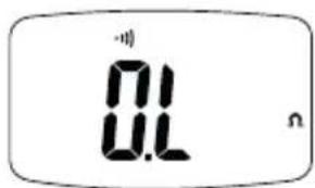
MultiMeter-Pocket
natural_image
Illustration of musical notes and sound waves on two identical stand posts (no text or symbols)Sentido de paso
natural_image
Illustration of a mechanical device connected to a digital multimeter displaying 230 degrees (no text or symbols on the device itself)SERVICE

Umarex GmbH & Co. KG
- Laserliner -

- Laserliner
- MultiMeter-Pocket
- ➕ Diodenprüfung
- μA≈ mA≈ Strommessung DC/AC
- Function/Application
- Symbols
- Safety instructions
- Additional information on use
- Information on maintenance and care
- AUTO OFF function
- Insertion of batteries (see Fig. F)
- Attaching the test prods (see Fig. G)
- B V≈ Voltage measurement DC/AC
- Ω Resistance measurement
- Continuity test
- Diode test
- μA mA Current measurement DC/AC
- Voltage detection, non-contact (AC warning)
- Voltage detection, single-pole phase test
- Flashlight function
- Automatic fuse
- Calibration
- EU directives and disposal
- Ω Weerstandsmeting
- Diodetest
- μA mA Stroommeting DC/AC
- Ω Modstandsmåling
Brand : Laserliner
Model : MultiMeterPocket
Category : Multimeter