eTwist - Thermostat Remeha - Free user manual and instructions
Find the device manual for free eTwist Remeha in PDF.
| Product type | Connected thermostat with gateway |
| Brand | Remeha |
| Model | eTwist |
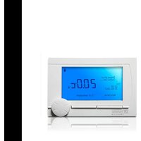
| Thermostat dimensions | 121 x 93 x 28 mm |
| Gateway dimensions | 83 x 145 x 28 mm |
| Thermostat power supply | 4 AAA 1.5 V batteries |
| Gateway power supply | 5 V power adapter |
| Power consumption (gateway) | 4 W max |
| Power consumption (thermostat) | 0.25 mW max |
| Connectivity | Wi-Fi 2.4 GHz, RF 868 MHz (RAMSES) |
| Supported communication protocols | OpenTherm, On/Off, RUB, BSB (depending on gateway model) |
| Operating temperature | 0 °C to 60 °C |
| Storage temperature | -25 °C to 70 °C |
| Allowable relative humidity | 5 % to 95 % (non-condensing) |
| Protection rating | IP21 |
| Cleaning | Slightly damp cloth, no abrasive agents |
| Installation | By a qualified professional |
| Max RF power (Wi-Fi) | +20 dBm |
| Max RF power (868 MHz) | +14 dBm |
| Max cable length (gateway) | 50 m |
Frequently Asked Questions - eTwist Remeha
User questions about eTwist Remeha
0 question about this device. Answer the ones you know or ask your own.
Ask a new question about this device
Download the instructions for your Thermostat in PDF format for free! Find your manual eTwist - Remeha and take your electronic device back in hand. On this page are published all the documents necessary for the use of your device. eTwist by Remeha.
USER MANUAL eTwist Remeha
https://declaration-of-conformity.bdrthermeagroup.com

157668357
en - Information
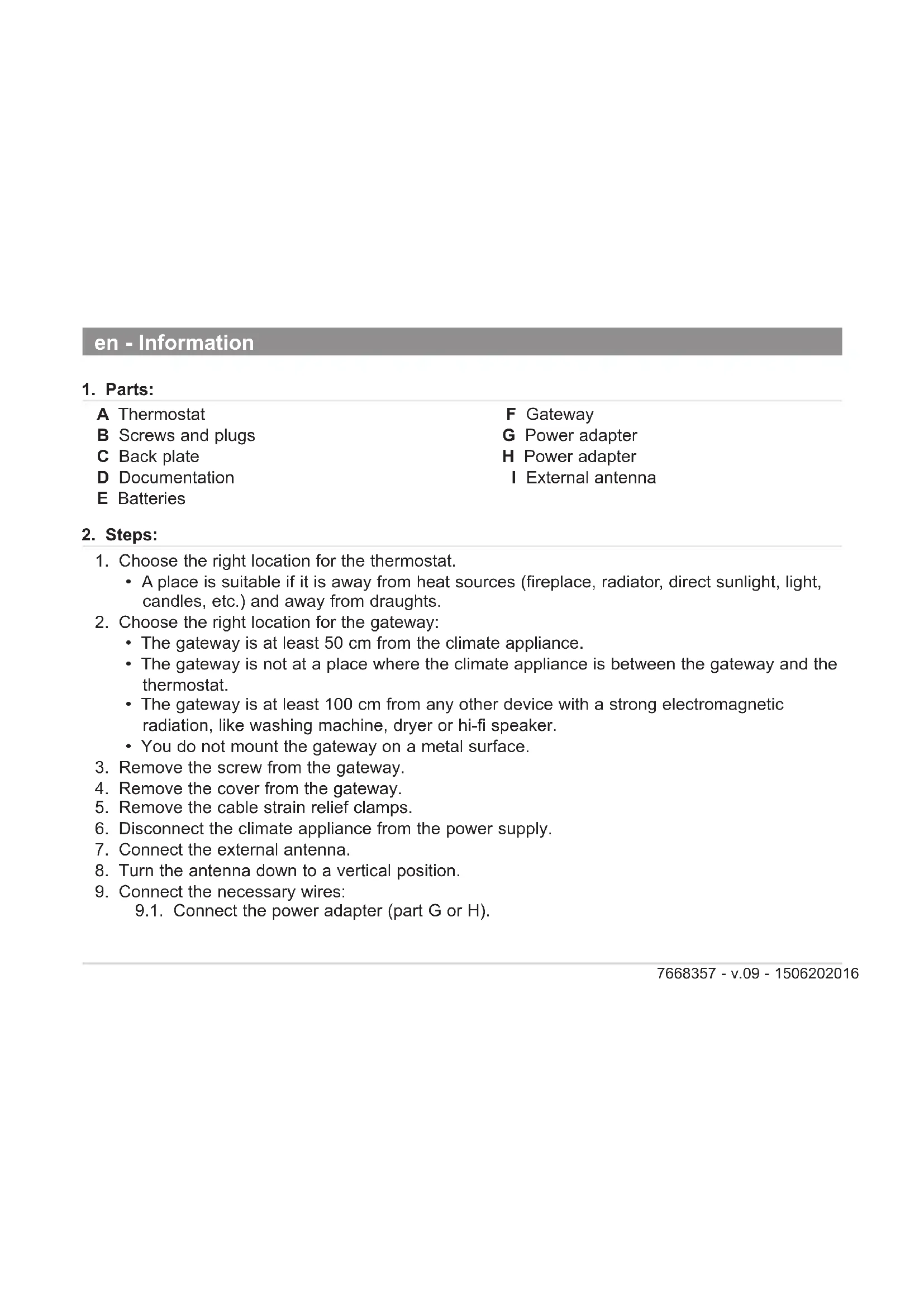
1. Parts:
A Thermostat
B Screws and plugs
C Back plate
D Documentation
E Batteries
F Gateway
G Power adapter
H Power adapter
External antenna
2. Steps:
-
Choose the right location for the thermostat.
-
A place is suitable if it is away from heat sources (fireplace, radiator, direct sunlight, light, candles, etc.) and away from draughts.
-
Choose the right location for the gateway:
-
The gateway is at least 50~cm from the climate appliance.
- The gateway is not at a place where the climate appliance is between the gateway and the thermostat.
- The gateway is at least 100cm from any other device with a strong electromagnetic radiation, like washing machine, dryer or hi-fi speaker.
-
You do not mount the gateway on a metal surface.
-
Remove the screw from the gateway.
-
Remove the cover from the gateway.
- Remove the cable strain relief clamps.
- Disconnect the climate appliance from the power supply.
- Connect the external antenna.
- Turn the antenna down to a vertical position.
- Connect the necessary wires: 9.1. Connect the power adapter (part G or H).
9.2. Connect the climate appliance to the gateway (part F):
| Cable requirements | |||
| Maximum length 20 m 80 m 120 m | |||
| Cross-sectional area 0.8 mm | 2 | 1.0 mm² | 1.5 mm² |
- Connect the climate appliance to the power supply.
- Connect the power adapter (part H).
- Insert the batteries (part E).
- Awaken the thermostat.
- Setup the RF and wi-fi connection:
14.1. Setup the RF communication between the gateway and the thermostat.
14.2. Setup the wi-fi communication between the gateway and the wi-fi router.
- Position and mount the back plate (part C).
15.1. Determine the position of the back plate (part C).
15.2. Drill the 2 marked holes.
15.3. Fit the plugs (part B).
15.4. Secure with screws (part B).
- Mount the thermostat on the back plate.
17.
17.1. Determine the position of the gateway.
17.2. Drill the 2 marked holes.
17.3. Fit the plugs (part B).
17.4. Secure with screws (part B).
- Mount the cable strain relief clamps.
- Mount the cover.
- Secure with screw.
- Test the RF and wi-fi connections.
- If the wi-fi connection should not be sufficient, turn the antenna to a horizontal position.
3. Intended use
- The gateway is designed to operate as a communication interface between a climate appliance
(e.g. boiler, heat pump, etc) and the thermostat.
- The gateway 14 supports the communication protocols OpenTherm, On/Off or RUB.
- The gateway 18 supports the communication protocols OpenTherm, On/Off, RUB or BSB.
4. Installation
The installation of the gateway must be performed by a qualified person.
5. Commissioning
No special procedure is required for the commissioning of the gateway. Consult the user manual of the thermostat for more information if require
6. Reference documentation
On the gateway you will find a label that explains the meaning of the LED indications. The gateway will be a part of your climate system. Consult the product information of the thermostat or climate appliance for more information.
7. Cleaning
The gateway and thermostat can be cleaned with a light moist cloth. Do not use any aggressive or abrasive agents.
8. Trouble shooting
In case of any problems with your thermostat, gateway and/or climate installation, please consult the different user manuals. Consult your installer or sales outlet for unsolved issues.
9. Dismantling
Never open or dismantle the gateway. Consult your installer or sales outlet in case of any problems.
10. Disposal
The gateways are a regular low voltage electronic device. Dispose the gateway in an environmentally friendly way, in accordance with local regulations.
11. Technical specifications
| Dimensions Gateway Thermostat | ||
| Width x height x depth (max. dimensions) 83 x 14 | 45 x 28 mm 121 x 93 x 2 | 8 mm 117 x 107 x 28 mm |
| Max. transmitted RF power Gateway Thermostat | tat | |
| WIFI 2.4GHz +20 dBm - | ||
| 868MHz (RAMSES) +14 dBm +14 dBm |
| Power supply Gateway Thermostat | ||
| Voltage 5V 4 x AAA Batteries 1.5V | ||
| Maximum power consumption 4 W | 0.25 mW |
| Electrical connection | Gateway Thermostat | |
| Maximum cable length | 50 m | - |
| Maximum cable resistance | 2 x 5 Ω | - |
| Ambient conditions | Gateway and Thermostat |
| Storage temperature | from -25°C to +70°C |
| Relative humidity | from 5% to 95%, condensation is not allowed |
| Operating conditions | from 0°C to 60°C |
| Insulation Gateway and Thermostat | |
| IP-classification IP21 | |
| Compliant with standards Gateway and Thermostat | |
| NEN-EN-IEC 60335-1 2012 | Household and similar electrical appliances |
| NEN-EN-IEC 60335-1 2012/C11 2014 | |
| NEN-EN-IEC 60335-1 2012/A11 2014 | |
| 2014/30/EC Low Voltage Directive (LVD) | |
| 2014/53/EU Radio Equipment Directive (RED) | |
| 2015/863/EU RoHS3 Restriction of the use of certain Hazardous Substances in electrical and electronic equipment (RoHS3) | |
| 2012/19/EU Waste Electrical & Electronic Equipment (WEEE) | |
| 1907/06/EC Registration, Evaluation, Authorisation and Restriction of Chemicals (REACH) | |
| EN 55022-2011 Information technology Equipment | |
| EN 55024-2010 Immunity | |
| EN 60068-2-6 Vibration test | |
| EN 60068-2-27 Shock test | |
| OpenTherm V3.1 | |
12. ErP Fiche information
| Gateway + Thermostat Thermostat | (1) | Thermostat (2) | Thermostat (3) |
| Class V VI IV | |||
| Contribution to space heating energy efficiency 3% | 4% | 2% | |
| (1) On modulating boiler. (2) On modulating boiler, with outdoor temperature sensor. (3) On On/Off boiler. |
See the back cover for contact details.
13. EC declaration of conformity
The unit complies with the standard type described in the EC declaration of conformity. It has been manufactured and commissioned in accordance with European directives. The original declaration of conformity is available from the manufacturer.
https://declaration-of-conformity.bdrthermeagroup.com

217668357
fr - Informations
1. Pièces :
https://declaration-of-conformity.bdrthermeagroup.com

277668357
fr - Informations
1. Pièces :
https://declaration-of-conformity.bdrthermeagroup.com

337668357
es - Información
1. Piezas:
https://declaration-of-conformity.bdrthermeagroup.com

397668357
https://declaration-of-conformity.bdrthermeagroup.com

457668357
pt - Informação
1. Peças:
https://declaration-of-conformity.bdrthermeagroup.com

517668357
Copyright
All technical and technological information contained in these technical instructions, as well as any drawings and technical descriptions supplied, remain our property and shall not be multiplied without our prior consent in writing. Subject to alterations.