iSense RF - Thermostat Remeha - Free user manual and instructions
Find the device manual for free iSense RF Remeha in PDF.

User questions about iSense RF Remeha
0 question about this device. Answer the ones you know or ask your own.
Ask a new question about this device
Download the instructions for your Thermostat in PDF format for free! Find your manual iSense RF - Remeha and take your electronic device back in hand. On this page are published all the documents necessary for the use of your device. iSense RF by Remeha.
USER MANUAL iSense RF Remeha
natural_image
3D rendering of a mechanical device showing internal components and housing (no text or symbols visible)R remeha
Inhoudsopgave
natural_image
Diagram showing a device connected to an AC outlet with sound waves, and a separate view of the same device (no text or symbols present)T001080
NL
2. Installatie
- Introduction...... 17
- Installation.... 18
2.1 Location of the base station.... 18
2.2 Connecting the base station.... 20 - Operating principle.... 22
- Commissioning....23
- Fault messages.... 24
- Problems and solutions ...... 26
- Technical data 27
1. Introduction
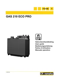
The iBase RF-Base station is the RF transmitter/receiver for the RF-controller. The base station provides wireless communication between the controller and the boiler, via OpenTherm. To ensure two-way communication, information such as the current operating status and service messages are shown on the display of the controller. The base station is positioned by the boiler.
text_image
OTT001080
EN
2. Installation
2.1 Location of the base station
The base station is positioned on the wall near the boiler. Points to note:
- Position the base station in such a way that the boiler is not located between the base station and the controller; doing so can negatively impact the connection signal.
- Position the base station at least 1 metre from equipment with electromagnetic emissions such as ventilation units, washing machines, dryers etc.
- Position the base station so that it has good reception.
To do this, use the signal strength indicator in the controller. The signal strength can be viewed via Menu > Information.

The range of the controller in buildings is generally 30 metres.
Note!
This value is purely an indication. The actual range of the RF signal depends strongly on the local environment. Remember that the number of walls and ceilings (metal or otherwise) can have a (considerable) impact on reception. Other objects that contain metal may also impact reception. These include mirrors and windows with a metal coating, insulating films, tumble driers, washing machines, etc.
EN
2.2 Connecting the base station
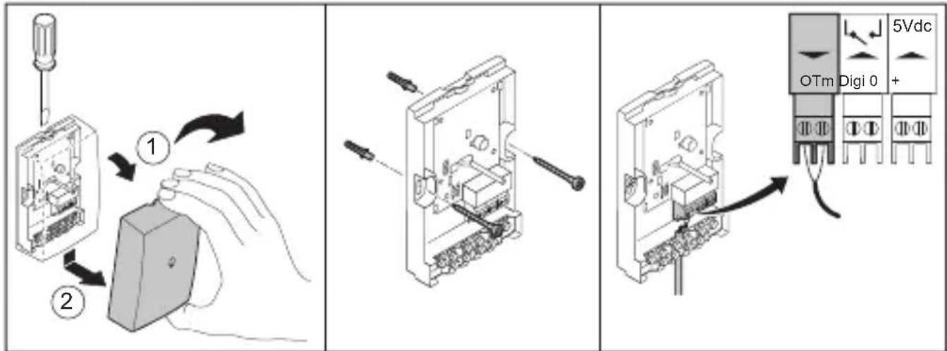
text_image
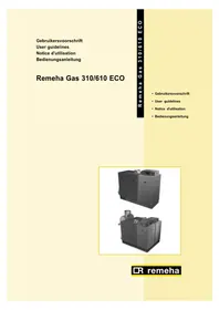
Diagram illustrating three-step electrical connection: screwdriver, switch, and 5VDC power supply with OTm/Digi 0 terminal.R000253-A
- Open the housing by releasing the front of the housing from the base plate using a screwdriver.
- Attach the base plate of the base station to the wall using the supplied screws and plugs. (Keep some space free above the base station to allow for opening the housing again later).
- Connect the OpenTherm connection of the boiler to the OpenTherm connection of the base station (green, indicated by OTm). It makes no
difference here which wire is connected to what contact point of the OpenTherm connection.
- If necessary, connect the wire for the digital input to the orange connection, indicated by DIGI. See the installation and service manual of the controller for information about the functions of the digital input.
- If the boiler does not support OpenTherm Smart Power, you must use an external power adapter (5 Vdc 300mA). Connect this to the power connection (grey, indicated by 5 Vdc). The power adapter is available as an accessory.
- Close the housing of the base station.
The base station is now connected and ready for use. The controller is automatically connected to the base station; see Chapter 4.
3. Operating principle
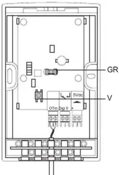
text_image
GR V OTm Digi 0 + 5VdcT001081-A
GR Green status LED
V Connection button
Green status LED
The status LED provides information about the power supply and the RF connection. Fault messages about the power supply and the RF connection are also provided via the status LED; see Chapter 5.
Connection button
This button is used to make a connection between the base station and the controller.
| status LED indication Status | |
| Off Base station has no power. | |
| Flashes once every 4 seconds Base | se station is working normally. |
| Flashes once every second Base | station is trying to connect with the controller. |
4. Commissioning
The base station and the controller are usually automatically connected to each other. The manufacturer ensures this is the case. However, if you replace either of these components the connection must be re-established. This is done as follows:
- Open the housing of the base station.
-
Press the connection button on the base station and hold for three seconds. The status LED now flashes once per second.
-
Activate the Connection option on the controller (see the controller user guide). The status LED on the base station now flashes once every 4 seconds.
-
Check the controller to see if a connection has been established; repeat the procedure if not.
-
Close the housing again.
The base station and the controller are now connected with each other again.
5. Fault messages
A fault message is given by the status LED. This is indicated by the following flash patterns:
- The LED first flashes on for 1 second ( ⚙️ ⚙️ ) and then off for 0.5 seconds ( ● ).
- The LED then flashes a number of times as indicated in the table below to signify the fault.
- Thereafter, the LED is off for at least 0.5 seconds.
This flash pattern is repeated each time.
| Fault indication | Status-LED flashes once: |
| Problem Power | problem. |
| Solution Check | whether the boiler is on and whether the base station is correctly connected. If the boiler does not support OpenTherm Smart Power, then connect an external (5 V DC 300mA) adapter. |
| Fault indication | Status-LED flashes two times: |
| Problem There is no OpenTherm communication for 60 seconds. | |
| Solution Check whether the boiler is on and whether the base station is correctly connected. | |
| Fault indication | Status-LED flashes three times: |
| Problem No connection with controller. | |
| Solution - Check | whether the controller indicates a fault or is on.- Try to re-establish the connection between the controller and the base station; see Chapter 4.- If this does not solve the problem, relocate the controller or the base station or remove obstacles that can interfere with the RF signal, see Chapter 3. |
| Fault indication | Status-LED flashes four times: |
| Problem No RF | communication with controller for 10 minutes. |
| Solution - Check | whether the controller indicates a fault or is on.- Try to re-establish the connection between the controller and the base station; see Chapter 4.- If this does not solve the problem, relocate the controller or the base station or remove obstacles that can interfere with the RF signal, see Chapter 3. |
6. Problems and solutions
| Problem There is no connection or no connection can be made with the controller. |
| Solution Check the status LED, see Chapter 5. |
| Problem There is RF connection but no contact with the boiler (faultcode - F201 on controller). |
| Solution Check whether the boiler is on and check the OpenTherm connection. |
7. Technical data
| General | |
| Dimensions 80 x 60 x 4 | 40 (l x w x h) in mm |
| Power supply Via Open | Therm Smart Power or separate 5 Vdc adapter (300mA) |
| Digital input Potential-free contact (switch) | |
| RF 868.3 MHz, bi-directional secure communication | |
| Ambient conditions | |
| Storage conditions Temperature: -25°C – 60°C | |
| Operating conditions 0°C – 60°C | |
| Wireless range The range of the controller in buildings is generally 30 metres. The range is influenced strongly by the prevailing situation (see Chapter 3). | |

| Quality marks and compliance with standards | |
| Quality marks and compliance with standards | RED 2014/53/EU |
| Drop test: IEC 68-2-32 | |
| RoHS compliant | |
| OpenTherm V3.0 | |
| Protection class IP20 | |
EN
Table des matières
natural_image
Diagram showing two connected devices with a power outlet and signal waves, no text or symbols presentT001080
FR
2. Installation
2.1 Emplacement de Station de base
6. Problems and solutions
natural_image
Simple line drawing of a device with a box and a vertical sensor connected to an external cable (no text or symbols)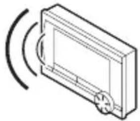
natural_image
Isometric line drawing of a rectangular device with a circular arrow indicating rotation or sound waves (no text or symbols)T001080
2. Installation
text_image
Black and white barcode image with vertical lines on both sides118044
R remeha