
GAS 210 ECO PRO - Central heating boiler Remeha - Free user manual and instructions
Find the device manual for free GAS 210 ECO PRO Remeha in PDF.
User questions about GAS 210 ECO PRO Remeha
0 question about this device. Answer the ones you know or ask your own.
Ask a new question about this device
Download the instructions for your Central heating boiler in PDF format for free! Find your manual GAS 210 ECO PRO - Remeha and take your electronic device back in hand. On this page are published all the documents necessary for the use of your device. GAS 210 ECO PRO by Remeha.
USER MANUAL GAS 210 ECO PRO Remeha
natural_image
Exterior view of a black industrial machine labeled 'Romeba' (no additional text or symbols visible)
3.1 Control panel 25
3.1.1 Start-up the boiler 25
3.2 Reading current values 26
3.3 Adjusting the boiler to the system 27
3.3.1 Changing parameters at user level (without access code) 27
3.4 Setting manual operation ( Symbol) 28
3.5 Taking the boiler out of operation....28
3.5.1 Boiler with frost protection, out of operation for a long time 28
3.5.2 Boiler without frost protection, out of operation for a long time....28
4. Control stops and faults ....29
4.1 General....29
4.2 Control stops and faults 29
4.3 Control stop codes....29
4.4 Fault codes....30
5. Technical specifications .... 32
5.1 Technical data....32
5.2 Type of unit....33
5.3 Operating principle 34
DE
DEUTSCH
Vorwort 36
1. Einleitung 37
Nuttig of handig advies.

1 = Display 5 = [CV temperatuur] of [-]-toets
2 = [Menu]-toets 6 = [+]-toets
3 = [Schoorsteenveger]-toets 7 = [enter]-toets of [Service] indicatie
4 = [Escape] of [RESET]-toets 8 = Aan/uit schakelaar
This user guide, which contains a lot of practical information about the Remeha Gas 210 ECO PRO, a High efficiency central heating unit, is mainly intended for end users.
It contains important instructions for safe and trouble-free operation of the boiler before commissioning and during operation.
Read these instructions carefully before putting the boiler into operation, familiarise yourself with its control functions, operation and strictly observe the instructions given. Failure to do so may invalidate warranty or prevent the boiler from operating.
The data published in these technical instructions is based on the latest information (at date of publication) and may be subject to revisions.
We reserve the right to continuous development in both design and manufacture, therefore any changes to the materials or technology employed may not be retrospective nor may we be obliged to adjust earlier supplies accordingly.
1. Introduction
1.1 Pictograms used
The following pictograms are used in this document to emphasise certain instructions. This is in order to increase your personal safety and to safeguard the technical reliability of the boiler. The pictograms used are:

Useful advice.

Important instruction for carrying out an action.

Possible risk of bodily injury or material damage to boiler, ing or environment.

Possible risk of electrical shocks. Serious bodily injury may occur.
1.2 Important instructions
Your installer usually supplies user guidelines for the entire installation. Follow at first these guidelines (if available).

Work on the boiler
Installation, commissioning, maintenance and repair work may only be carried out by suitably qualified specialist installers in accordance with the applicable national and local standards and guidelines.
Instruction and warning labels on the boiler must never be removed or covered and must be clearly legible throughout the entire service life of the boiler. Generally applicable safety instructions related to accident prevention must be consulted in addition to the information supplied in this technical documentation.

Keep this document near to the installation.
2. Safety
Adhere strictly to the specific safety instructions.

Can you smell gas? Proceed as follows:
Do not smoke and avoid fire and sparks
- Do not operate electrical switches
- Close the gas cock
- Open doors and windows
- Warn those present and leave the building together.
- Call your gas suppliers / installer once you are outside the building, TRANSCO tel. 0800 111 999.

Can you smell flue or combustion gases? Proceed as follows:
• Take the plug out of the socket
- Open doors and windows
- Warn those present and leave the building together.
- Call your installer once you are outside the building.

Installation location for the boiler!
- Do not store or use any flammable materials, aggressive substance and/or aerosols near the boiler.
• The installation area must be frost-free.

Service once a year
The boiler must be inspected once a year by a qualified engineer to ensure optimum, safe operation.
3. Control
3.1 Control panel
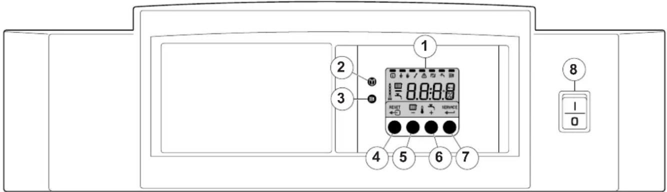
The boiler's control panel contains four function keys, a menu key, a chimney-sweeping key, an on/off switch and a display.
text_image
1 2 3 4 5 6 7 8 I 0fig. 01 Control panel
114492LTAL21H008a
1 = Display 5 = [Central heating temperature] or [-] key
2 = [Menu] key 6 = [+] key
3 = [Service engineers] key 7 = [enter] key or [Service] indicator
4 = [Escape] or [reset] key 8 = On/off switch
The display has four positions and several symbols and provides information about the operating status of the boiler and any faults. Numbers, dots and/or letters may be shown.
The symbols above the function keys indicate what the function of the relevant keys is at that moment.
If no key is pressed for three minutes, the display lighting switches off and only the 📄 and 🔔 symbols are displayed. Press any key; the current boiler status and the current operating code appear on the display. This is always displayed in the event of a fault.
3.1.1 Start-up the boiler
- First follow the guidelines that your installer supplied for the entire installation. If not available: follow the instructions below.
- Check the water pressure in the installation (min. 0.8 bar). Fill up when necessary.
- Open the main gas cock.
- Put the boiler control to heat demand.
- Start the circulation pump.
- Switch on the electrical supply to the boiler and the on/off switch on the instrument panel; the Gas 210 ECO PRO will perform the start-up program.
The following appear successively in the display:
- a short display test, whereby all of the display's segments are visible;
text_image
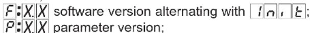
F: X. X software version alternating with 1n, t; P: X. X parameter version;- Afterwards (depending on the operating status), the following may appear on the display:
N : L (flashes) : live and nutral wires are wrongly connected; change wires on the 230V terminal strip!
| With a heat demand: |
| 1 Boiler starts |
| 2 Burner starts |
| 3 Central heating operation; briefly in part load then in full load |
| When a heat demand ceases: |
| 5 Burner stops |
| 6 Boiler stops |
| 7 Stand-by mode |
table 01 Normal operation
3.2 Reading current values
flowchart
graph TD
    A["○"] --> B["○"]
    B --> C["← SET 3"]
    C --> D["○ +"]
    D --> E["○"]
    E --> F["○"]
    F --> G["○ +"]
    G --> H["○ +"]
    H --> I["○ +"]
    I --> J["○ +"]
    J --> K["○ +"]
    K --> L["○ +"]
    L --> M["○ +"]
    M --> N["○ +"]
    N --> O["○ +"]
    O --> P["○ +"]
    P --> Q["○ +"]
    Q --> R["○ +"]
    R --> S["○ +"]
    S --> T["○ +"]
    T --> U["○ +"]
    U --> V["○ +"]
    V --> W["○ +"]
    W --> X["○ +"]
    X --> Y["○ +"]
    Y --> Z["○ +"]
    Z --> AA["○ +"]
    AA --> AB["○ +"]
    AB --> AC["○ +"]
    AC --> AD["○ +"]
    AD --> AE["○ +"]
    AE --> AF["○ +"]
    AF --> AG["○ +"]
    AG --> AH["○ +"]
    AH --> AI["○ +"]
    AI --> AJ["○ +"]
    AJ --> AK["○ +"]
    AK --> AL["○ +"]
    AL --> AM["○ +"]
    AM --> AN["○ +"]
    AN --> AO["○ +"]
    AO --> AP["○ +"]
    AP --> AQ["○ +"]
    AQ --> AR["○ +"]
    AR --> AS["○ +"]
    AS --> AT["○ +"]
    AT --> AU["○ +"]
    AU --> AV["○ +"]
    AV --> AW["○ +"]
    AW --> AX["○ +"]
    AX --> AY["○ +"]
    AY --> AZ["○ +"]
fig. 02 Reading current values
The following current values can be read in the 'information menu' ⓘ
-5t = Status
- 5 5 = Sub status
- Ⓤ☐ = flow temperature [°C];
- ^2 = return temperature [°C];
- = outside temperature [°C];
- E δ = boiler block temperature [°C];
- 5P = internal set point [°C];
- F L = ionisation current [μA];
- n F = fan rotation speed [rpm];
- = water pressure [mbar];
- P o. = relative output supplied [%];
The current values can be read as follows:
- Press the ⏻ key, the ⓘ symbol will then flash, confirm with the ← key;
- Press the [+) key again so that 5|t appears alternating with 3, the actual status;
- Press the [+) key again so that 5 appears alternating with , the actual sub status;
- Press the [+] key again so that ☐☐ appears, alternating with, for example, ☐☐0°C, the actual flow temperature;
- Press the [+] key repeatedly so that the remaining temperatures also appear;
- Press the [+] key again so that 5P appears, alternating with, for example, 88^ , the actual internal set point;
- Press the [+] key again so that F appears alternating with, for example, 70 , the actual ionisation current;
-
Press the [+) key again so that nF appears alternating with, for example, 3000 (rpm), the actual fan rotation speed;
-
Press the [+] key again until appears alternating and, for example, 3 . 0 bar, the actual water pressure (if no water pressure sensor is connected, --.bar appears);
- Press the [+] key again until P_0 . appears and, for example, 78% , the actual modulation percentage;
- Press the [+] key again, the read-out cycle starts again with S E, etc;
- Press the ←→ key twice to return to the display with the current operating status.
3.3 Adjusting the boiler to the system
The boiler's control unit is set to the most common central heating systems. With these settings, practically all central heating systems will work well. However, the user or the installer can optimise the parameters as he/she wishes.
3.3.1 Changing parameters at user level (without access code)
The following settings can be changed at user level:
= Maximum flow temperature [^], adjustable between 20 and 90^;
P 2 = Pump post-circulation time 0..98 mins, 99 is continuous; P 3 = Boiler control; central heating on/off.
0 = Central heating off
1 = Central heating on (= factory setting)
P 4 = Display
0 = Simple display
1 = Comprehensive display
2 = Display automatically goes to simple after three minutes (factory setting)
The parameters can be changed at user level as follows:
- Press the ⏻ -key several times until the 🔔 symbol flashes in the menu bar;
- Select the users menu using the ← -key, P: I appears (the / flashes);
- Press the [+] -key; P:2 appears (the 2 flashes);
- Press the ← -key again; 3 (min) appears and flashes: (factory setting);
- Change the value by pressing the [-] -key or the [+] -key, in this case for example to 15 min, with the [-] -key;
- Confirm the value with the ← -key, P2 appears (the 2 flashes);
- Press the ←- key twice, the boiler enters the current operating status.

The P1 to P4 settings can be changed in the same way as P2.
fig. 03 Changing parameters
3.4 Setting manual operation ( Symbol)
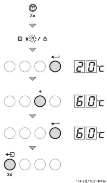
flowchart
graph TD
    A["3x"] --> B["Diode icon"]
    B --> C["Downward arrow"]
    C --> D["○ ○ ○"]
    D --> E["20°C"]
    C --> F["Downward arrow"]
    F --> G["○ ○ +"]
    G --> H["○ ○"]
    H --> I["60°C"]
    G --> J["Downward arrow"]
    J --> K["○ ○ ○"]
    K --> L["60°C"]
    J --> M["Downward arrow"]
    M --> N["2x"]
    N --> O["○ ○ ○"]
    O --> P["114492LTAL21H019a"]
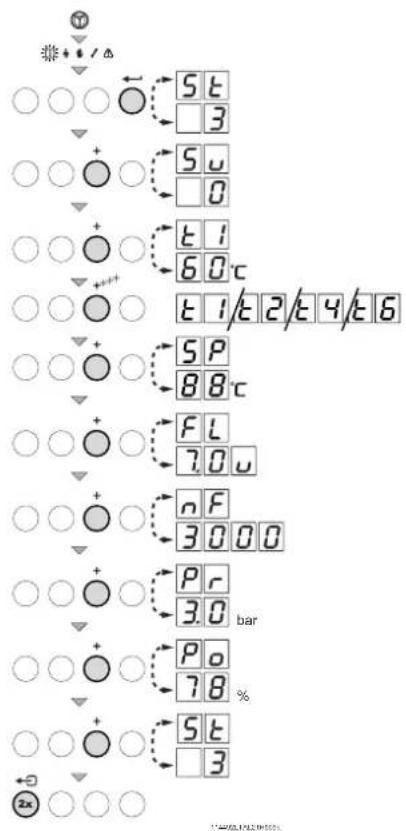
In some cases, it may be necessary to set the boiler to manual operation, for example when the controller has not yet been connected. The boiler can be set to automatic or manual operation under the 🔊 symbol. Do this as follows:
- Press the ⏻ -key several times until the 🔊 symbol flashes in the menu bar;
- Press the -key once, either the minimum flow temperature or R U E O (only if an external sensor has been connected) will appear in the display; the flow temperature is determined by the internal heating curve;
- Press the [+] -key to increase this value in manual operation temporarily;
- Confirm with the ← -key;
• The boiler is now set to manual operation; - Press the ←→ -key twice to exit manual operation; the boiler enters operating status.

Manual operation keeps active after power breakdown.
fig. 04 Setting manual operation
3.5 Taking the boiler out of operation
The boiler must be switched off for maintenance or repair work. If the central heating system is not going to be used for a long time (for example, during holidays in frost-free periods), it is advisable to put the boiler out of operation.
3.5.1 Boiler with frost protection, out of operation for a long time
- Set the controller low, for example to 10^ ;
The Gas 210 ECO PRO will now only come into operation to protect itself against freezing (= depending on parameter 33). To prevent radiators and the system from freezing in rooms where there is a risk of frost (e.g. garage or storage room), a frost thermostat can be connected to the boiler. The boiler will then keep the radiators in that room warm.

This frost protection does not work if the boiler is out of operation.
3.5.2 Boiler without frost protection, out of operation for a long time
• Isolate the mains power supply from the boiler;
- Close the boiler gas cock.

Tap the boiler and central heating system if you are not going to use your home or the building for a long time and there is a chance of frost.
4. Control stops and faults
4.1 General
The boiler is fitted with an advanced control unit. The heart of the control is a microprocessor, the abc ^® , which both protects and controls the boiler.
Before calling in the installing engineer, first check if:
- the gas cock is open
- the maximum operating temperature setting is high enough
- the boiler control has been correctly set
- the main switch is on
- a sufficient water flow is possible (the radiator valves are entirely opened)
- the water pressure is sufficient (> 0.8 bar).
Note down the failure message before resetting. Reset the failure by pressing the reset-key on the instrument panel.
4.2 Control stops and faults
Control stop:
The control stop is a (temporary) boiler operating mode due to an abnormal situation. The boiler switches to the neutral position so that it can return to a normal state. The display then shows the shutdown status (with code 9) again. The boiler control unit will, at first, try several times to start the boiler again. The boiler shall operate again when the causes of the control stop have been removed.
Fault:
If the shutdown condition still exists even after various automatic control unit start attempts have been made or if a non-reproducible phenomenon has arisen, the boiler switches to fault mode (also known as lock-out). The boiler can only resume operation if the cause of the fault is rectified and the 'RESET button' is pressed
4.3 Control stop codes
The boiler display will show code 9.
The control stop codes can be read out as follows:
- Push the Ⓜ -key, and then the ← -key;
• The display shows 5t = 9; - Push the [+] -key one time; the display shows 5 and the control stop code.
• Note down the control stop code.

The boiler shall start automatically when the causes of the control stop have been removed.
The list enumerates only control stop codes you might be able to solve by yourself. If the control stop code continues to appear after you seem to have rectified the fault, please contact your service engineer. For control stop codes not mentioned in this list also contact your service engineer.
| Code 5u | Description Possible cause | Check/solution | |
| 3 | Maximum heat exchanger temperature exceeded | No flow or insufficient flow during heat demand | Check:That the system has been correctly bledWater pressure in the system |
| 4 | Maximum heat exchanger temperature increase exceeded | No flow or insufficient flow | Check:That the system has been correctly bledWater pressure in the system |
| 5 | Maximum difference between heat exchanger and return temperature exceeded | No flow or insufficient flow during heat demand | Check:That the system has been correctly bledWater pressure in the system |
| 6 | Maximum difference between heat exchanger and flow temperature exceeded | No flow or insufficient flow during heat demand | Check:That the system has been correctly bledWater pressure in the system |
| 14 | Water pressure too low | Water pressure non-existent or too lowWater leakage | Check:Water pressure in the systemMinimum water pressure |
| 15 | Gas pressure too low • No flow or insufficient flow | Check:That the gas cock is fully opened | |
| 22 | No flame during operation • No ionisation current | Check:That the gas cock is fully opened adjusted and working correctlyWhether the air supply or flue gas discharge are blocked | |
| 24 | VPS test failed | Gas pressure non-existent or too low | Check:That the gas cock is fully opened |
table 02 Control stop codes
4.4 Fault codes
The boiler displays the fault codes as follows:
E 12 (the display shows the ⚠ symbol and the fault code flashes). The meaning of the fault codes can be found in the fault table, see table 03.
In the event of faults, proceed as follows:
• Note the fault code.

The fault code is needed to find the cause of the fault quickly and correctly.
- Press the "RESET -key" for 2 seconds. If the fault code continues to appear, look for the cause in the following fault table and rectify the fault.

If the display does not show RESET but SERVICE, the boiler must be switched off and switched on again after 10 seconds before the fault can be reset.
The list enumerates only fault codes you might be able to solve by yourself. If the fault code continues to appear after you seem to have rectified the fault, please contact your service engineer. For fault codes not mentioned in this list also contact your service engineer.
| Fault code | Description Possible cause Check/solution | ||
| E:04 | Heat exchanger temperature exceeded below normal range | No or to little flow | Check:if system has been correctly bledwater pressure in the system |
| E:05 | Heat exchanger temperature exceeded above normal range | ||
| E:08 | Return temperature exceeded below normal range | No or to little flow | Check:if system has been correctly bledwater pressure in the system |
| E:09 | Return temperature exceeded above normal range (high limit thermostat) | ||
| E:10 | Too great a difference between heat exchanger and return temperature | No or to little flow | Check:if system has been correctly bledwater pressure in the system |
| E:11 | |||
| E:12 | Trap protection activated | Pressure in flue gas discharge duct is (was) too high | Check:that the trap is not empty; top up if necessaryblockage in flue gas discharge coveredtrap is blocked |
| E:14 | 5 failed burner starts | Ignition spark, but no flameFlame, but insufficient ionisation | is the gas cock opened? |
| E:15 | 5 failed gas leakage controls • No | or to little gas pressure • Is the gas cock opened? | |
table 03 Fault codes
5. Technical specifications
5.1 Technical data
| Boiler type Gas 210 ECO PRO Unit 210-80 210-120 210-160 210-200 | ||||||
| General | ||||||
| Number of sections 3 4 5 6 | ||||||
| Input control - Modulating, 0-10 V or on/off | ||||||
| Nominal output (80/60°C) Pn | min - maxFactory setting | kW 16 - 87 | 22 - 115 29 | - 166 | 39 | - 200 |
| kW | 87 | 113 | 166 | 200 | ||
| Gas and flue gas side | ||||||
| Inlet gas pressure G20 | mbar | 17 - 30 | ||||
| Inlet gas pressure G20 BE | mbar | 17 - 25 | ||||
| Inlet gas pressure G25 | mbar | 20 - 30 | ||||
| Gas consumption G20 | min - max | m _0^3/h | 1,8 - 9,4 | 2,4 - 13,0 | 3,3 - 18,0 | 4,3 - 21,7 |
| Gas consumption G25 | min - max | m _0^3/h | 2,1 - 11,0 | 2,8 - 15,1 | 3,8 - 20,9 | 5,1 - 25,2 |
| NO _x emissions | mg/kWh | < 62 | ||||
| NO _x emissions (O _2 = 0%, dry) | ppm | < 35 | ||||
| Central heating side | ||||||
| High limit temperature | °C | 110 | ||||
| Operating temperature range | °C | 20 - 90 | ||||
| Minimum water working pressure | bar | 0.8 | ||||
| Maximum water working pressure PMS | bar | 6 | ||||
| Water content | litres | 12 | 16 | 20 | 24 | |
| Electrical | ||||||
| Mains voltage | V/Hz | 230/50 | ||||
| Input power (without pump) | min | Watt | 4 4 4 4 | |||
| max | Watt | 125 | 193 | 206 | 317 | |
| Insulation class | IP | 20 | ||||
| Other | ||||||
| Weight excluding water | kg | 115 | 135 | 165 | 188 | |
| Environment temperature | °C | 0 - 40 | ||||
| Noise level at a distance of 1 m from the boiler (enclosed version) | dB(A) | ≤ 59 | ||||
| Colour of casing | RAL | 2002 (red)/7037 (grey) | ||||
table 04 Technical data
5.2 Type of unit
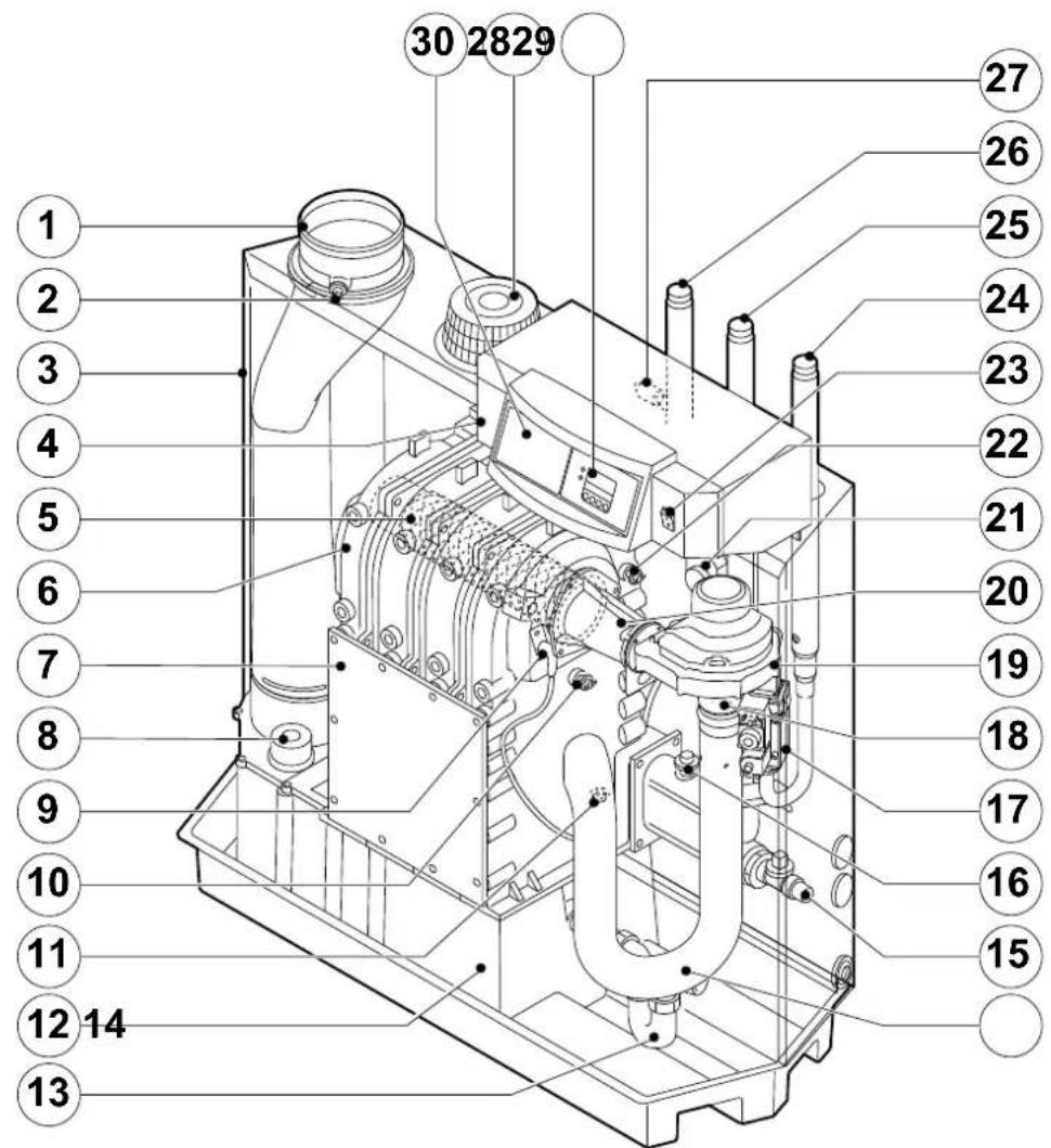
text_image
30 2829 1 2 3 4 5 6 7 8 9 10 11 12 14 13 27 26 25 24 23 22 21 20 19 18 17 16 15114492LTAL21H016b
fig. 05 Cross-section
- Flue gas discharge 11. Return temperature sensor 21. Flue gas switch
- O₂/CO₂ measuring point 12. Condensate collector 22. Flow temperature sensor
- Air box 13. Condensate trap 23. On/off
- Control panel 14. Air silencing tube
- Burner
- Heat exchanger
- Inspection hatch
- Inspectionhatch for condensate collector
- Ignition pin
- Boiler heath exchanger sensor
- Filling and drain cock 25. Return connection
- Water pressure switch (option) 26. Flow connection
- Gas multiblock 27. Thermostat pocket
- Venturi 28. Display
- Fan
- Combustion air supply
- Mixing tube 30. Facility for built-in weather compensator
24. Gas connection
5.3 Operating principle
The inlet side of the fan is fitted with a venturi, where air and gas are mixed according to a fixed ratio. When there is a heat demand, the fan will pre-vent. The fan draws in the combustion air, which is mixed with the gas to optimum effect in the venturi. The fan moves the homogenous gas/air mixture through to the burner. The mixture is then ignited by the combined ignition and ionisation electrode, which also monitors the flame. Combustion then takes place. Following combustion, the hot flue gases pass through the cast aluminium heat exchanger. Here, the flue gases release their heat to the heating water in the heat exchanger. The heat output of the boiler is controlled on the basis of the settings and the prevailing water temperatures that are measured by the temperature sensors. With flue gas temperatures below dew point (approx. 55°, the temperature at which the water vapour in the flue gases starts to condense), the water vapour in the flue gases will condense in the lower part of the heat exchanger. The heat released during this condensation process (called latent heat or heat of condensation) is also transferred to the heating water. The condensed water is discharged through a trap. The flue gases flow through the condensate collector and are discharged via the flue gas discharge pipe.
The advanced control system of the boiler, the abc ^® , guarantees extremely reliable heat supplies. This means that the boiler responds quickly and efficiently to negative environmental influences (such as hydraulic flow problems, air flow problems, etc.). If problems of this kind occur, the boiler will not lock out, but initially modulate down and, depending on the nature of the problem, switch off temporarily (shutdown or control stop) and try again after a pre-determined time. Providing the situation is not hazardous, the boiler will always continue to attempt to provide heat. For a continuous supply of heat, the boiler requires a minimum flow of 30 % of the nominal water flow at the relevant design temperatures. The boiler can be equipped with a second return (available as an accessory). The second return can contribute additional efficiency if the installation includes different temperature groups.
GB Remeha Commercial UK
Innovations House
3 Oaklands Business Centre
Oaklands Park
Wokingham
RG41 2FD
Tel: +44 118 9783434
Fax: +44 118 9786977
boilers@remeha.co.uk.
www.remeha.co.uk
BE Thema S.A.
Koralenhoeve 10 (KMO-zone
Kapelleveld)
2160 WOMMELGEM
België
Tel +32(0)3 230 71 06
Fax +32(0)3 354 54 30
E-mail: info@remeha.be
Internet: www.remeha.be
DE Remeha GmbH
Rheiner Strasse 151
48282 Emsdetten
Tel: +49 2572 9161 - 0
Fax: +49 2572 9161 - 102
E-Mail: info@remeha.de
All technical and technological information contained in these technical instructions, as well as any drawings and technical descriptions furnished by us remain our property and may not be multiplied without our prior consent in writing.
27102015