
Gas 610 ECO - Central heating boiler Remeha - Free user manual and instructions
Find the device manual for free Gas 610 ECO Remeha in PDF.
| Product type | Central heating boiler |
| Brand | Remeha |
| Model | Gas 610 ECO |
| Category | Condensing boiler |
| Fuel | Gas (natural or propane, depending on setting) |
| Boiler type | Modulating, condensing |
| Minimum hydraulic pressure | 0.8 bar |
| Maximum flow temperature | 90 °C (adjustable) |
| Pump post-circulation | 3 minutes (adjustable) |
| Power supply | 230 V / 50 Hz |
| Display | LCD display (codes and temperatures) |
| Controls | Main switch, Reset, Mode, Step, Store, +, - buttons |
| Main functions | Power modulation, condensation, pre-ventilation, flame control, post-circulation |
| Safety | Air pressure switch, gas tightness check, ionization electrode, anti-freeze safety |
| Routine maintenance | Check hydraulic pressure, purge the system, external cleaning |
| Error code | 3-digit display with dots, allows quick diagnosis |
| Note | Do not modify the boiler yourself, contact an installer |
Frequently Asked Questions - Gas 610 ECO Remeha
User questions about Gas 610 ECO Remeha
0 question about this device. Answer the ones you know or ask your own.
Ask a new question about this device
Download the instructions for your Central heating boiler in PDF format for free! Find your manual Gas 610 ECO - Remeha and take your electronic device back in hand. On this page are published all the documents necessary for the use of your device. Gas 610 ECO by Remeha.
USER MANUAL Gas 610 ECO Remeha
natural_image
Exterior view of a gray industrial machine or gasifier unit (no visible text or symbols)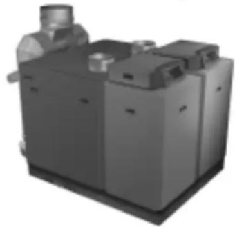
natural_image
3D rendering of a gray industrial machine with a worker in the background (no visible text or symbols)R remeha
INHOUD
Algemeen 4
Werkingsprincipe 4
Principle of the boiler operation 8
Layout of the instrument panel 10
Commissioning the boiler 11
Putting the boiler out of operation 11
Venting of the installation 11
Trouble shooting 11
TABLE DES MATIERES
Generalites 12
text_image
Technical diagram of an industrial machine with numbered components and control panel layoutafb. 01 Doorsnede Remeha Gas 310 ECO
00.31H.79.00002

text_image
Technical diagram of an electrical equipment cabinet with numbered components and piping connectionsThese user guidelines contain useful and important information for the correct operation and maintenance of the Remeha Gas 310/610 ECO. Furthermore, important instructions are given to ensure safe and trouble-free boiler operation. Read these instructions carefully before putting the boiler into operation, familiarise yourself with
its operation and strictly observe the instructions given. Your installer usually supplies user guidelines for the entire installation. Follow at first these guidelines (if available).
Remark: As a user you are not allowed to change any part of the boiler.
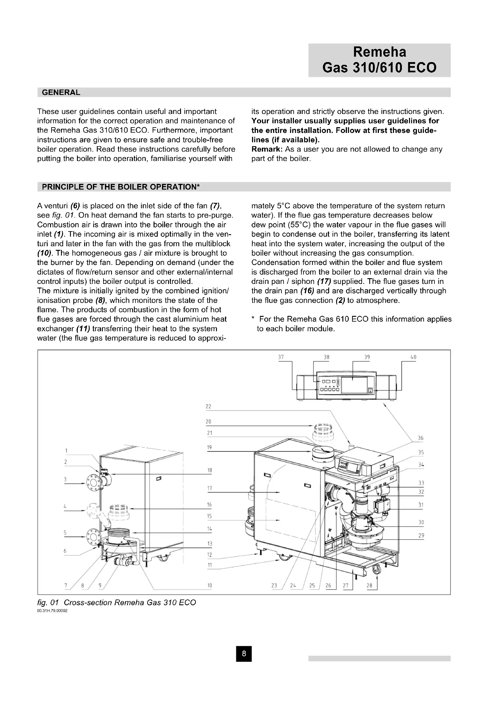
A venturi (6) is placed on the inlet side of the fan (7), see fig. 01. On heat demand the fan starts to pre-purge. Combustion air is drawn into the boiler through the air inlet (1). The incoming air is mixed optimally in the venturi and later in the fan with the gas from the multiblock (10). The homogeneous gas / air mixture is brought to the burner by the fan. Depending on demand (under the dictates of flow/return sensor and other external/internal control inputs) the boiler output is controlled.
The mixture is initially ignited by the combined ignition/ionisation probe (8), which monitors the state of the flame. The products of combustion in the form of hot flue gases are forced through the cast aluminium heat exchanger (11) transferring their heat to the system water (the flue gas temperature is reduced to approxi-
mately 5^ C above the temperature of the system return water). If the flue gas temperature decreases below dew point ( 55^ C) the water vapour in the flue gases will begin to condense out in the boiler, transferring its latent heat into the system water, increasing the output of the boiler without increasing the gas consumption.
Condensation formed within the boiler and flue system is discharged from the boiler to an external drain via the drain pan / siphon (17) supplied. The flue gases turn in the drain pan (16) and are discharged vertically through the flue gas connection (2) to atmosphere.
* For the Remeha Gas 610 ECO this information applies to each boiler module.
text_image
Technical diagram of an industrial machine with numbered components and control panel layoutfig. 01 Cross-section Remeha Gas 310 ECO 00.31H.79.00002

text_image
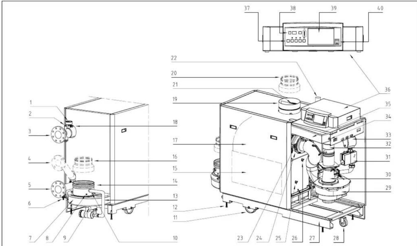
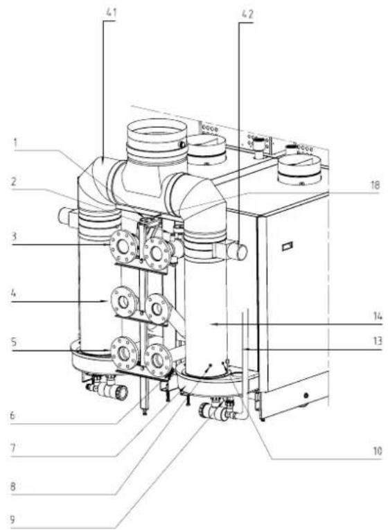
Technical diagram of an electrical equipment cabinet with numbered components and piping connectionsfig. 02 Rear view Remeha Gas 610 ECO 00.61H.00002
1 Pressure gauge
2 Connection point for optional external thermostat
3 Flow connection
4 Connection point optional second return
5 Return connection
6 Fill and drain cock
7 Drain pan
8 Temperature sensor - flue gas
9 Condense connection
10 Combustion test point O 2 /CO 2
11 Line wheel
12 Set screw
13 Condense drain hose
14 Flue gas outlet
15 Inspection hatch
16 Adapter ∅ 250/∅ 200 (option)
17 Heat exchanger
18 Temperature sensor - flow
19 Air supply
20 Air inlet plate
21 Adapter ∅ 200/∅ 250 (option)
An intelligent, advanced boiler control* ('abc®') continuously monitors the boiler conditions, varying the heat output to suit the system load. The control is able to react to external "negative" influences in the rest of the system (flow rates, air / gas supply problems) maintaining boiler output for as long as possible without resorting to a lock out condition. At worst the boiler will reduce
22 Gas connection
23 Inspection glass
24 Combined ignition/ionisation probe
25 Temperature sensor - return
26 Temperature sensor - heat exchanger
27 Frame
28 Turn wheel
29 Air supply fan
30 Venturi
31 Gas multiblock
32 Non return valve
33 Gas filter
34 Differential pressure switch
35 Air box
36 Instrument panel
37 Boiler setting keys
38 Read-out display
39 Optional incorporateable weather compensator rematic®
40 On/off switch
41 Flue gas collector
42 Flue gas damper
it's output and/or shut down (shut off mode) awaiting the "negative" conditions to return to normal before restarting. The 'abc®' control cannot override the standard flame safety controls.
* The Remeha Gas 610 ECO has a boiler control unit on each boiler module.
LAYOUT OF THE INSTRUMENT PANEL
text_image
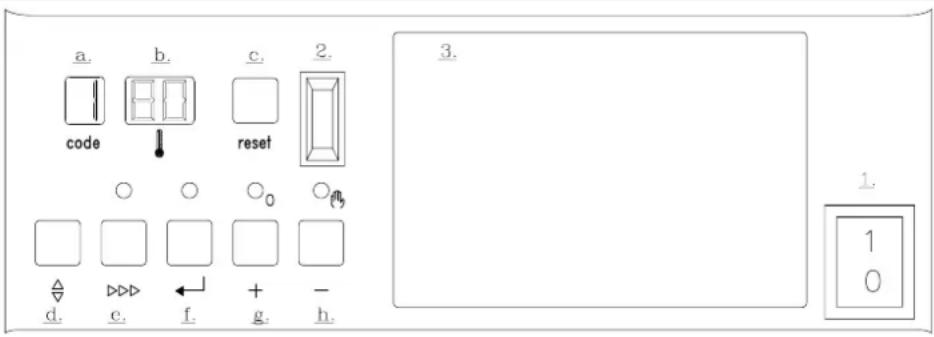
a. code b. 80 reset c. 2. O O O₀ Oₕ Δ d. e. f. + g. - h. 3. 1. 1 0fig. 03 Instrument panel
00.31H.79.00010
The Remeha Gas 310 ECO boiler is supplied with an instrument panel. The Remeha 610 ECO is supplied with an instrument panel on each boiler module. This instrument panel is provided with an intelligent, advanced boiler control ('abc®'). Using the keys, different menus can be accessed, various values can be read and settings made. The instrument panel consists of the following components:
- On/off switch.
- PC-connection.
- Facility for incorporating a rematiceather compensator.
A. Code-display, indication of operating, setting, read-out, shut-off, test and failure codes.
B. ⏻-display, indication of temperatures, settings and shut-off and lock-out codes.
C. Reset-key, to reset the boiler after a lockout.
D. -key, key to select the required mode (mode-key).
E. ▷▶▶-key, key to select the required program within the selected mode (step-key).
F. ←-key, key to save the settings (store-key).
G. [+] -key, to select a higher setting.
H. [-]-key, to select a lower setting / switch function: manual override (hand/auto).
The user has a number of setting options, which can be evoked via the 12 -key. The desired code (see next text block) can be chosen by pressing the 12 -key until the digit ! (with dot) appears in the code-display. Now choose the desired code by pressing the -key. Next, set the required value in the ! -display, using the [+] - and [-] -keys. Press the -key to store the new value (value will flash twice).
To gain access to the service level, the control system requires an input code.
The boiler control has the following pre-set values:
Flow temperature : 90°C
- Pump run on time : 3 minutes
R Boiler control : 31 - modulating on flow
temperature without booster function.
Settings should only be adjusted after consulting
your installer (or in case of emergency), see section
'Setting mode at user level' in our Technical Information.
Code reports in code-display
☐ - only digit or letter; operating mode
- digit or letter with dot; setting mode
- digit or letter with flashing dot; read-out mode
b - letter b; shut-off mode (temporary, no boiler failure)
- digit flashes;failure mode
Operating mode (X □□)
During operation the code window shows the status (operation) of the boiler, whereas the ⏻ window indicates the measured boiler flow temperature.
| Code | Description |
| Stand-by; no heat demand | |
| Vent (pre-ventilation time 12 seconds, post ventilation time 3 seconds) | |
| Ignite | |
| The boiler is firing (flame detection) | |
| Waiting; checking that there is sufficient air transport using fan and air pressure differential switch (LDS) | |
| Controls stop (burner off + post ventilation) | |
| Run-on time, pump and fan | |
| Shutdown mode | |
| Gas leakage control |
COMMISSIONING THE BOILER
- First follow the guidelines that your installer supplied for the entire installation. If not available: follow the instructions below.
- Check the water pressure in the installation (min. 0.8 bar). Fill up when necessary.
- Open the main gas cock.
- Put the boiler control to heat demand.
- Start the circulation pump.
- Switch on the electrical supply to the boiler and the on/off switch on the instrument panel.
- The following operation course shall successively appear on the code-display:
5 = Waiting mode; the fan runs and the boiler waits until sufficient air transport is established (air pressure switch open or closed).
I = Pre-purging.
2 = Ignition of the gas/air mixture.
3 = The burner is firing.
The boiler now operates.
If this fails to work, switch the boiler to manual operation (see Chapter "Operation" from the Technical Information), set the flow temperature to the desired value and contact your installer.
- First follow the guidelines that your installer supplied for the entire installation. If not available: follow the instructions below.
- Turn off the boiler control.
- Close the main gas cock.
- Switch off the electrical supply.
Attention! Think of the risk of freezing!
If temperatures are low, it is recommended to run the central heating installation at a reduced temperature to avoid freezing up.
VENTING OF THE INSTALLATION
- Put the boiler control to heat demand.
- Open all the radiator valves.
- Run the installation up to about 80^ C.
- Switch off the electrical supply to the boiler.
- Wait for approximately 10 minutes.
- First vent the installation on all the vent points (boiler, radiators, etc.).
- Check the water pressure and, if necessary, fill up to design system pressure; entirely fill the filling hose before connecting it to the installation.
8. Put the boiler into service again.
Repeat venting procedure, if necessary.
Attention!
A poorly vented installation may cause water flow problems and air noise in the boiler, the pipework and the radiators.
TROUBLE SHOOTING
Before calling in the installing engineer, first check if:
- The gas cock is open
- The maximum operating temperature setting is high enough
- The boiler control has been correctly set
- The main switch is on
- A sufficient water flow is possible (the radiator valves are entirely opened)
- The water pressure is sufficient (> 0.8 bar).
Note down the failure message before resetting
(3 digits, blinking and dots included). Reset the failure by pressing the reset-key on the instrument panel. If the boiler failure is immediately repeated, contact the installing engineer, stating the failure message.
Attention!
Do not forget that your central heating installation needs servicing once a year.
On gas smell: close main gas cock and warn gas company or installer.
GENERALITES
text_image
Technical diagram of a mechanical device with numbered components and labeled parts in Chinesefig. 01 Coupe Remeha Gas 310 ECO 00.31H.79.00002
text_image
Technical diagram of an electrical equipment cabinet with numbered components and piping connectionsfig. 02 Vue arrière Remeha Gas 610 ECO 00.61H.00002