Celcia MC4 - Thermostat Remeha - Free user manual and instructions
Find the device manual for free Celcia MC4 Remeha in PDF.
| Product type | Cascade controller for Remeha boilers |
| Brand | Remeha |
| Model | Celcia MC4 |
| Dimensions (W x H x D) | 205 x 163 x 53 mm |
| Weight | Approximately 430 g |
| Power supply | 230 VAC / 50 Hz |
| Power consumption | 4 VA (without circulator) |
| Number of boilers controlled | 1 to 4 in cascade |
| Communication with boilers | OpenTherm |
| Inputs | Outdoor temperature sensor (NTC, -20 to 40 °C), Flow temperature sensor (NTC, 0 to 100 °C) |
| Outputs | Pump (230 VAC, 2A max), Fault relay (dry contact, 230 VAC, 2A max) |
| Display and control | LED indicators (status, thermostat, boilers, sensors, pump, fault) and auto-configuration button |
| Operating temperature | 0 to 50 °C |
| Relative humidity | 10 to 90 % (non-condensing) |
| Mounting | Wall-mounted, with drilling template and fixings supplied |
| Maintenance and cleaning | No specific maintenance required. Clean with a dry cloth. Avoid water. |
| Safety | Follow electrical safety instructions (EN 60730-1). Disconnect before any intervention. |
| Spare parts and repairability | Contact Remeha after-sales service. Sensors and accessories are available. |
| General information | Installation and operation manual included. Compatible with Remeha OpenTherm boilers (except Selecta). |
Frequently Asked Questions - Celcia MC4 Remeha
User questions about Celcia MC4 Remeha
0 question about this device. Answer the ones you know or ask your own.
Ask a new question about this device
Download the instructions for your Thermostat in PDF format for free! Find your manual Celcia MC4 - Remeha and take your electronic device back in hand. On this page are published all the documents necessary for the use of your device. Celcia MC4 by Remeha.
USER MANUAL Celcia MC4 Remeha
INTRODUCTION
1 SAFETY
2 INSTALLATION
1.1 General safety 21
1.2 Safety during assembly and installation 21
2.1 Scale of delivery 21
2.2 Mounting and connecting the regulator 21
2.2.1 Mounting guidelines 21
2.2.2 Mounting the Celcia MC4 22
2.2.3 Guidelines for connecting the sensors and wiring the system components 22
2.2.4 Connecting the sensors and wiring the system components 22
2.2.5 Principle diagram of the connection of system components 24
2.2.6 Choice of boilers 24
2.3 Putting into Operation 24
2.3.1 Operation 24
2.3.2 Definition of LED indicators 25
2.3.3 Putting regulator into working order 26
2.3.4 Checking the working of the Celcia MC4 26
2.4 Normal start-up procedure 26
2.4.1 Adjusting the regulator according to the system 26
2.4.2 Removing a boiler from the cascade 27
3 FAULTS
3.1 General 28
3.1.1 Failure signals via the LED indicators. 28
3.1.2 Failure signals via the Celcia 20 display 29
3.1.3 Failure signals via the failure relay 29
4 REGULATIONS 30
4.1 Standards 30
4.2 Remeha factory test 30
1.3 Additional guidelines 30
5 TECHNICAL SPECIFICATIONS AND WORKING PRINCIPLE 31
5.1 Technical data 31
5.1.1 Regulator construction 31
5.1.2 Working principle 31
5.1.3 Switching method 32
FR
PREFACE 34
1 SECURITE 35
2 INSTALLATION 35
In combination with a Celcia 20, the Remeha Celcia MC4 is a regulator for the modulating control of between 1 and 4 Remeha boilers in cascade.
This Installation- and Users manual is intended for installers and end users. The document contains important information about the regulator, preparation for assembly and installation, operation, inspection, maintenance, technical specifications and the identification and elimination of errors.
In addition to the Installation- and Users manual, the Remeha Celcia MC4 documentation consists of:
The Product Data Sheet, for those interested in technical and/or commercial aspects.
For further useful information see the Remeha internet site: www.remeha.com

- Please read this manual carefully before mounting and connecting the regulator, or putting it into operation; familiarize yourself with how the regulator works and how to use it, and follow the instructions exactly.
- We will not be liable for any damage resulting from the instructions in this documentation not being followed.
We continually seek to improve our products. The data published in this manual are based on the most recent information and are issued subject to later modifications. We reserve the right to modify the construction and/or finish of our products at any given time without any obligation to adapt earlier supplies accordingly.
Please do not hesitate to contact us if you have any suggestions to improve this documentation.
1 SAFETY
1.1 General safety
The following pictograms are used in this Installation- and Users manual to specifically draw certain points to your attention:
Tip

Useful tip or practical advice.
Indication

Important instruction in carrying out a particular operation.
Warning

Possible danger of personal injury or material damage to the regulator, building or environment.
Danger

Serious personal injury can occur because of risk of electric shocks.
1.2 Safety during assembly and installation
Observe the appropriate safety measures, as given in these instructions.
2 INSTALLATION
LT.AL.REM.000.002
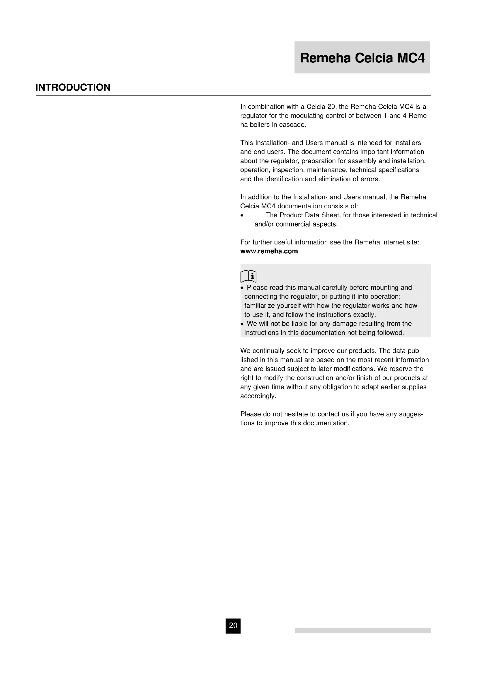
2.1 Scale of delivery
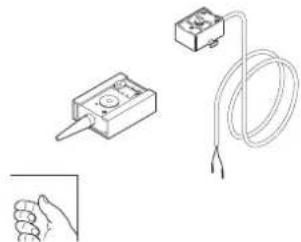
The standard delivery of the Remeha Celcia MC4 includes:
- the Remeha Celcia MC4 cascade regulator;
- earthed plug;
- drilling template and fixtures for wall mounting;
- strain relief clips and screws;
- ZAF 200 = outside temperature sensor;
- ZVF 210 = system flow temperature sensor;
- Installation- and Users manual.
2.2 Mounting and connecting the regulator
This chapter includes the guidelines and instructions for the connection of the regulator, sensors, thermostats, regulators, pump outlet and failure relay.
2.2.1 Mounting guidelines
- Mount the regulator in an easily accessible position at eye level at eye level.
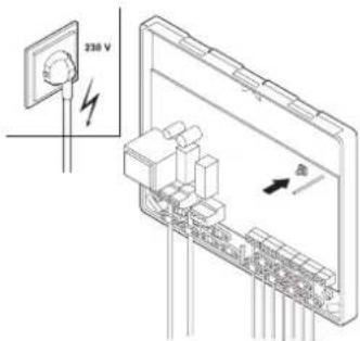
Make sure it is near an earthed 230 VAC / 50HZ mains connection. The mains lead supplied is 1.5m long. - Ensure that the cable connection between the Celcia MC4 and other system components is as short as possible and preferably not close to any other cables.
LT.AL.REM.000.004
LT.AL.REM.000.005 LT.AL.REM.000.006
LT AL,REM.000.007 LT AL,REM.000.008
LT AL REM.000.009 LT AL REM.000.010
A
Note the requirements regarding ambient temperature and the permissible relative humidity.
- Make sure the regulator cannot get splashed.
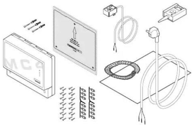
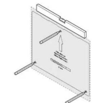
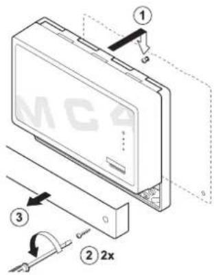
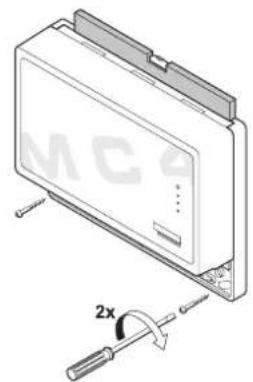
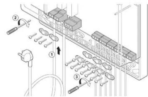
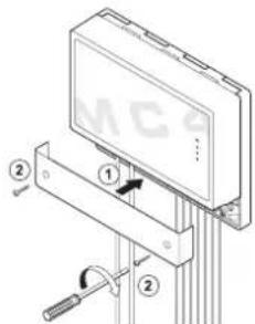
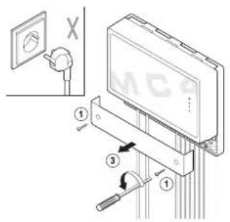
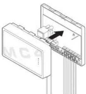
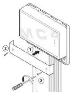
2.2.2 Mounting the Celcia MC4
The regulator is mounted using three screws. The top screw is to hang the regulator on and cannot be tightened once the regulator has been mounted. The bottom screws (behind the small cover) are to hold it firmly in place.
Mount the regulator as follows:
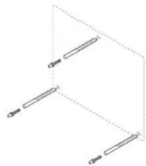
- Determine the position of the regulator and press the drilling template against the wall.
- Drill the three holes (Ø 5 mm) as indicated by the template.
- Insert the plugs.
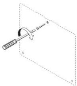
- Screw the top screw into the plug and mount the regulator without any play.
- Remove the small cover from the regulator to make the lower slots accessible.
- Screw the bottom two screws into the plugs.
- Straighten the regulator and tighten these two screws.
- Replace the cover.
2.2.3 Guidelines for connecting the sensors and wiring the system components
- Mount the regulator as close as possible to the system components to be controlled (check maximum cable lengths for OpenTherm connections and sensors)
An earth terminal has been fitted next to the connection for the mains lead. Always connect this in order to comply with the safety regulations.
Always connect the mains supply to an earthed wall socket. - Use double insulated wiring for the exit relays that switch a power supply with no earth connection..
- Fit a strain relief to all cable connections.
#
Looping the supply voltage and/or earth to e.g. a pump, is not allowed.
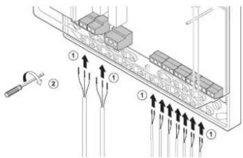
2.2.4 Connecting the sensors and wiring the system components
Connect temperature sensors, thermostats, boilers and other wiring as follows:
7
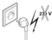
Always switch the mains voltage off before assembling any electrical components,
R remeha
LT.AL,REM.000.013
LT.AL.REM.000.011
LT.AL.REM.000.014
LT.AL.REM.000.015
LT.AL.REM.000.016
LT AL REM.000.017
LTLALREM000.018LTALREM000.019
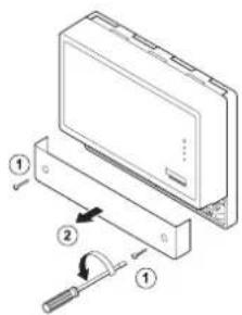
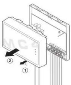
- Remove the small cover.
- Fit the required temperature sensors and other system components.
- Lead the cables to the regulator and connect them according the principle diagram.
- Connect the mains lead.
- Fit the strain relief clips and check that all the cables are properly clamped.
- Replace the cover.
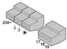
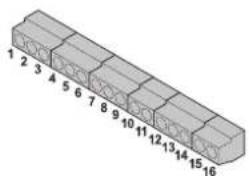
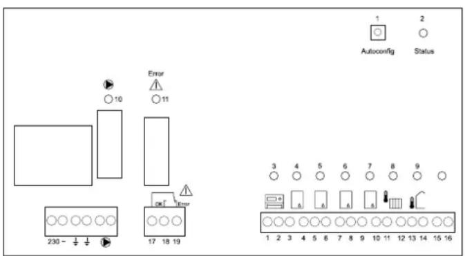
table 01 I/O connections Celcia MC4
| Terminals on the regulator | Connecting system components |
| 230 ~ Mains voltage 230 VAC / 50 Hz | |
| Earth terminals | |
| Pump connection (U) | |
| 1 and 2 Celcia 15 or 20 regulator | |
| 3 and 4 Boiler connction (OpenTherm) | 1) |
| 5 and 6 Boiler connction (OpenTherm) | 1) |
| 7 and 8 Boiler connction (OpenTherm) | 1) |
| 9 and 10 Boiler connction (OpenTherm) | 1) |
| 11 and 12 System flow temperature sensor (Bv) | |
| 13 and 14 Outside temperature sensor (Ba) | |
| 15 and 16 No function | |
| 17 and 18 Potential free contacts | 2) |
| 17 and 19 Potential free contacts | 3) |
1) Must be connected to the boiler's OpenTherm terminals
2) Operation signal; contacts 17 and 18 are closed if everything is in order (the boilers do not need to burn) and open with a fault (internal, boiler fault, communication fault or wiring fault)
3) Failure signal; contacts 17 and 19 are closed if a fault occurs (internal, boiler fault, communication fault or wiring fault, voltage failure) and open if everything is in order.

No sequential regulators are to be coupled to the Celcia MC4, as in a mixing group, swimming pool or boiler regulation, for example. The tap water system is regulated via the control unit of one of the boilers.
Mounting the outside temperature sensor:
Mount the outside sensor, protected against direct sunlight, on the north or northwest side of the building, at a height of 2.5 metres min. from ground level. Do not mount the outside temperature sensor close to windows, doors, ventilation grids or exhaust covers, etc.
LT.AL.REM.000.028
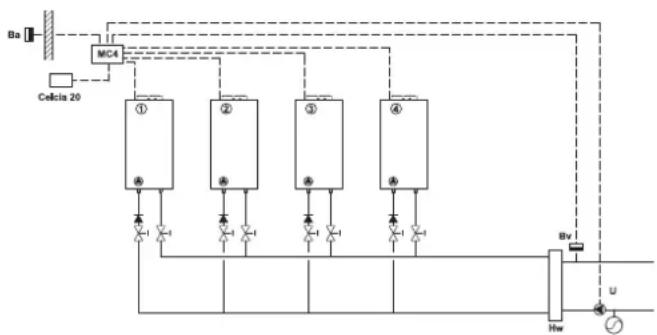
2.2.5 Principle diagram of the connection of system components
Ba = Outside temperature sensor
Bv = System flow temperature sensor
U = System pump
Hw = Low loss header
2.2.6 Choice of boilers
All boilers in the cascade system should have OpenTherm communication.

For correct cascade regulation, the ratio between the powers of the largest and smallest boilers may not be more than 2.5.
A good combination is, for example: 40kW80kW + 80kW (80 : 40 = 2 is < 2.5; i.e. good)
A bad combination is, for example: 40kW + 40kW + 120kW (120:40 = 3 is >2.5 i.e. bad
2.3 Putting into Operation
2.3.1 Operation
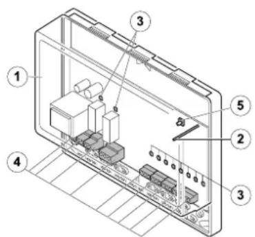
The operation of the Celcia MC4 contains one function key for the automatic configuration and LED indications.
1 = 'autoconfig' button
2 = status LED
3 = thermostatLED
4-7 = boiler LEDs
8 = system flow temperature sensor LED
9 = outside temperature sensor LED
10 = pumpLED
11 = failure relay LED
LT.AL.REM.000.016
2.3.2 Definition of LED indicators
The following LED indicators can light up on the Celcia MC4 control panel:
table 02 Definition of LED indicators
| LED indicator Colour | Indication and definition | |
| 2 = status LED green | - not lit, no mains voltage - continuously lit, Celcia MC4 is working normally - flashing slowly; boiler or communication fault - flashing quickly; Celcia MC4 is configuring | |
| 3 = thermostat LED | yellow | - lit continuously; Celcia MC4 is connected to Celcia 15 or 20 regulator or on/off thermostat is closed - not lit; no Celcia 15 or 20 regulator connected or on/off thermostat is open - flashing slowly; Celcia MC4 has no connection with OpenTherm thermostat - flashing quickly; Celcia MC4 is configuring |
| 4 - 7 = boiler LEDs | yellow | - lit continuously; if the appropriate boiler is connected - not lit; if the appropriate boiler is not connected - flashing slowly; communication fault or boiler is not suited for Celcia MC4 control (only with connected boiler) - flashing quickly; Celcia MC4 is configuring |
| 8 = system flow temperature sensor LED | yellow | - lit continuously; if the appropriate sensor is connected - not lit; if the appropriate sensor has not been found - flashing slowly; sensor measuring value beyond the limits - flashing quickly; Celcia MC4 is configuring |
| 9 = outside temperature sensor LED | yellow | - lit continuously; if the appropriate sensor is connected - not lit; if the appropriate sensor has not been found - flashing slowly; sensor measuring value beyond the limits - flashing quickly; Celcia MC4 is configuring |
| 10 = pump LED yellow | - lit continuously; pump is switched on - not lit; pump is switched off - flashing quickly; Celcia MC4 is configuring | |
| 11 = failure relay LED | yellow | - lit continuously; an internal failure has occurred, boiler, communication or wiring fault - not lit; everything working properly - flashing quickly; Celcia MC4 is configuring |
Remeha Celcia MC4
LT AL REM.000.022 LT AL REM.000.023
LT.AL.REM.000.024 LT.AL.REM.000.025
LT.AL.REM.000.026 LT.AL.REM.000.027
2.3.3 Putting regulator into working order
This section details the procedure for putting the regulator into working order. What to do:
- Leave the regulator unplugged.
- Remove the small cover.
- Check that all the connections, including earth connections, have been made correctly.
- Remove the large cover.
- Switch all system components on.
- Insert the Celcia MC4 plug in the socket.
- Press the 'autoconfig' key until all LEDs flash quickly; all installation components are detected.
- The configuration will be stored in the regulator memory within 10 seconds.
- Now the status LED will stay on (unless there is a fault) and the Celcia MC4 is ready for operation.
2.3.4 Checking the working of the Celcia MC4
The working of the regulator can be checked by connecting the OpenTherm connection to terminals 1 and 2. The Celcia MC4 will control the boilers at minimum load. After 1 minute, all boilers will simultaneously be set to full load for 10 minutes. The system flow temperature can then rise to the maximum flow temperature of the boilers connected.
2.4 Normal start-up procedure
The Celcia MC4 receives the required flow temperature from the OpenTherm thermostat and calculates the required capacity on the basis of the difference between the measured and the required flow temperatures. The Celcia MC4 distributes this capacity over the connected boilers, according to a set switching method.
If an outdoor sensor (Ba) is connected the Celcia MC4 will transmit the outside temperature to the connected OpenTherm thermostat, enabling weather-dependent control. The Celcia MC4 has no internal heat curve.

If the Celcia 20 regulator is being used as a weather-dependent regulator, the outdoor sensor (Ba) is connected to terminals 13 and 14 of the Celcia MC4.
2.4.1 Adjusting the regulator according to the system
The Celcia MC4 can be adjusted to a new system, literally 'at the touch of a button'. If the current system has been configured with three boilers and is to be extended with a fourth, complete the hydraulic and electrical connections and then press the autoconfig' button for about 3 seconds. The regulator will now distribute the required output over four boilers instead of three.
2.4.2 Removing a boiler from the cascade
Reducing the system, e.g. from four boilers to two, is just as simple. Disconnect the boiler connections (unplug them) and then press the autoconfig' button for about 3 seconds. The regulator will now distribute the required output over two boilers instead of four.

Other newly added components (OpenTherm regulators or temperature sensors) are also added to the configuration automatically.
3.1 General
If any of the connected boilers goes into fault mode, or is heating tap water, the Celcia MC4 will automatically switch the following boiler on.
The LED indicators on the Celcia MC4 also serve as fault indicator. If the regulator is controlled via the Celcia 15 or 20, the failure signal will be displayed on the Celcia 15 or 20.
3.1.1 Failure signals via the LED indicators.
The LED indicators on the Celcia MC4 display failures as follows:
table 03 LED failure indications
| LED indicator flashing slowly | Indication and definition | Check / solution |
| status LED | Celcia MC4 internal failure, sensor, boiler or communication fault. | First check the other LEDs under the large cover and resolve the failure. |
| thermostat LED | Celcia MC4 is no longer connected to the OpenTherm thermostat. | Check the wiring to and from the thermostat, or has the thermostat been removed? |
| boiler LEDs | Celcia MC4 is no longer connected to the boiler, or the boiler is in failure mode. | Is the boiler in failure mode or switched off? Check the OpenTherm connection. |
| system flow temperature sensor LED | Sensor measuring value no longer within the limits. | Check the wiring. Measure the sensor resistance value, see table 04. |
| outside temperature sensor LED | Sensor measuring value no longer within the limits. | Check the wiring. Measure the sensor resistance value, see table 04. |
Table 04 Sensor resistance values
| Temperature [℃] | Resistance System flow temperature sensor or Outside temperature sensor [Ohm] |
| -10 27.649 | |
| -5 21.034 | |
| 0 16.325 | |
| 5 13.023 | |
| 10 9.952 | |
| 20 6.247 | |
| 25 5.000 | |
| 40 2.662 | |
| 60 1.244 | |
| 80 628 | |
| 100 339 |
3.1.2 Failure signals via the Celcia 20 display
If the regulator is controlled via the Celcia 20, the code of any failure occurring can be read from the Celcia 20 display. Any boiler failures are also transmitted.
| Failure code Description | Check / solution | |
| 210 | The installation flow temperature is below 0°C or above 100°C. | Check if the common flow temperature sensor is properly connected. Measure the sensor resistance value, see table 04. |
| 211 | No communication between Celcia MC4 and one or more boilers. | Check the wiring. Is one of the boilers off? |
| 212 Boiler is not suited | for Celcia MC4 control. Contact Remeha. | |
| 213 | Outside temperature sensor measuring value no longer within the limits. | Check the wiring. Measure the sensor resistance value, see table 04. |
| Other numbers | See the manual of the Celcia 20, the boiler or of other connected components. |
table 05 Failure signals via the Celcia 20 display

The Celcia 15 regulator can only display failure codes up till 99. In case a higher code occurs, a flashing will be displayed.
3.1.3 Failure signals via the failure relay
If a failure occurs or if there is a failure in the power supply to the Celcia MC4, connect the fault contact between terminals 17 and 19 (with a 1 minute time delay and directly in case of failure in the power supply). This contact can be used to control such things as a light, a buzzer or a failure signal.
4.1 Standards
The installer is responsible for ensuring that the installation complies with the current (safety) regulations as laid down in
- This Installation- and Users manual any other relevant Remeha documentation;
- safety provisions for low-voltage installations.
4.2 Remeha factory test
Each Remeha Celcia MC4 regulator is a precision instrument and is programmed and tested before it leaves the factory.
4.3 Additional guidelines
It applies for all regulations and guidelines mentioned in this Installation- and Users manual that any additions or new regulations and guidelines at the time of installation will also apply.
5 TECHNICAL SPECIFICATIONS AND WORKING PRINCIPLE
5.1 Technical data
Table 06 Summary of technical data
| Remeha Celcia MC 4 | ||
| General | ||
| Dimensions (w x h x d) mm 205 x 163 x 53 | ||
| Weight g approx. 430 | ||
| Nominal supply voltage VAC / Hz 230 / 50 | ||
| Rated input VA 4 | ||
| Safety requirements (household use) - EN 60730-1 | ||
| EMC interference suppression (immunity) - EN 61000-6-2 | ||
| EMC interference suppression (emission) - EN 61000-6-3 | ||
| Maximum ambient temperature (storage and transport) | °C | - 20 - 70 |
| Maximum ambient temperature (operational situation) | °C | 0 - 50 |
| Maximum relative humidity (non-condensation) | % | 10 - 90 |
| Inputs | ||
| Outside temperature sensor1) | - | NTC sensor (range 10 - 40 °C) |
| System flow temperature sensor2) | - | NTC sensor (range 10 - 100 °C) |
| Outputs | ||
| Pump output (live, make contact*) | - | switching power 230 VAC, 2A max. |
| Failure relay output (potential free switching contact) | - | switching power 230 VAC, 2A max. |
| OpenTherm connections | ||
| OpenTherm boiler connections3) | quantity | 4 |
| OpenTherm thermostat connection | quantity | 1 |
LT.AL.REM.000.021
^* Protect this output externally
1) Maximum cable length = 100M (2× 10)
2) Maximum cable length = 25M (2 x 10 Ω)
3) Maximum cable length = 50M (2× 5)
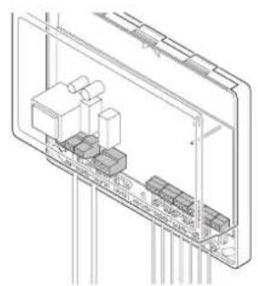
5.1.1 Regulator construction
- Cover
2.StatusLED - LEDs for failure analysis
- Connection terminals
- Configuration button
5.1.2 Working principle
The Celcia MC4 is a regulator for the modulating control of between 1 and 4 Remeha boilers in cascade, according to the flow temperature demanded (via the OpenTherm input). With the exception of the Remeha Selecta, all OpenTherm boilers in the Remeha range can be controlled by the Celcia MC4. Please contact our Sales Support department if you wish to use the Celcia MC4 in combination with older boiler types or the Gas 210 ECO and Gas 310 ECO. The Celcia MC4 has a failure relay (the contact switches in the event of a power failure and/or a failure in the Celcia MC4 or one of the boilers) and also regulates the system pump. The (internal) boiler pumps are controlled by the boiler control units.
Required output
Data are exchanged between the regulator and the boilers via the OpenTherm connections. The Celcia MC4 receives the flow temperature demand from an Celcia 15 or 20 regulator. In the case of a room thermostat the flow temperature demand is determined on the basis of the ambient temperature. In the case of a weather-dependent regulator the flow temperature demand is determined on the basis of the heat curve and the outside temperature. The Celcia MC4 transmits the measured outside temperature to the controlling Celcia 15 or 20 regulator. The required output is determined according to the difference between the measured flow temperature and the flow temperature demanded.
The Celcia MC4 distributes this capacity over the (OpenTherm controlled) boilers connected. A set switching method determines the distribution.
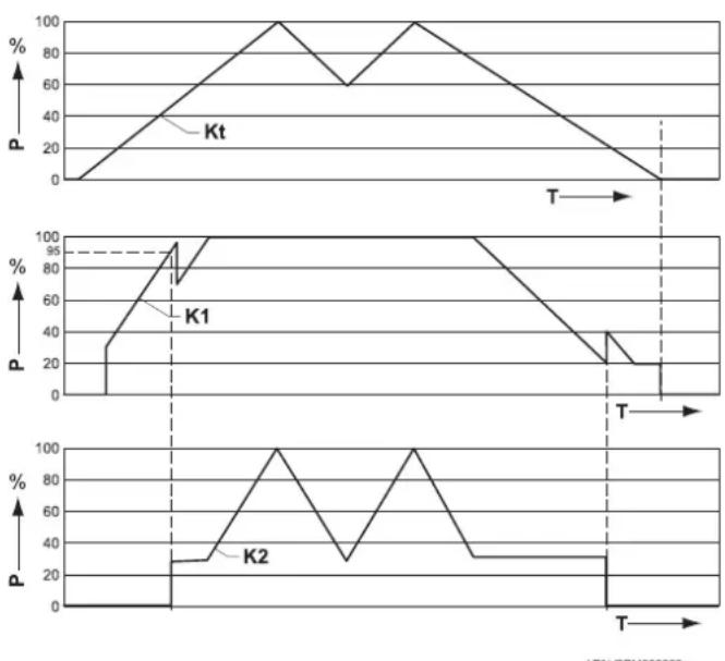
5.1.3 Switching method
By way of a set switching method the Celcia MC4 determines when the boiler is switched on and the required output. The regulator ensures that the boilers are equally loaded by recording the number of hours each boiler is in operation. The switching method is such that as the required output increases, the regulator will wait as long as possible (the first boiler will then operate at 95% of its own capacity) before switching the second boiler on (after a time delay of 5 minutes). As the required output decreases, the regulator will wait as long as possible before switching the first boiler off.
LTLAL.REM.000.029
Operating sequence
The sequence in which the boilers are to be switched on and off, is set during the configuration. It is determined on the basis on the number of operating hours. The boiler with the least operating hours is switched on first and the boiler with the most operating hours is switched on last. The boilers are switched off in reverse order, so the boiler that was switched on first is switched off last.
P = required output
Kt = total output
K1 = outputboiler1
- This is a global description of the operation. The effect of part load time, individual power differences etc. are not shown in this graph.