TFPF03MC - Thermostat Seitron - Free user manual and instructions
Find the device manual for free TFPF03MC Seitron in PDF.
Document temporarily unavailable
The manual is currently being transferred to our new server. It will be accessible again in a few hours. Thank you for your patience.
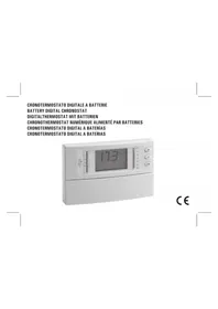
| Product type | Digital thermostat for fan coil units |
| Brand | Seitron |
| Model | TFPF03MC |
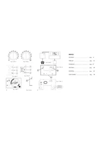
| Dimensions (W x H x D) | 129 x 96 x 37 mm |
| Weight | ~265 g |
| Power supply | 230 V~ or 24 V~ (selectable via jumper JP1/JP2) |
| Power consumption | 1.2 VA |
| Operating temperature | 0 °C to 40 °C |
| Storage temperature | -10 °C to +50 °C |
| Operating humidity | 20 % to 80 % RH (non-condensing) |
| Protection rating | IP20 |
| Housing material | Self-extinguishing ABS V0 |
| Housing color | Dome: safety white; base and keys: light gray |
| Temperature sensor type | NTC 4.7 kΩ ±2% at 25 °C (internal or external optional) |
| Ambient temperature accuracy | ±1 °C |
| Ambient temperature resolution | 0.1 °C |
| Control range | 5 °C to 35 °C (configurable) |
| Display range | 0 °C to 40 °C |
| Differential | 0.2 °C to 1.0 °C (adjustable) |
| Fan outputs | 3 voltage-free relays (terminals 1-4): 3 A @ 230 V~, cos φ=1 |
| Valve outputs | Terminals 8-11: 0.3 A @ 230 V~, max 10 VA (inductive load) |
| Main functions | 3-speed fan control, heating/cooling mode, automatic changeover, Economy function, antifreeze, minimum thermostat, dirty filter alert |
| Supported installation types | 2-pipe, 4-pipe, integral electric heater, heat pump |
| Maintenance and cleaning | Periodic cleaning of the fan coil filter; the unit signals via the display "FIL-TER"; reset by holding the speed key for 10 seconds |
| Safety | Power supply via omnipolar switch (contact gap ≥3 mm); installation by qualified personnel; double insulation of accessible probes |
| Spare parts and repairability | NTC 4.7 kΩ sensor; repairs reserved for a professional |
| General information | Compliant with European directive 1999/44/EC; warranty available on request |
Frequently Asked Questions - TFPF03MC Seitron
User questions about TFPF03MC Seitron
0 question about this device. Answer the ones you know or ask your own.
Ask a new question about this device
Download the instructions for your Thermostat in PDF format for free! Find your manual TFPF03MC - Seitron and take your electronic device back in hand. On this page are published all the documents necessary for the use of your device. TFPF03MC by Seitron.