TCD01B - Thermostat Seitron - Free user manual and instructions
Find the device manual for free TCD01B Seitron in PDF.
| Product type | Daily electronic chronothermostat |
| Dimensions (W x H x D) | 133 × 87 × 32 mm |
| Weight | Approximately 218 g |
| Power supply | 2 alkaline batteries 1.5 V type AA |
| Battery life | More than one year |
| Comfort temperature range | 10 °C to 30 °C |
| Reduced temperature range | 10 °C to 30 °C |
| Main functions | Time programming by jumpers, heating/cooling modes, frost protection function, backlighting, internal sensor and optional remote probe |
| Maintenance and cleaning | Clean with a dry cloth; do not use solvents |
| Safety | Installation by qualified personnel; cut off power before connection; use an omnipolar switch |
| Spare parts and repairability | Type AA batteries; NTC 10 kΩ ±1% @ 25 °C remote probe (optional); fixing screws |
| General information | Warranty according to European directive 1999/44/EC |
Frequently Asked Questions - TCD01B Seitron
User questions about TCD01B Seitron
0 question about this device. Answer the ones you know or ask your own.
Ask a new question about this device
Download the instructions for your Thermostat in PDF format for free! Find your manual TCD01B - Seitron and take your electronic device back in hand. On this page are published all the documents necessary for the use of your device. TCD01B by Seitron.
USER MANUAL TCD01B Seitron
'0FS2' IMPOSTAZIONE OFFSET DELLA SONDA REMOTA
This device is an electronic daily chronostat with an ample backlit display for showing the room temperature reading or current time, as desired.
The room temperature can be set in the Heating or Cooling mode on two different levels: Comfort and Economy.
In addition, the device offers the option of setting the Antifreeze temperature and adjusting the Offset value on the internal sensor.
INSTALLATION
The device is designed to be installed in a standard recess (or wall) mounted junction box with two or three modules or else directly on the wall using the screw anchors provided.
To install the device carry out the following steps:
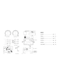
- Release the wall plate fitted under the base of the timer thermostat as shown in Fig. 2.
Fix the plate directly to the wall or a 3-module flush connection box using the two screw fastening holes with centres spaced 60~mm or 85~mm apart (Fig. 3), taking care to thread the wires through the slot as shown in Fig. 3. - Make the electrical connections following the connection layout shown in Fig. 4.
- Bring the timer thermostat near the wall plate, first matching up the teeth on the base with the holes in the plate, and then pressing downward on the device until the plastic teeth snap into place; then fix the chronostat body to the wall mount plate through the two screws supplied which must be mounted in the battery holder (Fig. 3).
- Insert the batteries in the battery compartment (M in Fig. 1); see
paragraph 'HOW TO INSERT/REPLACE THE BATTERIES'.
The chronostat must be positioned about 1.5m above floor level, away from sources of heat, doors and windows.
STARTING
When operating the device for the first time:
Fit the batteries into the compartment provided, observing proper polarity (Fig. 1). Reset the device by inserting a pointed implement through the hole provided (L on Fig. 1); DO NOT USE NEEDLES.
There are three control buttons beneath the lower cover 3:
'OK': Programming/Time/Confirm (I on Fig. 1);
^ : Forward (G on Fig. 1);
Back (H on Fig. 1);
Setting the current time
To set the timer thermostat clock carry out the following steps:
1. Open the cover of the battery compartment.
2. Press the 'OK' button for at least 2 seconds.
3. Set the hour using buttons and .
4. Confirm with 'OK'.
5. Set the minutes using buttons and
6. Confirm with 'OK'.
Setting the Heating / Cooling modes
Pressing button for at least 4 seconds will activate the Heating function and the symbol will appear flashing on the display.
Pressing button for at least 4 seconds will instead activate the 'Cooling' function and the symbol will appear flashing on the display.
Setting the Comfort and Economy modes
The timer thermostat has 24 switches (A on Fig. 1), situated alongside the display, for programming operation in the 'Comfort' or 'Economy' modes at different times of the day.
When you want the timer thermostat to operate in the comfort mode, for example during the daytime, move all the switches corresponding to the desired time interval over to the right.
If you want the timer thermostat to operate in the economy mode, for example during the nighttime, just move all of the switches corresponding to the desired time interval over to the left.
In this case it is sufficient to remember the following rule:
Switches positioned to the right: The comfort setting is enabled in the automatic operating mode.
Switches positioned to the left: The economy/night setting is enabled automatic operating mode.
Each switch corresponds to the interval falling between the times printed above and below the switch itself.
For example, note that the time interval from 00 to 05 is controlled by a single switch, whereas from 05 to 09 in the morning settings can be made at half-hour intervals. For the rest of the day, the selectable time intervals are one hour each (A on Fig. 1).
The Comfort temperature is set by means of knob ' (Sun), whereas the Economy temperature is set by means of knob ^ (Moon).
Normally, in order to have a reduced temperature at nighttime, knob 'C' will be set on a lower value than knob 'O'.
SETTING THE USER PARAMETERS
To enter the mode for setting the chronostat parameters, proceed
as follows:
- Press for more than 20 seconds the key 'A'; the display will show the first user parameter 'AFr'.
- Press the 'O' button repeatedly to scroll through the user parameters:
Antifreeze Setting AFr
Internal sensor Offset setting ' OFS1'
Remote sensor Offset setting ' OFS2'
Regulation sensor choice setting 'rEG' - Press the OK button to modify the selected parameter.
- Configure the data associated with each individual parameter as illustrated below.
- To exit the user parameter programming mode, press the OK button to confirm the changes made or else wait 10 seconds without pressing any button.
'AFr' ANTIFREEZE SETTING
The Antifreeze function allows you to select a minimum temperature to be maintained when the chronostat is off, so as to protect both the room and the equipment when the room temperature falls below the set value. The device leaves the factory with the Antifreeze function set on 3^ .
IMPORTANT: the function is active only when the device has been set in the heating mode.
To set the Antifreeze temperature, carry out the following steps:
- Select the parameter ' AFr' and press the 'OK' button.
- The display will show the previously set Antifreeze temperature.
- Press buttons ' and to change the setting (between OFF, 0.5^..25^ ); every change will be automatically
memorized.
- To exit press the OK button or else wait 10 seconds without pressing any button.
'0FS1' INTERNAL SENSOR OFFSET SETTING
With this parameter it is possible to correct the temperature reading of the internal sensor by ± 5^ in order to correct any systematic reading errors due to the positioning of the chronostat in areas unsuitable for measuring the room temperature. The device leaves the factory with the Offset set at 0.0^ .
To adjust the Offset value for the internal sensor, carry out the following steps: 1. Select the '0FS1' parameter and press the 'OK' button.
2. The display will show the previously set Offset temperature.
3. Press buttons and to modify the setting (range: -5.0°C .. +5.0°C); every change will be automatically stored in memory.
4. To exit press 'OK'
'0FS2'REMOTE SENSOR OFFSET SETTING
With this parameter it is possible to correct the temperature reading of the remote sensor by ± 5^ in order to correct any systematic reading errors due to the positioning of the remote sensor in areas unsuitable for measuring the room temperature. The device leaves the factory with the Offset set at 0.0^ .
To adjust the Offset value for the internal sensor, carry out the following steps: 1. Select the 'OFS2' parameter and press the 'OK' button.
2. The display will show the previously set Offset temperature.
3. Press buttons and to modify the setting (range: -5.0°C .. +5.0°C); every change will be automatically stored in memory.
4. To exit press 'OK'
'reg' REGULATION SENSOR CHOICE SETTING
This parameter sets whether the room temperature regulation is made based on the chronostat internal sensor or the remote sensor, wired at terminals 8 and 9.
For this parameter setting please find these directions:
- Select parameter 'rEG' then press key 'OK'
- The display shows 'In' or 'Out'.
- Press keys ' and ' to change the value (In: internal sensor -Out: remote sensor); each change is automatically stored in memory.
- Press key 'OK' to quit or wait 10 seconds without pressing any key.
WARNING: When the regulation is set according to the remote sensor 'Out' and in case this sensor is missing or broken, the temperature regulation will be performed according to the internal sensor, even if the parameter remains set on 'Out'.
SHUTDOWN - ANTI-FREEZE FUNCTION
To switch off the timer thermostat press 心 The display will show the word OFF' and the 心 symbol. If the timer thermostat was set in the heating mode, the antifreeze function will be enabled and the *symbol will appear on the display; in such a case the room temperature will be controlled according to the programmed antifreeze temperature set point.
MANUAL OPERATION
Pressing the ' 品 ' button will cause the ' 品 ' symbol to appear on the display and the timer thermostat will control the room temperature according to the current comfort mode setting selected by means of knob
' ', 24 hours a day, irrespective of the position of the dipswitches.
Toreverttooperationaccordingtothesetdailyprogram.press
' again.
TEMPERATURE / TIME DISPLAY
By repeatedly pressing the key 'the display cycles on showing the current time, the room temperature measured by the internal sensor, explained by the label IN, and the room temperature measured by thermotensor(ifwired)explained by the label
' OUT'. The values of temperature displayed are shown adjusted with the set Offset value.
WARNING
Labels 'IN' and 'OUT', according to the way they are displayed, assume the following different meaning:
IN: Fixed: The temperature shown on the display is the one measured by the internal sensor, yet the temperature regulation takes place according to the remote sensor.
Flashing: Both temperature shown and room temperature regulation refer to the internal sensor.
'OUT': Fixed: The temperature shown on the display is the one measured by the remote sensor, yet the temperature regulation takes place according to the internal sensor.
Flashing: Both temperature shown and room temperature regulation refer to the remote sensor.
In case the parameter 'rEG' is set on 'Out' but the remote sensor is not wired or is broken the display will show the words 'SEnS OPEN
' or 'SEnSHrt ' with the label ' OUT ' turned on.
IMPORTANT: In order to optimize battery life, the chronostat reads the room temperature every 3 minutes and activates or deactivates the relay accordingly.
BACKLIT DISPLAY
The display lights up any time a button is pressed.
The backlight automatically goes off 20 seconds after the last button was pressed.
CHANGING THE BATTERIES
The display constantly shows the battery charge status by means of the symbol. Batteries are fully charged if all three battery level indicators are lit up.
If the symbol is completely empty and ^* flashes, it means the batteries are low and need replacing.
To change the batteries proceed as follows:
- Open the battery compartment cover (Fig. 1).
- Remove the spent batteries, prying them out with a tool if necessary.
- Insert the new batteries, which must be alkaline 1.5V type AA.
- If necessary reset the device by means of the button as indicated in L on Fig. 1.
- Check that the time setting is correct, reprogram the time if necessary.
TECHNICAL CHARACTERISTICS
Power supply: 2 × 1.5V alkaline batteries (Type AA)
Battery life: >1 year
Backlight ON time: 20 seconds
Range of settings: comfort: 10^ .. 30^
economy: 10^ 30^
Differential: 0.2^ (asymmetrical)
Antifreeze: 0.0^ ..25.0°C. (Default 3.0°C)
Offset internal sensor: ± 5.0^ . (Default 0.0^ )
Offset remote probe: ± 5.0°C. (Default 0.0°C)
Sensor type: NTC 10K Ohm @ 25^ (Internal)
Remote probe type (optional): NTC 10K Ohm ±1% @ 25°C
Precision: ±1.0°C
Resolution: 0.1^ (0.0^..50.0^)
0.2°C (-9.9°C ... -0.1°C)
Contact capacity: 5(1)A @ 250V ~ SPDT
Protection rating: IP 30
Insulation Class: II (

Number of manual cycles: 1.000
Number of automatic cycles: 100.000
Type of action: 1CU
Tracking Index: PTI 175
Pollution situation: 2 (standard)
Impulse voltage rating:
Operating temp.: 0^ C + 40^ C
Storage temperature: -10°C..+50°C
Humidity limits: 20% .. 80% RH non-condensing
Enclosure: Material: ABS V0 self-extinguishing
Colour: Cover: Signal white (RAL 9003)
Base:Anthracite grey (RAL 7016)
Dimensions: 133 × 87 × 32 mm . (W × H × D)
Weight: ~ 218 gr.
EMC-LVD normative references:CEI-EN-60730-1 (2002)
CEI-EN-60730-2-7 (1998)
CEI-EN-60730-2-9 (1997)
WARNING
- To adjust properly room temperature, install the chronostat about 1.5m above floor level and far from heat sources, airstreams or particularly cold walls (thermal bridges).
In order to grant the electrical safety, it is mandatory to screw the chronostat body to the wall mount plate through the two screws supplied which must be mounted in the battery holder. - The appliance must be wired to the electric mains through a switch capable of disconnecting all poles in compliance with the current safety standards and with a contact separation of at least 3mm in all poles.
- Installation and electrical wirings of this appliance must be made by qualified technicians and in compliance with the current standards.
- Before wiring the appliance be sure to turn the mains power off.
WARRANTY
In the view of a constant development of their products, the manufacturer reserves the right for changing technical data and features without prior notice. The consumer is guaranteed against any lack of conformity according to the European Directive 1999/44/ EC as well as to the manufacturer's document about the warranty policy. The full text of warranty is available on request from the seller.
ALLGEMEINES
NTC 10K Ohm ± 1% @ 25°C
Fernuhlertype (optional): NTC 10K Ohm ±1% @ 25°C
Genauigkeit: ± 1°C
Resolution: 0.1^(0.0^..50^)
0.2°C (-9,9°C ... -0,1°C)
EMC-LVDnormen: CEI-EN-60730-1 (2002)
nicht