DCPA80BC - Thermostat Seitron - Free user manual and instructions
Find the device manual for free DCPA80BC Seitron in PDF.
Document temporarily unavailable
The manual is currently being transferred to our new server. It will be accessible again in a few hours. Thank you for your patience.
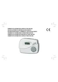
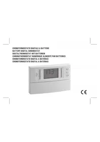
| Product type | Thermostat (radio chronothermostat) |
| Brand | Seitron |
| Model | DCPA80BC |
| Power supply | 2 AA 1.5 V alkaline batteries |
| Battery life | Approximately 1 year |
| Comfort adjustment range | 10 °C to 30 °C |
| Economic adjustment range | 10 °C to 30 °C |
| Differential | 0.2 °C asymmetric |
| Temperature sensor | NTC 100 kΩ @ 25°C, accuracy ±1°C |
| Temperature detection frequency | Every 3 minutes |
| Radio output power | 10 dBm max (ERP) |
| Modulation | AM (ASK) |
| Antenna | Integrated |
| Maximum range | >300 m outdoors, 50 m indoors |
| Protection rating | IP30 |
| Operating temperature | 0 °C to 40 °C |
| Storage temperature | -10 °C to 50 °C |
| Permissible humidity | 20% to 80% RH (non-condensing) |
| Housing material | ABS V0 self-extinguishing |
| Color | Safety white (RAL 9003) |
| Mounting | On 60 mm or 83 mm centers (3-module flush-mount box) |
| Programming modes | Weekly or daily |
| Functions | Comfort, economy, summer/winter, antifreeze, vacation, optimization, proportional time, test mode |
| Display | Room temperature or time |
| External probe | Optional (NTC 100kΩ) |
| Telephone interface | Optional |
Frequently Asked Questions - DCPA80BC Seitron
User questions about DCPA80BC Seitron
0 question about this device. Answer the ones you know or ask your own.
Ask a new question about this device
Download the instructions for your Thermostat in PDF format for free! Find your manual DCPA80BC - Seitron and take your electronic device back in hand. On this page are published all the documents necessary for the use of your device. DCPA80BC by Seitron.