
CLLi - Laser pointer STANLEY - Free user manual and instructions
Find the device manual for free CLLi STANLEY in PDF.
| Product Type | Cross Line Laser Level |
| Brand | Stanley |
| Model | CLLi |
| Dimensions (L x W x H) | 88 mm x 48 mm x 90 mm |
| Weight (without batteries or base) | 230 g |
| Power Supply | 3 AA batteries (alkaline) - 4.5 V |
| Battery Life | 16 hours |
| Leveling Accuracy | ≤ 4 mm / 10 m |
| Self-Leveling Range | ± 4° |
| Working Distance | ≤ 10 m |
| Laser Class | Class 1 (EN 60825-1) |
| Laser Wavelength | 635 nm ± 5 nm |
| Protection Rating | IP54 |
| Operating Temperature | -10 °C to +40 °C |
| Storage Temperature | -20 °C to +60 °C |
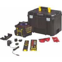
| Package Contents | Laser tool, tripod, L-bracket, pole clamp, target, carrying case, 3 AA batteries, user manual |
| Projection Modes | Horizontal line, vertical line, cross lines |
| Self-Leveling | Yes (can be disabled for sloped projection) |
| Transport Lock | Yes, protects leveling mechanism |
| Low Battery Indicator | Yes, beam intensity decreases |
| Housing Material | Durable plastic |
| Warranty | 1 year (parts and labor) |
| Maintenance and Cleaning | Clean laser windows with a soft, dry cloth. Do not use solvents. Store in case. |
| Spare Parts and Repairability | No user-serviceable parts. Contact Stanley customer service. |
| Safety Instructions | Do not stare into beam with optical instruments. Avoid direct eye contact. |
Frequently Asked Questions - CLLi STANLEY
User questions about CLLi STANLEY
0 question about this device. Answer the ones you know or ask your own.
Ask a new question about this device
Download the instructions for your Laser pointer in PDF format for free! Find your manual CLLi - STANLEY and take your electronic device back in hand. On this page are published all the documents necessary for the use of your device. CLLi by STANLEY.
USER MANUAL CLLi STANLEY
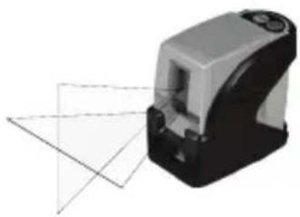
2 - Beam Self-Leveling Cross Line Laser
CLLi
natural_image
Close-up of a black and white plastic device with control buttons (no visible text or symbols)
natural_image
Abstract icon of an open book with a lowercase 'i' and two horizontal lines below (no text or symbols)77-117
Please read these instructions before operating the product

Self-Leveling
GB
D
F
I
E
PT
NL
DK
SE
GB
Contents
- Safety
- Product Description
- Specifications
- Operating Instructions
- Calibration
- Maintenance and Care
- Warranty
Safety
User Safety
Carefully read the Safety Instructions and User Manual before using this product. The person responsible for the instrument must ensure that all users understand and adhere to these instructions.
Retain this manual for future reference.
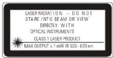
IMPORTANT: The following labels are on your laser tool for your convenience and safety. They indicate where the laser light is emitted by the level. ALWAYS BE AWARE of their location when using the level.
EN 60825-1
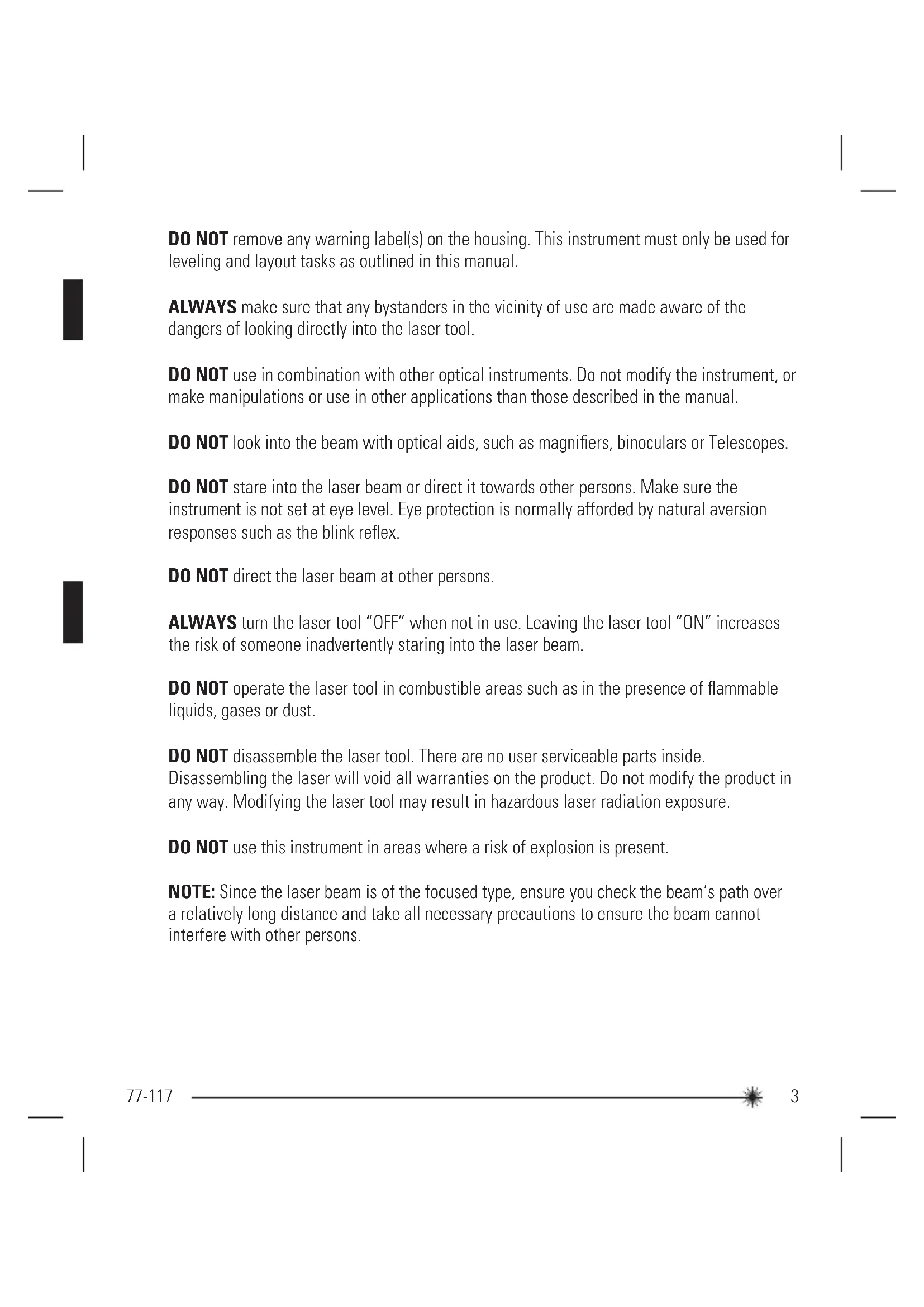
DO NOT remove any warning label(s) on the housing. This instrument must only be used for leveling and layout tasks as outlined in this manual.
ALWAYS make sure that any bystanders in the vicinity of use are made aware of the dangers of looking directly into the laser tool.
DO NOT use in combination with other optical instruments. Do not modify the instrument, or make manipulations or use in other applications than those described in the manual.
DO NOT look into the beam with optical aids, such as magnifiers, binoculars or Telescopes.
DO NOT stare into the laser beam or direct it towards other persons. Make sure the instrument is not set at eye level. Eye protection is normally afforded by natural aversion responses such as the blink reflex.
DO NOT direct the laser beam at other persons.
ALWAYS turn the laser tool "OFF" when not in use. Leaving the laser tool "ON" increases the risk of someone inadvertently staring into the laser beam.
DO NOT operate the laser tool in combustible areas such as in the presence of flammable liquids, gases or dust.
DO NOT disassemble the laser tool. There are no user serviceable parts inside. Disassembling the laser will void all warranties on the product. Do not modify the product in any way. Modifying the laser tool may result in hazardous laser radiation exposure.
DO NOT use this instrument in areas where a risk of explosion is present.
NOTE: Since the laser beam is of the focused type, ensure you check the beam's path over a relatively long distance and take all necessary precautions to ensure the beam cannot interfere with other persons.
Battery Safety
WARNING: Batteries can explode or leak and can cause injury or fire. To reduce this risk:
ALWAYS follow all instructions and warnings on the battery label and package.
DO NOT short any battery terminals
DO NOT charge alkaline batteries.
DO NOT mix old and new batteries. Replace all of them at the same time with new batteries of the same brand and type.
DO NOT mix battery chemistries.
DO NOT dispose of batteries in fire.
ALWAYS keep batteries out of reach of children.
ALWAYS remove batteries if the device will not be used for several months.
NOTE: Ensure that the correct batteries as recommended are used.
NOTE: Ensure the batteries are inserted in the correct manner, with the correct polarity.
End of Life
DO NOT dispose of this product with household waste.
ALWAYS dispose of batteries per local code.

PLEASE RECYCLE in line with local provisions for the collection and disposal of electrical and electronic waste under the WEEE Directive.
Declaration of Conformity
The Stanley Works declares that the CE Mark has been applied to this product in accordance with the CE Marking Directive 93/68/EEC.
This product conforms with EN60825-1:2007.
For further details please refer to www.stanleyworks.com.
EN 60825-1


ROHS Compliant
Product Description

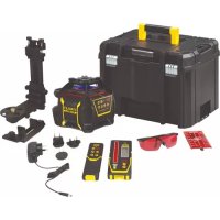
Package Contents
- Laser Unit
- Tripod
- L-Type Bracket
- Pole Clamp (attaches to L-Type Bracket)
- Laser Target
- Carrying Case
- Batteries (3 x AA)
- User Manual
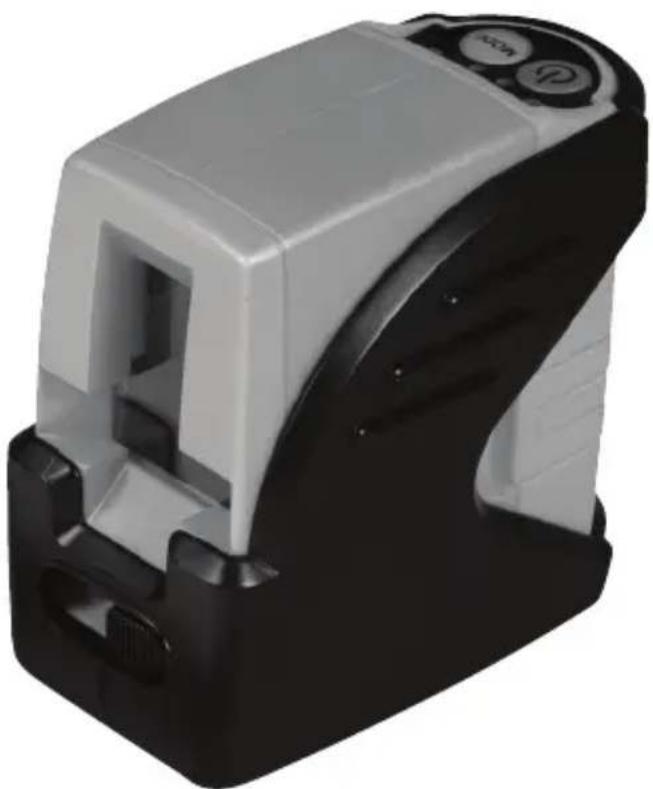
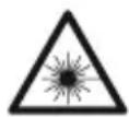
Product Overview
Laser Unit
-
Window for Cross Beam Laser
-
Transport Lock
-
Keyboard
-
Laser Warning Label
-
Battery Compartment Cover
-
1/4 - 20 Threaded Mount
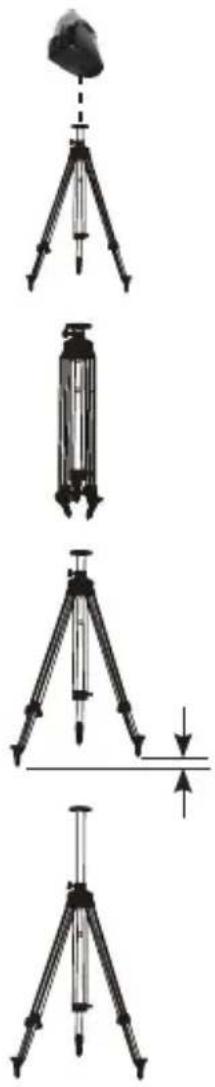
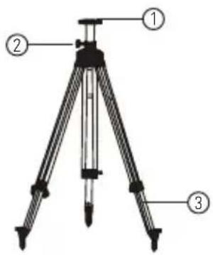
Tripod

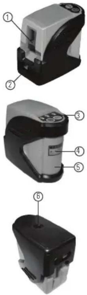
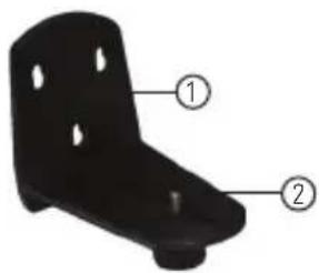
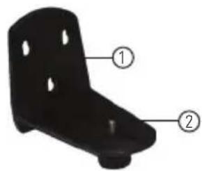
L-Type Bracket
- 1/4 - 20 Screw Mount
- Elevator Column
- Adjustable Legs
natural_image
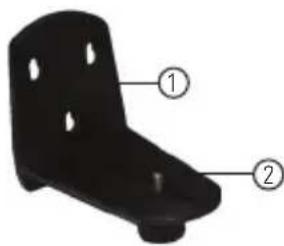
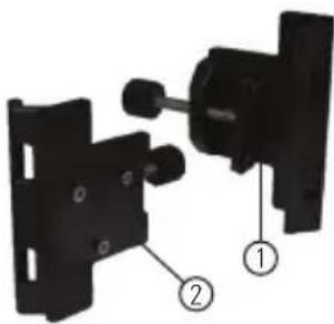
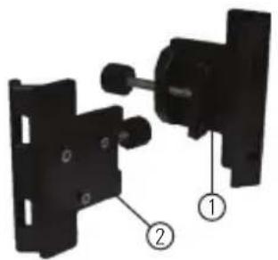
Black metal bracket component with two labeled parts (① and ②), no text or symbols present.Pole Clamp
- Keyhole Slots
- 1/4 - 20 Screw Mount
natural_image
Mechanical assembly diagram showing two components with numbered labels (1 and 2), no readable text or symbols present.- Clamp
- 3 Pin Key
Specifications
Leveling Accuracy: ≤ 4 mm / 10 m ( ≤ 5/32 in / 30 ft)
Horizontal / Vertical Accuracy ≤ 4 mm / 10 m ( ≤ 5/32 in / 30 ft)
Working Range: Self-Leveling to ±4^
Working Distance: ≤ 10 m ( ≤ 30 ft)
Laser Class: Class 1
Laser Wavelength: 635 nm ± 5 nm
Operating Time: 16 h
Power Voltage: 4,5 V
Power Supply: 3 x AA Batteries (Alkaline)
IP Rating: IP54
Operating Temperature Range: -10^ C to +40^ C ( +14^ F to +104^ F)
Storage Temperature Range: -20^ C to +60^ C ( -4^ F to +140^ F)
Weight (without Base and Batteries): 230 g (8 oz)
Size: 88 mm × 48 mm × 90 mm (3 1/2 in × 1 7/8 in × 3 1/2 in)
Operating Instructions
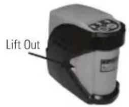
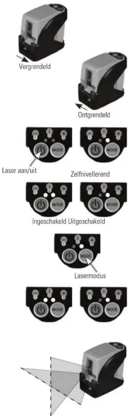
Battery Installation / Removal
- Turn laser unit to back. Open battery compartment cover by bending tab out to unlock.
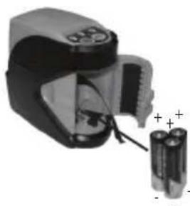
- Install / Remove batteries. Orient batteries correctly when placing into laser unit.
- Close and lock battery compartment cover. Be sure tab snaps back into locking feature.
natural_image
Close-up of a battery pack with two batteries and a plug inserted, no visible text or symbols
natural_image
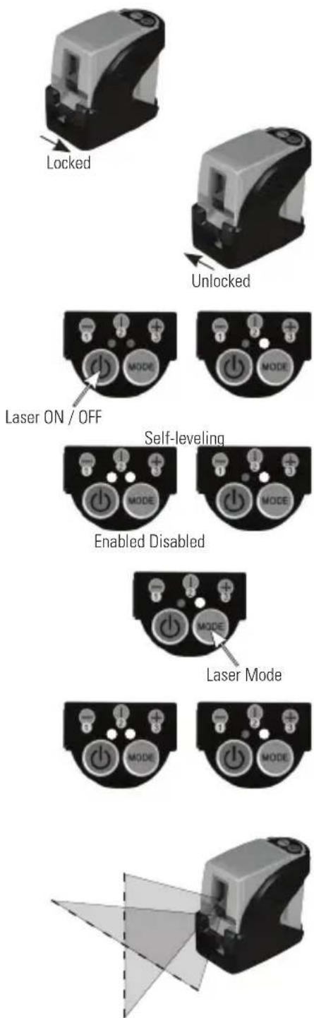
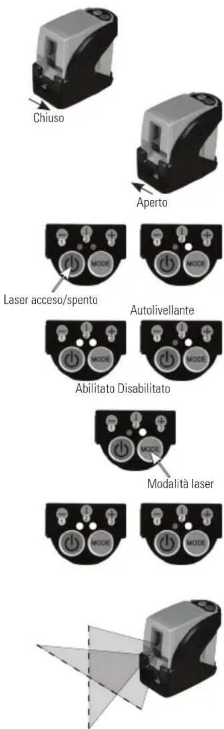
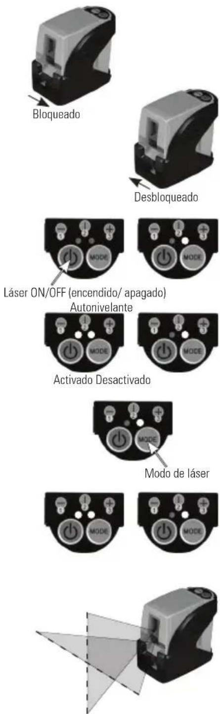
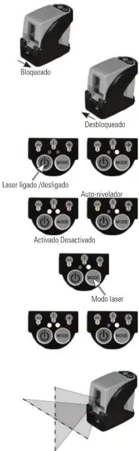
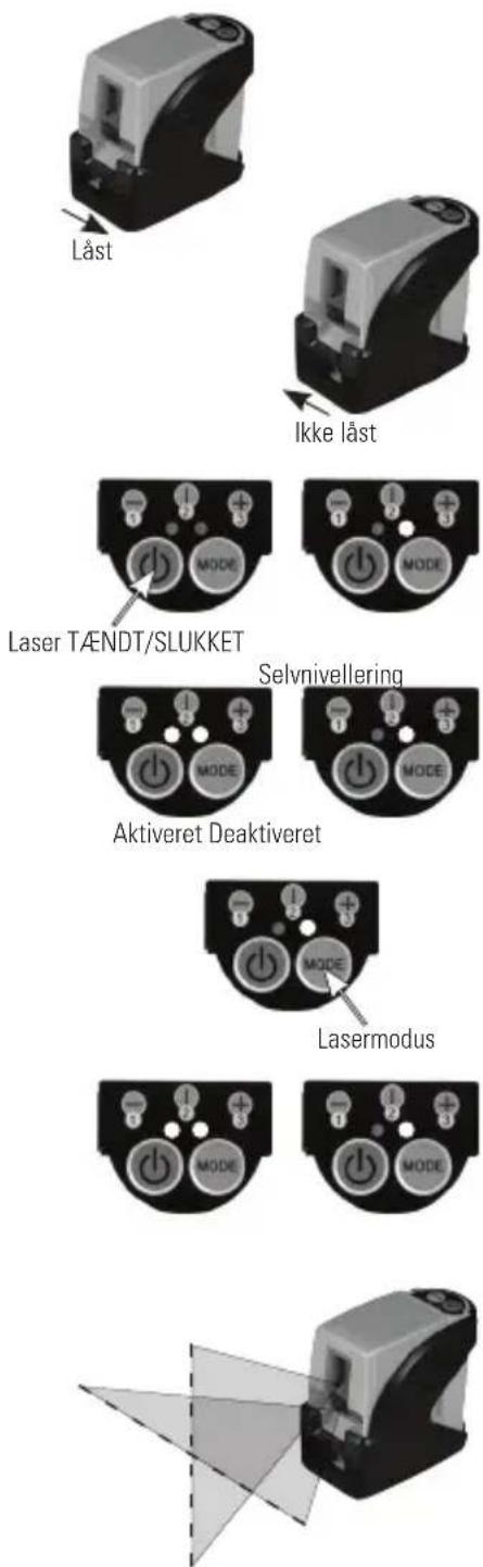
Close-up of a handheld electronic device with a black and gray casing and a white top, showing a small circular button and an arrow pointing to the side (no visible text or symbols)Laser Unit
-
Transport lock in locked position. Self-leveling function is disabled.
-
Transport lock in unlocked position. Self-leveling function is enabled.
-
Press power key to power laser ON / OFF. Right LED lights green when laser power is on.
-
Left LED lights blue when laser power is on with self-leveling function disabled. LED is off when self-leveling function enabled.
-
Press laser mode key to toggle through available laser modes - horizontal only, vertical only, both horizontal and vertical.
-
Laser power and laser mode keys are always functional. Can be used when self-leveling function is both enabled or disabled.
-
Laser beam(s) blink to indicate the laser unit is out of the working range. Reposition laser unit to be more level.
natural_image
3D rendering of a mechanical device with transparent screen and black casing (no text or symbols visible)- Laser beam(s) will dim when battery power is low. Replace batteries.
Tripod
natural_image
Four sequential diagrams showing a tripod setup with a load device and a horizontal line, no text or symbols present.-
1/4 - 20 screw mount to attach laser unit.
-
Foldable for easier transport.
-
Legs are adjustable for uneven ground.
-
Elevator column adjustable for different heights.
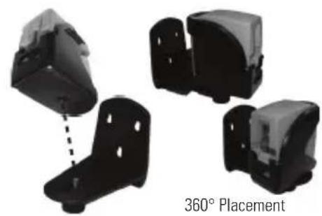
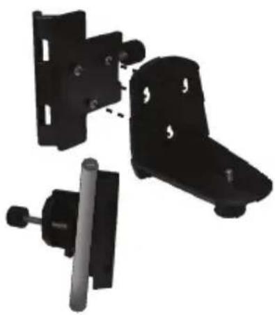
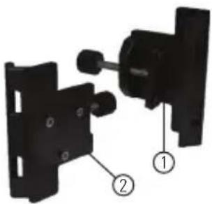
L-Type Bracket and Pole Clamp
natural_image
Four black plastic bracket components with a dashed connection line, labeled '360° Placement' below (no other text or symbols)- 1/4 - 20 screw mount to attach laser unit. Allows for full 360° placement of the laser unit.
natural_image
Three black metal mechanical components with mounting holes, shown from different angles (no text or symbols visible)- Fasten pole clamp to L-type bracket to allow use with tripod or other optional accessories.
Applications
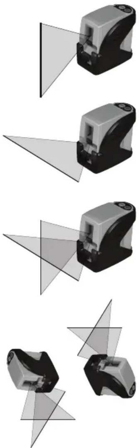
natural_image
Four grayscale 3D mechanical components with triangular projections, shown from different angles (no text or symbols)1. Plumb:
Using the vertical laser beam, establish a vertical reference plane. Position the desired object(s) until they are aligned with the vertical reference plane to ensure object(s) are plumb.
2. Level:
Using the horizontal laser beam, establish a horizontal reference plane. Position the desired object(s) until they are aligned with the horizontal reference plane to ensure object(s) are level.
3. Square:
Using both the vertical and horizontal laser beams, establish a point where the vertical and horizontal beams cross. Position the desired object(s) until they are aligned with both the vertical and horizontal laser beams to ensure object(s) are square.
4. Self-Leveling Disabled:
Disabling self-leveling function allows laser unit to project a rigid laser beam in any orientation.
Calibration

NOTE: The laser unit has been calibrated at the time of manufacturing. Periodically check the accuracy of the laser unit to ensure that the calibrated specifications are maintained.
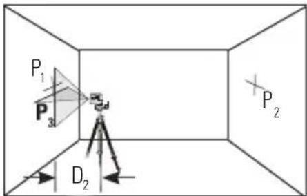
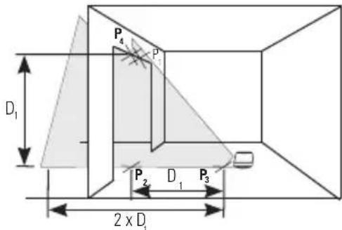
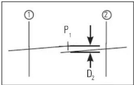
Level Beam Accuracy
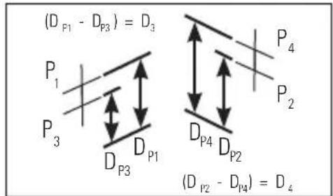
- Place laser unit as shown with laser ON. Mark point P_1 at cross.
- Rotate laser unit 180^ and mark point P at cross.
- Move laser unit close to wall and mark point P_3 at cross.
- Rotate laser unit 180^ and mark point P at cross.
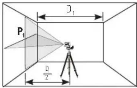

- Measure the vertical distance from the floor to each point. Calculate the difference between distances D_P1 and D_P3 to get D_3 and distances D_P2 and D_P4 to get D_4 .
- Calculate the maximum allowed offset distance and compare to the difference of D_3 and D_4 as shown in the equation. If the sum is not less than or equal to the calculated maximum offset distance the unit must be returned to your Stanley Distributor.
Maximum Offset Distance:
$$ \begin{array}{l} = 0. 4 \frac {\mathrm{mm}}{\mathrm{m}} \times \left(\mathrm{D} _ {1} \mathrm{m} - (2 \times \mathrm{D} _ {2} \mathrm{m})\right) \ \text { I m a x } = 0. 0 0 4 8 \frac {\mathrm{in}}{\mathrm{ft}} \times \left(\mathrm{D} _ {1} \mathrm{ft} - (2 \times \mathrm{D} _ {2} \mathrm{ft})\right) \ \end{array} $$
Compare:
$$ D _ {3} - D _ {4} \leq \pm M a x $$
Example: D_1 = 10 m , D_2 = 0.5 m
$$ D _ {P 1} = 3 0, 7 5 \mathrm{mm}, D _ {P 2} = 2 9 \mathrm{mm}, D _ {P 3} = 3 0 \mathrm{mm}, D _ {P 4} = 2 9, 7 5 \mathrm{mm} $$
$$ D _ {3} = (3 0, 7 5 \mathrm{mm} - 3 0 \mathrm{mm}) = 0, 7 5 \mathrm{mm} $$
$$ D _ {4} = (2 9 m m - 2 9, 7 5 m m) = - 0. 7 5 \mathrm{mm} $$
$$ 0. 4 \frac {\mathrm{mm}}{\mathrm{m}} \times (1 0 \mathrm{m} - (2 \times 0. 5 \mathrm{m}) = 3. 6 \mathrm{mm} (\text {maximum allowed offset distance}) $$
$$ (0, 7 5 \mathrm{mm}) - (- 0, 7 5 \mathrm{mm}) = 1, 5 \mathrm{mm} $$
$$ 1, 5 \mathrm{mm} \leq 3, 6 \mathrm{mm} (\text { TRUE }, \text { unit is within calibration }) $$
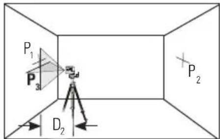
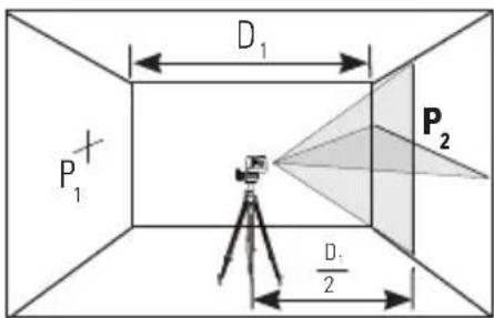
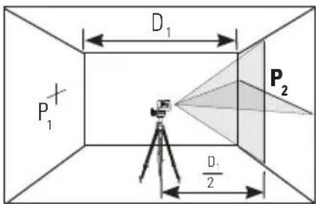
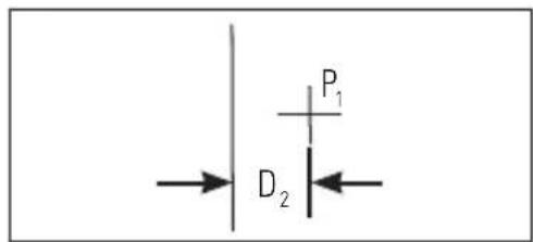
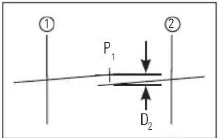
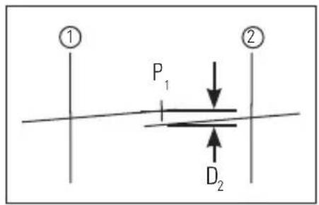
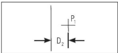
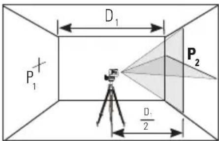
Horizontal Beam Accuracy
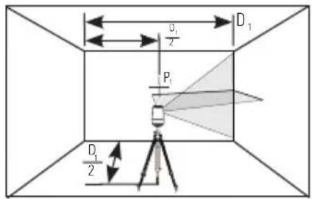
- Place laser unit as shown with laser ON. Aim vertical beam to first corner or reference point. Measure out half of the distance D_1 and mark point P_1 .
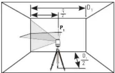
- Rotate laser unit to other corner or reference point.
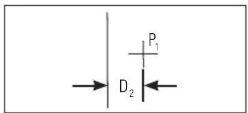
- Measure the vertical distances between P_1 and the horizontal beam from the 2nd location.
- Calculate the maximum allowed offset distance and compare to D_2 . If D_2 is not less than or equal to the calculated maximum offset distance the unit must be returned to your Stanley Distributor.

Maximum Offset Distance:
$$ \begin{array}{l} = 0. 4 \frac {\mathrm{mm}}{\mathrm{m}} \times D _ {1} \mathrm{m} \ \text { Max } = 0, 0 0 4 8 \frac {\mathrm{in}}{\mathrm{ft}} \times D _ {1} \mathrm{ft} \ \end{array} $$
Compare:
$$ D _ {2} \leq \text { Max } $$
Example: D_1 = 5 m , D_2 = 1 mm
0,4 x 5 m = 2 mm (maximum allowed offset distance)
1 mm ≤ 2 mm (TRUE, unit is within calibration)
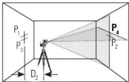
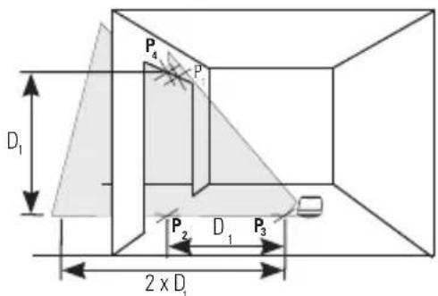
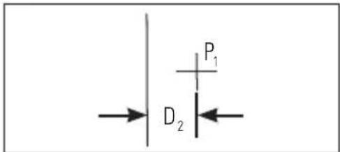
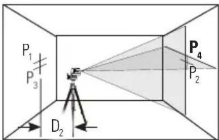
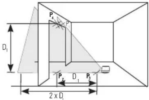
Vertical Beam Accuracy
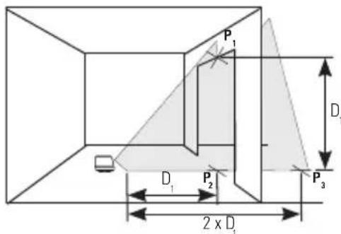
- Measure the height of a door jamb or reference point to get distance D_1 . Place laser unit as shown with laser ON. Aim vertical beam towards door jamb or reference point. Mark points P_1, P_2 , and P_3 as shown.
- Move laser unit to opposite side of door jamb or reference point and align vertical beam with P_2 and P_3 .
- Measure the horizontal distances between P_1 and the vertical beam from the 2nd location.
- Calculate the maximum allowed offset distance and compare to D_2 . If D_2 is not less than or equal to the calculated maximum offset distance the unit must be returned to your Stanley Distributor.


Maximum Offset Distance:
$$ \begin{array}{l} = 0. 8 \frac {\mathrm{mm}}{\mathrm{m}} \times D _ {1} \mathrm{m} \ = 0, 0 0 9 6 \frac {\text { in }}{\text { ft }} \times D _ {1} \text { ft } \ \end{array} $$
Compare:
$$ D _ {2} \leq \text { Max } $$
Example: D_1 = 2 m , D_2 = 0.5 mm
0.8 × 2 = 1.6mm (maximum allowed offset distance)
0,5 mm ≤ 1,6 mm (TRUE, unit is within calibration)
Maintenance and Care
Laser unit is not waterproof. DO NOT allow to get wet. Damage to internal circuits may result.
DO NOT leave laser unit in direct sunlight or expose it to high temperatures. The housing and some internal parts are made of plastic and may become deformed at high temperatures.
DO NOT store the laser unit in a cold environment. Moisture may form on interior parts when warming up. This moisture could fog up laser windows and cause corrosion of internal circuit boards.
When working in dusty locations, some dirt may collect on the laser window. Remove any moisture or dirt with a soft, dry cloth.
DO NOT use aggressive cleaning agents or solvents.
Store the laser unit in its case when not in use. If storing for extended time, remove batteries before storage to prevent possible damage to the instrument.
One Year Warranty
Stanley Tools warrants its electronic measuring tools against deficiencies in materials and/or workmanship for one year from date of purchase.
Deficient products will be repaired or replaced, at Stanley Tools' option, if sent together with proof of purchase to:
Stanley UK Sales Limited
Gowerton Road
Brackmills, Northampton NN4 7BW
This Warranty does not cover deficiencies caused by accidental damage, wear and tear, use other than in accordance with the manufacturer's instructions or repair or alteration of this product not authorised by Stanley Tools.
Repair or replacement under this Warranty does not affect the expiry date of the Warranty.
To the extent permitted by law, Stanley Tools shall not be liable under this Warranty for indirect or consequential loss resulting from deficiencies in this product.
This Warranty may not be varied without the authorisation of Stanley Tools.
This Warranty does not affect the statutory rights of consumer purchasers of this product.
This Warranty shall be governed by and construed in accordance with the laws of England and Stanley Tools and the purchaser each irrevocably agrees to submit to the exclusive jurisdiction of the courts of England over any claim or matter arising under or in connection with this Warranty.
IMPORTANT NOTE: The customer is responsible for the correct use and care of the instrument. Moreover, the customer is completely responsible for periodically checking the accuracy of the laser unit, and therefore for the calibration of the instrument.
Calibration and care are not covered by warranty.
Subject to change without notice
D
Inhaltsverzeichnis
L-Halterung
natural_image
Black metal bracket component with two labeled parts (① and ②), no text or symbols present.Stabklemme
natural_image
Mechanical assembly diagram showing two components with numbered labels (1 and 2), no readable text or symbols present.- Klemme
- 3 Passstifte
Technische Daten
Nivelliergenauigkeit: ≤ 4 mm / 10 m (≤ 5/32 Zoll / 30 ft)
Horizontale / Vertikale Genauigkeit ≤ 4 mm / 10 m (≤ 5/32 Zoll / 30 ft)
natural_image
3D rendering of a mechanical device with transparent screen and black casing (no text or symbols visible)natural_image
Four sequential diagrams showing a tripod-mounted surveying instrument with an upward arrow indicating motion (no text or symbols present)natural_image
Four black plastic mechanical components with a dashed line indicating connection, labeled '360°-Anordnung' (no other text or symbols)natural_image
Three black metal mechanical components with mounting holes, shown from different angles (no text or symbols visible)natural_image
Four grayscale 3D mechanical components with triangular projections and triangular bases, no visible text or symbols- Lot:


Maximaler Versatz:
$$ \begin{array}{l} = 0, 4 \frac {\mathrm{mm}}{\mathrm{m}} \times D _ {1} \mathrm{m} \ \text { Max } = 0, 0 0 4 8 \frac {\text { Zoll }}{\text { ft }} \times D _ {1} \text { ft } \ \end{array} $$
Vergleich:
$$ D _ {2} \leq \text { Max } $$
Beispiel: D_1 = 5 m , D_2 = 1 mm
Maximaler Versatz:
$$ \begin{array}{l} = 0. 8 \frac {\mathrm{mm}}{\mathrm{m}} \times D _ {1} \mathrm{m} \ = 0, 0 0 9 6 \frac {Z _ {\text {oll}}}{\mathrm{ft}} \times D _ {1} \mathrm{ft} \ \end{array} $$
Vergleich:
$$ D _ {2} \leq \text { Max } $$
Beispiel: D_1 = 2 m , D_2 = 0.5 mm
Support en L
natural_image
Black metal bracket component with two labeled parts (① and ②), no text or symbols present.natural_image
Mechanical assembly diagram showing two components with numbered labels (1 and 2), no readable text or symbols present.natural_image
3D rendering of a mechanical device with transparent screen and black casing (no text or symbols visible)natural_image
Four sequential diagrams showing a tripod-mounted surveying instrument with an upward arrow indicating motion (no text or symbols present)natural_image
Four black plastic mechanical components with a dotted connection line, labeled 'Positionnement à 360°' (no other text or symbols)natural_image
Three black metal mechanical components with mounting holes, shown from different angles (no text or symbols visible)natural_image
Four grayscale 3D mechanical components with triangular projections and triangular bases, no visible text or symbols1. Aplomb :


Décalage maximal :
$$ \begin{array}{l} = 0. 4 \frac {\mathrm{mm}}{\mathrm{m}} \times D _ {1} \mathrm{m} \ \text { Max } = 0, 0 0 4 8 \frac {\mathrm{po.}}{\mathrm{pi.}} \times D _ {1} \mathrm{pi.} \ \end{array} $$
Comparator :
$$ D _ {2} \leq \text { Max } $$
Example: D_1 = 5 m , D_2 = 1 mm

Décalage maximal :
$$ \begin{array}{l} = 0. 8 \frac {\mathrm{mm}}{\mathrm{m}} \times D, \mathrm{m} \ = 0, 0 0 9 6 \frac {\mathrm{po.}}{\mathrm{pi.}} \times D _ {1} \text { pi. } \ \end{array} $$
Comparator :
$$ D _ {2} \leq \text { Max } $$
Example: D_1 = 2 m , D_2 = 0.5 mm
Stanley Tools France
Supporto a L
natural_image
Black metal bracket component with two labeled parts (① and ②), no text or symbols present.Morsetto dell'asta
- Fessure a occhiello
- Innesto a vite 1/4 - 20
natural_image
Mechanical assembly diagram showing two components with numbered labels (1 and 2), no readable text or symbols present.(3 1/2 in × 1 7/8 in × 3 1/2 in)
natural_image
Close-up of a battery pack with two batteries and a plug inserted (no visible text or symbols)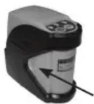
natural_image
Close-up of a handheld electronic device with a black and white casing and a circular button (no visible text or symbols)Unità laser
natural_image
3D rendering of a mechanical device with transparent screen and black casing (no text or symbols visible)natural_image
Four sequential diagrams showing a tripod-mounted surveying instrument with a load applied, no text or symbols present.natural_image
Three black plastic mechanical components with mounting holes, connected by a dotted line to a 360° angle indicator (no text or symbols on components)natural_image
Three black metal mechanical components with mounting holes and a handle, shown against a white background (no text or symbols visible)natural_image
Four grayscale 3D mechanical components with triangular projections and triangular bases, no text or symbols visible- A piombo:


Soporte tipo L
- Montura roscada 1/4 - 20
- Columna elevadora
- Patas ajustables

natural_image
Black metal bracket component with two labeled parts (① and ②), no text or symbols present.Abrazadera
natural_image
Mechanical assembly diagram showing two components with numbered labels (1 and 2), no readable text or symbols present.- Pinza
- Tecla de 3 clavijas
Especificaciones
Dimensiones: 88 mm. × 48 mm. × 90 mm (3 1/2 in × 1 7/8 in × 3 1/2 in)
natural_image
Close-up of a battery pack with two batteries and a charging plug, no visible text or symbols
natural_image
Close-up of a handheld electronic device with a black and gray casing and a white top, showing a small circular button and an arrow pointing to the side (no visible text or symbols)Unidad láser
natural_image
3D rendering of a mechanical device with transparent alignment lines (no text or symbols visible)natural_image
Four sequential diagrams showing a tripod-mounted surveying instrument with a load applied, no text or symbols present.natural_image
Four black plastic mechanical components with a dotted connection line, labeled 'Colocación a 360°' below (no other text or symbols)natural_image
Three black metal mechanical components with mounting holes, shown from different angles (no text or symbols visible)natural_image
Four grayscale 3D mechanical components with triangular projections, shown from different angles (no text or symbols)- Plomada:


Suporte em L
natural_image
Black metal bracket component with two labeled parts (1 and 2), no text or symbols present.Pólo do fixador
- Ranhuras
- Parafuso de montagem de 1/4 - 20
natural_image
Mechanical assembly diagram showing two components with labeled parts (1 and 2), no readable text or symbols present.- Fixador
- Cavilha de 3 pinos
Especificações
natural_image
Close-up of a battery pack with two batteries and a charging plug, no visible text or symbols
natural_image
Close-up of a handheld electronic device with a black and white casing and a circular button, showing an arrow pointing to the side (no visible text or symbols)Unidade de laser
natural_image
3D rendering of a mechanical device with transparent screen and black casing (no text or symbols visible)natural_image
Four sequential diagrams showing a tripod-mounted surveying instrument with a load, no text or symbols present.natural_image
Four black plastic mechanical components with a dotted line indicating a 360° direction (no text or symbols on the components themselves)natural_image
Three black metal mechanical components with mounting holes and a handle, shown from different angles (no text or symbols visible)natural_image
Four grayscale 3D mechanical components with triangular projections and triangular bases, no visible text or symbols1. Aprumar:


L-vormige steun
- 1/4 - 20 schroeffitting
- Verstelbare middenkolom
- Verstelbare poten
natural_image
Black metal bracket component with two labeled parts (① and ②), no text or symbols present.Paalklem
- Opening
- 1/4 - 20 schroeffitting

natural_image
Mechanical assembly diagram showing two components with numbered labels (1 and 2), no readable text or symbols present.- Klem
- 3 Pin key
Technische gegevens
Nivelleringsnauwkeurigheid: ≤ 4 mm / 10 m (≤ 5/81,28 cm / 30 ft)
Nauwkeurigheid horizontaal / verticaal ≤ 4 mm / 10 m (≤ 5/81,28 cm / 30 ft)
Afmeting: 88 mm × 48 mm × 90 mm (3 1/2 in × 1 7/8 in × 3 1/2 in)
natural_image
Close-up of a mechanical device with a label pointing to the side (no readable text or symbols)
natural_image
Close-up of a battery pack with two batteries and a plug inserted, no visible text or symbols
natural_image
Close-up of a handheld electronic device with a black and gray casing and a white label (no visible text or symbols)Laserapparaat
natural_image
3D printer with transparent screen and black base, no visible text or symbolsnatural_image
Four sequential diagrams showing a tripod-mounted surveying instrument with an upward arrow indicating motion (no text or symbols present)natural_image
Four black plastic mechanical components with a dashed line indicating a 360° opstelling angle (no text or symbols on the components themselves)natural_image
Three black metal mechanical components with mounting holes, shown from different angles (no text or symbols visible)natural_image
Four grayscale 3D mechanical components with triangular projections and triangular bases, no visible text or symbols- Verticaal stellen:


-
Vindue til krydslinjelaser
-
Transportlås
-
Tastatur
-
Laseradvarselsmærkat
-
Dæksel til batterirum
-
1/4 - 20 monteringsgevind
Trefod
L-beslag
- 1/4 - 20 skruebeslag
- Elevationssøjle
- Justerbare ben
natural_image
Black metal bracket component with two labeled parts (① and ②), no text or symbols present.Stangklemme
- Nøglehulsåbninger
- 1/4 - 20 skruebeslag

natural_image
Mechanical assembly diagram showing two components with numbered labels (1 and 2), no readable text or symbols present.- Klemme
- 3-bensstik
Specifikationer
natural_image
Close-up of a battery pack with two batteries and a charging plug, no visible text or symbols
natural_image
Close-up of a handheld electronic device with a black and gray casing and a white top, showing a small circular button and an arrow pointing to the side (no visible text or symbols)Laserenhed
natural_image
3D rendering of a mechanical device with transparent screen and black casing (no text or symbols visible)natural_image
Four sequential diagrams showing a tripod-mounted surveying instrument with an upward arrow indicating motion (no text or symbols present)natural_image
Four black plastic bracket components with a dotted connection line, labeled '360° placering' below (no other text or symbols)natural_image
Three black metal mechanical components with mounting holes, shown from different angles (no text or symbols visible)natural_image
Four grayscale 3D mechanical components with triangular projections and triangular bases, no visible text or symbols- I lod:
Brug den vertikale laserstråle til at danne et vertikalt referenceniveau. Anbring den/de ønskede genstand(e) på linje med det vertikale referenceniveau for at sikre, at den/de er i lod.
- | vater:


L-fäste
natural_image
Black metal bracket component with two labeled parts (1 and 2), no text or symbols present.Stångklämma
natural_image
Mechanical assembly diagram showing two components with labeled parts (1 and 2), no readable text or symbols present.(3 1/2 in × 1 7/8 in × 3 1/2 in)
Bruksanvisning
natural_image
Close-up of a battery pack with two batteries and a charging plug, no visible text or symbols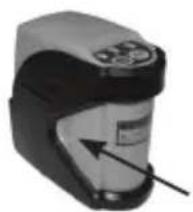
natural_image
Close-up of a handheld electronic device with a black and gray casing and a white label (no visible text or symbols)Laserenhet

natural_image
3D printer with transparent screen and black base, no visible text or symbolsnatural_image
Four sequential diagrams showing a tripod-mounted surveying instrument with an upward arrow indicating motion (no text or symbols present)natural_image
Four black plastic mechanical components with a dashed connection line, labeled '360° vridning' below (no other text or symbols)natural_image
Three black metal mechanical components with mounting holes, shown from different angles (no text or symbols visible)natural_image
Four grayscale 3D mechanical components with triangular projections and triangular bases, no visible text or symbols- Lod:


© 2010 The Stanley Works
Stanley Europe, Egide Walschaertsstraat 14-16,
2800 Mechelen, Belgium
Issue 1 03/10
WWW.STANLEYWORKS.COM


- - Beam Self-Leveling Cross Line Laser
- CLLi
- GB
- Contents
- Safety
- User Safety
- Battery Safety
- End of Life
- Declaration of Conformity
- Product Description
- Package Contents
- Product Overview
- Specifications
- Operating Instructions
- Battery Installation / Removal
- Laser Unit
- Tripod
- L-Type Bracket and Pole Clamp
- Applications
- Plumb:
- Level:
- Square:
- Self-Leveling Disabled:
- Calibration
- Level Beam Accuracy
- Maximum Offset Distance:
- Horizontal Beam Accuracy
- Vertical Beam Accuracy
- Maintenance and Care
- One Year Warranty
- D
- Inhaltsverzeichnis
- Technische Daten
- Support en L
- Aplomb :
- Stanley Tools France
- Supporto a L
- Morsetto dell'asta
- Unità laser
- Especificaciones
- Unidad láser
- Especificações
- Unidade de laser
- Aprumar:
- Technische gegevens
- Laserapparaat
- Specifikationer
- Laserenhed
- Bruksanvisning
- Laserenhet
Brand : STANLEY
Model : CLLi
Category : Laser pointer