S 5002 - Heating Trumatic - Free user manual and instructions
Find the device manual for free S 5002 Trumatic in PDF.


Frequently Asked Questions - S 5002 Trumatic
User questions about S 5002 Trumatic
0 question about this device. Answer the ones you know or ask your own.
Ask a new question about this device
Download the instructions for your Heating in PDF format for free! Find your manual S 5002 - Trumatic and take your electronic device back in hand. On this page are published all the documents necessary for the use of your device. S 5002 by Trumatic.
USER MANUAL S 5002 Trumatic
Operating instructions
Page

Brugsanvising
To be kept in the vehicle!
Skal medbringes i koretojet!

Mode d'emploi
Page

Trumatic S 3002 (P), S 5002
Gasart
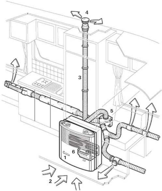
1 Liquid gas heater Trumatic S
2 Combustion air supply
3 Exhaust duct with insulating duct
4 Exhaust cowl
5 Trumavent fan and comfort kit with Airmix (for warm air distribution) - optional
6 Truma Ultraheat (additional electric heating 230 V) - optional
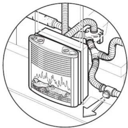
Front case with flame effect (Trumatic S 5002 only)
Safety instructions
The use of upright gas cylinders from which gas is taken in the gas phase is mandatory for the operation of gas regulators, gas equipment and gas systems. Gas cylinders from which gas is taken in the liquid phase (e.g. for fork lifts) must not be used, since they would result in damage to the gas system.
If the gas system is leaking or if there is a smell of gas:
extinguish all naked flames
- do not smoke
- switch off the appliances
- shut off the gas cylinder
open windows and door
- do not actuate any electrical switches
have the entire system checked by an expert!

Repairs may only be carried out by an expert!
A new O-ring must always be installed after dismantling the exhaust duct!
Guarantee claims, warranty claims and acceptance of liability will be ruled out in the event of the following:
- modifications to the unit (including accessories),
modifications to the exhaust duct and the cowl, - failure to use original Truma parts as replacement parts and accessories,
- failure to follow the installation and operating instructions.
It also becomes illegal to use the appliance, and in some countries this even makes it illegal to use the vehicle.
The operating pressure for the gas supply is 30 mbar and must correspond to the operating pressure of the appliance (see data plate).
Liquid gas installations must accord with the technical and administrative regulations of the individual country in which they are to be used (e.g. EN 1949 for motor vehicles). National specifications and regulations in Germany (e.g. the DVGW operational data sheet G 607) must be respected.
In Germany, the gas system must be retested every 2 years by a liquid gas specialist (DVFG, TÜV, DEKRA). The test must be confirmed on the respective test certificate (G 607).
The vehicle keeper is responsible for arranging for the inspection.
Liquid gas equipment must not be used when refuelling, in multi-storey car parks, in garages or on ferries.
During the initial operation of a brand new appliance (or after it has not been used for some time), a slight amount of fumes and smell may be noticed for a short while. This can be remedied by running the heater immediately at maximum output and ensuring adequate room ventilation.
If the burner makes an unusual noise or if the flame lifts off, it is likely that the regulator is faulty and it is essential to have it checked.
Items sensitive to heat (e.g. spray cans) must not be stored in the installation area, since excess temperatures may under certain circumstances be incurred there.
Only pressure control equipment that complies with EN 12864 (in vehicles) with a fixed delivery pressure of 30 mbar must be used for the gas system. The flow rate of the pressure control device must correspond to at least the maximum consumption of all devices installed by the system manufacturer.
We recommend the Truma gas pressure control systems SecuMotion / MonoControl CS for vehicles and the Truma gas pressure control systems DuoComfort / DuoControl CS for dual-cylinder gas systems.
At temperatures of around 0^ or less the gas pressure regulator and the changeover valve should be operated using the EisEx regulator heater.
Controller connecting hoses that meet national regulations must always be used in the respective country for which the equipment is destined. These hoses must be checked regularly for brittleness. Winter-proof special hoses must always be used if the equipment is operated during the winter.
Pressure regulating devices and hoses must be replaced with new ones no more than 10 years after their date of manufacture (every 8 years if used commercially). This is the responsibility of the operator.
Important operating notes
The Trumatic S 5002 heater must not be installed in motor homes! Installing the Trumatic S 3002 (P) in motor homes is permitted.
Underfloor combustion air intakes must be kept clear of dirt and snow slush. The intake vent on the heater should not be located in the spray area of the wheels (if necessary fit a spray guard).
For winter camping and long-term camping we recommend the SKV cowl extension kit (part no. 30690-00) that can be screwed to the cowl section. This must be removed whilst the vehicle is in motion so that it is not lost (risk of accident).
Snow must be cleared from the cowl before the heater is started up during the winter.
If you fit a roof cover over your caravan, the exhaust cowl must always pass right through this cover. For this purpose use cowl extension UEK (part no. 30630-04)!
If the heater keeps going out in extremely windy locations or during the winter, we recommend the use of an AKV cowl extension (part no. 30010-20800). This must be removed whilst the vehicle is in motion so that it is not lost (risk of accident).
The heat exchanger, the exhaust pipe and all connections must be checked by an expert at regular intervals, and always after loud combustion (misfiring).
The exhaust pipe must:
- be firmly attached to the heater and the flue without leaks,
consist of one piece (not extended), - be routed without cross-section narrowing and rising over its entire length,
- be firmly attached with several clamps together with the UR air duct.
No objects must be placed onto the exhaust pipe, since this could lead to damage.
Heaters with wrongly fitted or damaged exhaust pipes or damaged heat exchangers must not continue to be used!
Never allow the warm air outlet on the heater to be obstructed in any way. For instance never hang washing on or in front of the heater to dry. Misusing your heater in this way could cause serious damage from overheating. Do not place flammable objects near the heater. Please follow these guidelines in the interest of your own safety.

Due to the design, the front case will become hot during operation. The operator is obliged to ensure that due care is taken to protect third parties (small children in particular).
Directive 2004/78/EC stipulates that a safety shut-off device is required if motor homes are being heated while driving.
The Truma gas pressure control systems SecuMotion / MonoControl CS satisfy these requirements.

If no safety shut-off device is installed (e.g. for the Truma gas pressure control system SecuMotion /
MonoControl CS), the gas cylinder must be closed while driving and information signs must be attached to the gas cylinder protection box and in the vicinity of the control panel.
The safety shut-off device is also recommended for safety reasons if caravans are being heated while driving.
Operating instructions
Always observe the operating instructions and "Important operating notes" prior to starting! The vehicle owner is responsible for correct operation of the appliance.
The installer or vehicle owner must affix the yellow sticker with warning information en closed with the appliance to a place in the vehicle where it is clearly visible to all users (e.g. on the wardrobe door)! Ask Truma to send you a sticker if necessary.
Trumatic S 3002 (P) Heater
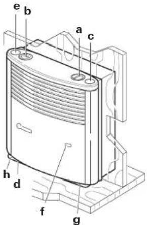
a = Control knob (Thermostat)
b = Dummy cover or Integrated control panel for Trumavent fan TEB / TEN
c = Automatic ignition (Trumatic S 3002 P model) or Dummy cover (Trumatic S 3002 model)
d = Automatic ignition device with battery compartment (model Trumatic S 3002)
e = Remote ignition display (accessory)
f = Window to check flame
g = Thermostat sensor
h = Data plate (remove front case!)
In the case of left-handed installation, the parts are arranged on the other side.
Trumatic S 5002 Heater
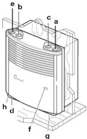
a = Control knob (Thermostat)
b = Dummy cover or Integrated control panel for Trumavent fan TEB / TEN
c = Dummy cover or Integrated control panel for second Trumavent fan TEB/TEN
d = Automatic ignition device with battery compartment
e = Remote ignition display (accessory)
f = Window to check flame
g = Thermostat sensor
= Data plate (remove front case!)
In the case of left-handed installation, the parts are arranged on the other side.
Trumatic S 5002 Heater and front case with flame effect
The flame effect and the Trumatic S 5002 heater can started up together or separately.
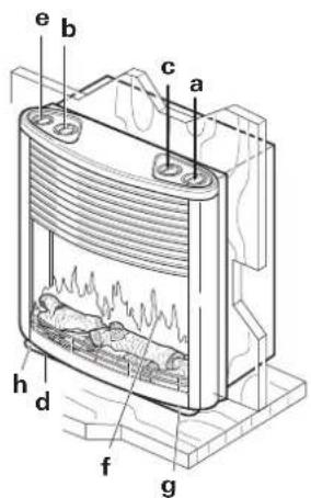
a = Control knob (Thermostat)
b = Dummy cover or Integrated control panel for Trumavent fan TEB / TEN
c = Dummy cover or Integrated control panel for second Trumavent fan TEB / TEN
d = Automatic ignition device with battery compartment
e = Control panel flame effect
f = Window to check flame
g = Thermostat sensor
h = Data plate (remove front case!)
In the case of left-handed installation, the parts are arranged on the other side.
Taking into operation with the piezo ignitor (Trumatic S 3002 P only)
- Turn on gas cylinder and open quick-acting valve in the gas supply line.
- Turn control knob (a) to thermostat setting 1-10 and press it down as far as the stop. At the same time keep operating the piezo ignitor rapidly until the flame ignites.
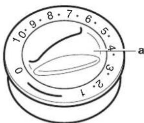
- Keep the control knob pressed down for a further 10 seconds to allow the safety pilot to operate.
- Observe through the in spction window for a further 10 seconds so as to check that the flame has not been extinguished due to air in the line (caused by a change of gas cylinder).
Wait for 2 minutes before re-igniting, otherwise risk of misfiring! This also applies if a working heater goes out and has to be re-lit.
If air has got into the gas line, it may take up to two minutes before gas is available for combustion. During this period, the operating handle should be kept pressed down and the pressure igniter constantly actuated until the flame appears.
- To ensure even and rapid warm air distribution as well as lower surface temperatures on the heating unit, we recommend that you operate the heater with a running Trumavent warm air system.
The Trumatic S 3002 P heater (with automatic ignition) is designed such that an auto ignitor with a remote ignition display can be retrofitted without problems (retrofit kit ZAS, part no. 30040-65700).
Taking into operation with the automatic ignitor (Trumatic S 3002 / S 5002)
Before using the heater for the first time, ensure that a battery has been inserted (see "Changing the battery")!
-
Turn on gas cylinder and open quick-acting valve in the gas supply line.
-
Turn control knob (a) to thermostat setting 1-10 and press it down as far as the stop. Ignition takes place automatically (ignition sparking audible) until the flame ignites.
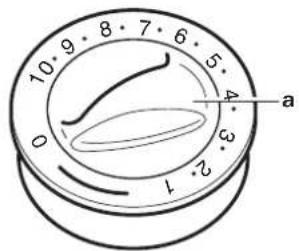
Keep the control knob pressed down for a further 10 seconds to allow the safety pilot to operate.

In the event of a fault always wait 2 minutes before attempting to reignite!
If the flame goes out again, re-ignition occurs immediately during the closing time of the safety pilot (approx. 30 seconds).
If there is no flame, the automatic ignitor continues to operate until the control knob (a) is switched to "0".
If there is air in the gas supply line, it can take up to two minutes until there is gas available for combustion. During this time hold the control knob down until the flame lights.
- To ensure even and rapid warm air distribution as well as lower surface temperatures on the heating unit, we recommend that you operate the heater with a running Trumavent warm air system.
The Trumatic S 3002 and S 5002 heating systems (with automatic igniters) can be fitted subsequently with a remote ignition indicator (e - part no. 30040-65400) with no trouble at all.
If the Trumatic S 5002 heater is combined with front case with flame effect it is not possible to have a remote ignition indicator.
Room thermostat
An average room temperature of about 22^ can be achieved without blower operation with a thermostat setting of 3-5. For operation with blower, we recommend a thermostat setting of 4-8.
The exact thermostat setting must be determined in accordance with the design of the vehicle and the specific heating requirements.
The thermostat probe is underneath the heater. Please note that the thermostat will be adversely affected by cold draughts from refrigerator vents, gaps below doors, etc., or by a deep-piled carpet. Always be sure to avoid problems of this kind, otherwise satis factory temperature control cannot be guaranteed.
Switching off
Turn the control switch to "0" (the automatic ignition will switch off at the same time).
If the unit is not used for a relatively long period of time, close off the quick-action gate valve on the gas pipe and gas bottle.
Control panel flame effect (Trumatic S 5002 only)
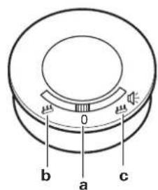
a = "Off"
(no flame effect, no sound)
b = Flame effect without sound
c = Flame effect with sound
(only flame effect in variant without sound effects)
Switching on
Move control panel switch to (b) flame effect without sound or (c) flame effect with sound.
Maintenance
In Germany, always notify the Truma Service Centre if problems are encountered; in other countries the relevant service partners should be contacted (see Truma Service Booklet or www.truma.com).

Attention: Despite careful manufacture, the heating system may contain sharp-edged components, and protective gloves should always be worn when carrying out any maintenance or cleaning work!

The electronics can be damaged by static discharges. Repairs may only be carried out by an expert!
Removing the front case
Pull the front case forward at the top, lift up the retaining springs and fold out case forwards. (If space is limited, lift the front case upwards and forwards, lift until the front case is released, then remove it.)
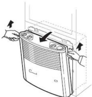
Then move the front case aside so that any connecting cables (e.g. for the Piezo-igniter, the warm air fan and the ignition indicator lamp or the open fire) do not have to be disconnected.
For assembly, place the front case on the lower retaining lugs (I). Guide the operating bar from below into the handle sleeve and allow the front case to engage at the top.
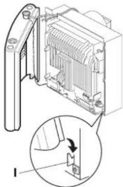
Trumatic S 3002 (P) only
Press the operating handle into position from above in such a way that the arrow points to the "0" position.
Changing battery on the auto ignitor
If no ignition sparking can be heard, or only at intervals of more than one second (or if the monitor lamp "e", a accessory, is not flashing), the battery needs to be replaced.
Replace the battery only if the heater is switched off. Insert a new battery before the start of the heating season! Dispose of old battery properly!
Remove the heater cover, push the battery compartment cover up and change the battery. Ensure that the polarity is correct. Close the battery compartment again.
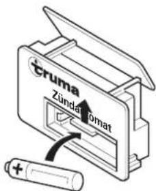
Only use temperature resistant (+70^) , leakproof Mignon batteries (LR 6, AA, AM 3, part no. 30030-99200), other batteries could cause operational faults!

Before scrapping the auto ignitor, remove battery and dispose of properly!
Cleaning (only when the unit is switched off!)
It is recommended that at least once a year, before the start of the heating season, the dust should be removed which may have collected on the heat exchanger, the baseplate, and the fan wheel of the Truma vent hot air system. Clean the fan wheel carefully with a dusting brush or small paintbrush.
Cleaning the front screen
(Trumatic S 5002, front case with flame effect)
Clean front screen window with lukewarm water containing a neutral cleaning agent. Use a soft sponge, woollen cloth or chamois leather. Never use sharp objects or solvent to remove stains.
Special instructions
- When the heater is being operated with a roof cowl, particularly when driving, cowl cover T3 (part no. 30700-03) must be used, and must be freely suspended in the air flow. A cowl extension AKV (part no. 30010-20800) must also be installed if necessary. This must be secured with a screw.
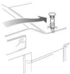
The camper manufacturer or heater installer must perform test drives to determine the combination of cowl top and extensions (if required) for the individual as delivered vehicle configurations and consult Truma if necessary. Depending on the vehicle model and the equipment installed on the roof, cowl top T1 (part no. 30700-01) or T2 (part no. 30700-02) may be required.
Roof extensions as well as luggage stowed in the vicinity of the exhaust cowl impede the heater in its operation, especially whilst the vehicle is moving. The flame may flash back, causing damage to the heater and vehicle. In this case additional cowl extensions must be used so that the top of the cowl projects at least 10cm above any objects. Failure to observe this instruction means that no guarantee claim will be entertained for resultant damage to the heater and vehicle.
- If the vehicle is undersealed, the combustion air intake connection under the vehicle must be covered to prevent the resulting spray mist from impairing the operation of the heating unit. Remove the covering again once the work is completed.
- In exceptional cases dust penetration etc. may occur. For these cases we recommend installing a sealing kit Trumatic S 3002 (P): part no. 30030-89800, Trumatic S 5002: part no. 30050-32700).
Disposal
The liquid gas heater must be disposed in accordance with the administrative stipulations of the respective country in which it is used. National regulations and laws (in Germany, for example, the Altfahrzeug-Verordnung - old vehicle directive -) must be observed.
In other countries, the relevant regulations must be observed.
Technical data
determined in accordance with EN 624 or Truma test conditions
Trumatic S 3002 (P), S 5002
Type of gas
Liquid gas (propane / butane)
Operating pressure
30 mbar (see data plate)
Rated thermal output
S 3002 (P): 3400 W
S 5002:5500 W
Gas consumption
S 3002 (P): 30 - 280 g/h
S 5002:60-480 g/h
Operating voltage
1.5V
Power consumption
50 mA (ignition)
0.01 mA (monitoring)
Weight
S 3002 (P): 9.8 kg (without fan)
S 5002: 17.5 kg (without fan)
S 5002 with front case with flame effect: approx. 19.5kg (without fan)
Front case with flame effect
Operating voltage
12V(DC/AC)
Power consumption with sound
0.65 A (DC) / 0.91 A (AC)
Power consumption without sound
0.63 A (DC) / 0.90 A (AC)
Fuse
1.25 AT (slow)
Weight
approx. 5.2kg
Declaration of conformity
The Trumatic S has been tested by the DVGW and complies with the gas equipment directive (90/396/EEC) and the other applicable EC directives. The following CE Product Ident. No. is available for EU countries
S 3002 (P): CE-0085AP0325
S 5002: CE-0085AP0326
The heater complies with heater directive 2001/56/EC and supplements 2004/78/EC and 2006/119/EC and bears the type approval number
S3002(P):e1000140
S 5002: e1 00 0141
The heater complies with the interference suppression directive 72/245/EEC for vehicle engines with annexes 2004/104/EC, 2005/83/EC and 2006/28/EC and bears type approval number:
e1032603
The heater complies with EMC directive 2004/108/EC and low voltage directive 2006/95/EC.
The heating system satisfies the End-of-Life Vehicle Directive 2000/53/EC.



The right to effect technical modifications is reserved!
Manufacturer's terms of warranty
1. Case of warranty
The manufacturer grants a warranty for malfunctions in the appliance which are based on material or production faults. In addition to this, the statutory warranty claims against the seller remain valid.
A claim under warranty shall not pertain:
- for parts subject to wear and in cases of natural wear and tear,
- as a result of not original Truma parts being used in the appliance and as a result of unsuitable gas pressure regulators being used,
- as a consequence of failure to respect Truma instructions for installation and use,
- as a consequence of improper handling,
- as a consequence of improper transport packing.
2. Scope of warranty
The warranty is valid for malfunctions as stated under item 1, which occur within 24 months after conclusion of the purchase agreement between the seller and the final consumer. The manufacturers will make good such defects by subsequent fulfilment, i.e. at their discretion either by repair or replacement. In the event of manufacturers providing service under warranty, the term of the warranty shall not re commence anew with regard to the repaired or replaced parts; rather, the old warranty period shall continue to run. More extensive claims, in particular claims for compensatory damages by purchasers or third parties, shall be excluded. This does not affect the rules of the product liability law.
The manufacturer shall bear the cost of employing the Truma customer service for the removal of a malfunction under warranty - in particular transportation costs, travelling expenses, job and material costs, as long as the service is carried out in Germany. The warranty does not cover customer service work in other countries.
Additional costs based on complicated removal and installation conditions of the appliance (e.g. removal of furniture or parts of the vehicle body) do not come under warranty.
3. Raising the case of warranty
The manufacturer's address is: Truma Geratetechnik GmbH & Co. KG, Wernher-von-Braun Strasse 12, 85640 Putzbrunn.
In Germany, always notify the Truma Service Centre if problems are encountered; in other countries the relevant service partners should be contacted (see Truma Service Booklet or www.truma.com). Any complaints are to be described in detail. In addition, the properly completed guarantee certificate is to be presented, or the factory number of the unit and the date of purchase given.
In order for the manufacturers to be able to determine whether an incident subject to guarantee has occurred, the end user must, at his own risk, bring the device to the manufacturers or send it to them. If there is damage to heaters (heat exchangers), the gas pressure regulator must also be sent back to the factory.
In instances of the device being sent to the works, dispatch is to be effected by freight transport. In cases under guarantee, the works shall bear the transport costs or the costs of delivery and return. If the damage is deemed not to be a warranty case, the manufacturer shall notify the customer and shall specify repair costs which shall not be borne by the manufacturer; in this case, the customer shall also bear the shipping costs.
h = plaque signalétique (retirer la façade !)
Trumatic S 3002 (P), S 5002
Type de gaz
Solo Trumatic S 3002 (P)
Trumatic S 3002 (P), S 5002
Tipodi gas
gas liquido (propano / butano)
S 3002 (P): CE-0085AP0325
S 5002: CE-0085AP0326
a = Bedieningshendel (thermostat)
g = Thermostatvoeler
Trumatic S 3002 (P), S 5002
Gassoort
S 3002 (P): CE-0085AP0325
S 5002: CE-0085AP0326
Trumatic S 3002 (P), S 5002
Gastype
Flydende gas (Prophan/Butan)
Driftstryk
30 mbar (se typeskilt)
Nominelvarmekapacitet
S 3002 (P): 3400 W
S5002:5500W
Gasforbrug
S 3002 (P): 30 - 280 g/h
S 5002: 60 - 480 g/h
Driftsspaending 1,5V
Strømforbrug
50 mA (taending)
S 3002 (P): CE-0085AP0325
S 5002: CE-0085AP0326
Los objetos sensibles al calor (p.ej. boles de spray) no deben depositarse en el espacio de montaje de la calefaction, ya queaquí las temperatasurasSEOSEOSEOSEOSEOSEOSEOSEOSEOSEOSEOSEOSEOSEOSEOSEOSEOSEOSEOSEOSEOSEOSEOSEOSEOSEOSEOSEOSEOSEOSEOSEOSEOSEOSEOSEOSEOSEOSEOSEOSEOSEOSEOSEOSEOSEOSEOSEOSEOSEOSEOSEOSEOSEOSEOSEOSEOSEOSEOSEOSEOSEOSEOSEOSEOSEOSEOSEOSEOSEOSEOSEOSEOSEOSEOSEOSEOSEOSEOSEOSEOSEOSEOSEOSEOSEOSEOSEOSEOSEOSEOSEOSEOSEOSEOSEOSEOSEOSEOSEO SEO
Trumatic S 3002 (P), S 5002
Tipodegas
gas liquido (Propano / Butano)
S 3002 (P): CE-0085AP0325
S 5002: CE-0085AP0326
GB In Germany, always notify the Truma Service Centre if problems are encountered; in other countries the relevant service partners should be contacted (see Truma Service Booklet or www.truma.com).
Having the equipment model and the serial number ready (see type plate) will speed up processing.