214334 - Remote control toy MULTIPLEX - Free user manual and instructions
Find the device manual for free 214334 MULTIPLEX in PDF.

| Product type | RC model (glider or motor glider) |
| Brand | Multiplex |
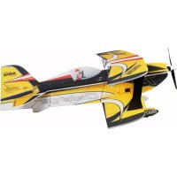
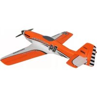
| Model | 214334 (FunRay) |
| Wingspan | 2000 mm |
| Overall length | 1230 mm |
| Flying weight | 1790 g |
| Wing area | 40 dm² |
| Wing loading | 45 g/dm² |
| Recommended power supply | LiPo 3S 3200 mAh battery (approx. 265 g) |
| Recommended motor | Brushless ROXXY C35-48-990 kv |
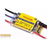
| Recommended speed controller | ROXXY BL-Control 755 S-BEC or Smart Control 70 MSB |
| Propeller | Folding propeller 11x7" (2 blades) |
| Servos | 6× HS-65HB Carbonite (ailerons, flaps, elevator, rudder) |
| RC functions | Elevator, rudder, ailerons, flaps, butterfly, motor, tow hook (glider version) |
| Center of gravity | 75 mm from wing leading edge |
| Main material | ELAPOR® foam with CFRP reinforcements and stainless steel |
| Minimum age required | 14 years (with adult supervision) |
| Safety | Liability insurance mandatory; avoid flying near people, animals, high voltage lines; check range and condition before every flight |
| Maintenance | Clean with a soft cloth; check glue joints and screws; store dry; use Zacki ELAPOR® glue for repairs |
| Spare parts | Available under reference numbers (e.g., wing, fuselage, canopy, cone, etc.); repairability ensured by manufacturer |
Frequently Asked Questions - 214334 MULTIPLEX
User questions about 214334 MULTIPLEX
0 question about this device. Answer the ones you know or ask your own.
Ask a new question about this device
Download the instructions for your Remote control toy in PDF format for free! Find your manual 214334 - MULTIPLEX and take your electronic device back in hand. On this page are published all the documents necessary for the use of your device. 214334 by MULTIPLEX.
USER MANUAL 214334 MULTIPLEX
natural_image
Model of a white and green funray propeller airplane with propellers, no visible text or symbols on the fuselage itself.FUNRAY

Bauanleitung
Abbildungen
Ersatzteile
2-15
37-44
15

Notice de construction 30-51
Illust rations
Building instructions 16-29
Illustrations
37-44
Replacement parts 29

Safety information for MULTIPLEX airplane models
When operating the model, all warning and safety information in the operating instructions must be observed.
The model is NOT A TOY in the conventional sense. If you use your model carefully, it will provide you and your spectators with lots of fun without posing any danger. If you do not operate your model responsibly, this may lead to significant property damage and severe injury. You and you alone are responsible for following the operating instructions and for ensuring the safety guidelines are adhered to.
When setting up the model, operators declare they are familiar with and understand the contents of the operating instructions, particularly regarding safety information, maintenance work, operating restrictions, and deficiencies.
This model may not be operated by children under the age of 14. If minors operate the model under the supervision of a responsible and competent adult pursuant to the law, this person is responsible for adhering to the information in the operating instructions.
THE MODEL AND THE ASSOCIATED ACCESSORIES MUST BE KEPT OUT OF REACH OF CHILDREN UNDER 3 YEARS OF AGE! CHILDREN UNDER 3 COULD SWALLOW REMOVABLE SMALL PARTS OF THE MODEL. RISK OF SUFFOCATION!
Multiplex Modellsport GmbH & Co. KG is not liable for loss, damage and consequential damage of any kind caused by incorrect operation, improper use or misuse of this product, including the accessories used along with it.
Proper use
The model may only be used in the hobby sector. No other type of use is permitted. To operate the model, only the accessories recommended by Multiplex may be used. The recommended components have been tested and adjusted for safe functioning together with the model. If other components are used or the model is modified, all claims against the manufacturer or retailer are void.
In order to minimize the risk when operating the model, observe the following points in particular:
- The model is controlled via a remote control. No remote control is safe from radio interference. Interference may lead to a loss of control of the model. Therefore, always ensure large safety distances in all directions when operating the model. As soon as even the smallest indication of radio interference presents itself, operation of the model must be halted immediately!
- The model may only be put into operation after a complete function and range test has been successfully carried out as per the instructions for the remote control.
- The model may only be flown in good visibility. Do not fly in poor light or in the direction of the sun in order to avoid glare.
-
The model may not be operated under the influence of alcohol or other intoxicants. The same applies for medicines that impair perception and responsiveness.
-
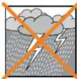
Only fly the model in wind and weather conditions in which you can safely control it. Even with light wind, take into account that turbulence may build up on objects and have an effect on the model.
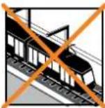
- Never fly in places where this would pose a danger to others, i.e. in residential areas, near power lines, roads, and railroad tracks.
- Never direct the model at people or animals! Avoid unnecessary risks and alert other pilots to potential hazards. Always fly in a manner that ensures neither you nor others are exposed to danger – even many years of accident-free flying experience are no guarantee for the next minute of flying time.


Residual risks
Even if the model is operated in accordance with the regulations and observing all safety aspects, there is always a residual risk.
Third-party liability insurance (powered model airplane) is therefore mandatory. If you are a member of a group or association, you might be able to take out the appropriate insurance there.
Ensure models and the remote control are properly maintained and are in good condition at all times.
Due to the construction and design of the model, the following dangers may arise in particular:
Injuries caused by the propeller: As soon as the battery is connected, the area around the propeller must be kept clear. Be aware that objects in front of the propeller may be sucked in and objects behind the propeller may be blown away. Always align the model ensuring it cannot move in the direction of other people if the motor starts up unintentionally. When performing adjustments for which the motor is running or may start up, the model must always be securely held in place by a helper.
- Crashes caused by control errors: Even the most experienced pilots can make mistakes. For this reason, only fly in a safe environment and at authorized model airplane flying fields.
- Crashes caused by technical failures, undetected damage from transportation or pre-existing damage: The model must be carefully inspected before each flight. Bear in mind that technical or material failures may occur at any time. Therefore, only operate the model in a safe environment.
- Adhere to operating limits: Excessively harsh flying weakens the structure of the model and may lead to technical and material failures as well as crashes immediately or, due to 'insidious' consequential damage, in later flights.
- Risk of fire due to malfunction of the electronics: Batteries must be stored safely. The safety information of the electronic components in the model, the battery, and the charging device must be observed.
Safety information for MULTIPLEX airplane models
The electronics must be protected from water. The controller and the batteries must be sufficiently cooled.
The instructions of our products may not be reproduced and/or published – not even in part – in print or electronic media without the express (written) permission of Multiplex Modellsport GmbH & Co. KG.
Safety information for MULTIPLEX construction kits
Familiarize yourself with the construction kit!
MULTIPLEX model kits are subjected to constant material inspection during production. We hope that you are satisfied with the contents of the kit. We nevertheless ask that you check all parts (according to the parts list) before use, as used parts cannot be exchanged. If a part is not OK, we will be happy to fix or replace it after verifying this. Please send the part with sufficient postage to our Service department. Be sure to include a short description of the fault along with the purchase receipt. We are continuously working on further developing the technology of our models. We reserve the right to make changes to the contents of the kit in terms of shape, dimension, technology, material, and equipment at any time and without warning. Please understand that no claims can be derived from specifications and illustrations in these instructions.
Caution!
Remote-controlled models, particularly airplane models, are not toys in the conventional sense. Their construction and operation requires technical understanding, a minimum level of artisan skills, discipline, and safety-awareness. Errors and negligences during building and operation may result in personal injury or property damage. As the manufacturer has no influence on proper assembly, maintenance, and operation, we explicitly refer to these dangers.
Warning:
Like any airplane, the model has static limitations! Nosedives and reckless maneuvers may result in damage to the model. Please note: In such cases, there is no replacement. Approach the limitations with caution. The model is fitted with the propeller recommended by us but can only withstand the loads if it is built flawlessly and is undamaged.
Crooked – does not really exist. If individual parts are bent during transit, they can be straightened again. Here, ELAPOR® behaves like metal. If you overbend the material slightly, it springs back minimally and retains its shape. The material of course has its limits – so don't overdo it!
Crooked – does indeed exist! If you want to paint your model, you do not need any primer for pretreatment when using the EC colors. Matt paints result in the best look. Under no circumstances may the paint coats be too thick or applied unevenly, otherwise the model will go out of shape and will be crooked, heavy or even unusable!
This model is not made of Styrofoam™! Therefore, adhesions using white glue, polyurethane or epoxy are not possible. These glues only stick superficially and may peel off in severe cases. Only use cyanoacrylate/ superglue of medium viscosity, preferably Zacki-ELAPOR® # 85 2727, the superglue optimized and adapted for ELAPOR® particle foam. When using Zacki-ELAPOR®, you can largely do without kickers or activators. If, however, you use other adhesives, and are unable to do without kickers/ activators, only spray outdoors for health reasons. Take care when working with all cyanoacrylate adhesives. These adhesives sometimes harden in seconds, so do not bring your fingers or other body parts into contact with them. To protect your eyes, be sure to wear protective goggles! Keep away from children! In some places, hot glue may also be used. If applicable, this is indicated in the instructions!
Working with Zacki ELAPOR®
Zacki ELAPOR® was developed specially for adhesion on our foam models made of ELAPOR®. In order to design the adhesion as optimally as possible, the following points should be taken into consideration:
- Avoid the use of activators. This causes the bonding to be significantly weakened. Especially for large-scale adhesion, we recommend allowing 24 hours for the parts to dry.
- Activators must only be used for point fixing. Only spray a little activator on one side. Allow the activator to flash off for approx. 30 seconds.
- For optimal bonding, sand down the surface using sandpaper (grain size 320).

text_image
ZACKi ELAPOR Slimiterer, Gb.Klebstahl ELSPOR® Partiker,Schäum ZACKi85 2727
Remote control elements in the model / other accessories / recommended equipment:
| MULTIPLEX receivers from RX-7-DR light M-LINK Order no. 5 5810 | |
| or RX-7 M-LINK (telemetry-capable) Order no. 5 5818 |
When using telemetry-capable M-LINK receivers, you can fit the model for instance with the Vario/height sensor, current sensor (electronic fuel gauge) or the G-sensor. A wide range of other sensors are available.
| ServoSet with cable set M6/UNI (complete) | 6x servo HS-65HB Carbonite1x cable set M6/UNI (for wing servos)2x servo extension cable 60 cm (for fuselage servos)2x plug fuse UNI | Order no. 1 -00113 |
| Drive set “FunRay” Brushless motor ROXXY C35-48-990kv, with fixing screwsController ROXXY BL Control 755 S-BECFlap propeller 11x7" (pair)Driver, spinner, and accessories are already included in the kit! | Order no. 1 -00103 | |
| Alternative (available individually) | 6x servo HS-65HB Carbonite (elevator+rudder+2x aileron+2x flap) Order no. 11 2065 | |
| 1x cable set M6/UNI FunRay (complete) Order no. 1 -00112 | ||
| 2x servo extension cable 60 cm (for fuselage servos) Order no. 8 5032 | ||
| 1x plug fuse UNI (SU 5 pcs.) Order no. 1 -00137 | ||
| Controller ROXXY Smart Control 70 MSB (with telemetry) Order no. 31 8579 | ||
| Battery recommendation | LiPo battery ROXXY EVO LiPo 3 - 3200M 30C (with M6 plug) ~265g | Order no. 1 -00482 |
| Adhesive Zacki ELAPOR ® 20g Order no. 59 2727 | ||
| Zacki ELAPOR® Super Liquid 10g | Order no. 59 2728 | |
| Hot glue, contact adhesive for canopy | ||
| Charger | HITEC multi charger X1 NANO | Order no. 30 8561 |
| POWER PEAK B6 EQ-BID | Order no. 11 4132 | |
| Tools | CutterSide cutterScrewdriver (for M3)Socket wrench WAF 13Hot glue gun | |
Specifications
| Wingspan | 2000 mm |
| Overall length | 1230 mm |
| Flying weight electric | 1790 g |
| Wing area (WA) | 40 dm ^2 (wing and elevator unit, without fuselage) |
| Wing loading | 45 g/dm ^2 |
| RC functions | Elevator, rudder, aileron, camber-changing flaps (flaps) => (butterfly), engine control or aero-tow release |
The center of gravity is 75 mm away from the front edge of the wing (hemispheres on the bottom).
Building instructions
Important
Remove image pages from the middle of the building instructions!
1. Before building
Check the contents of the kit.
The Fig. 1+2 and the parts list are helpful here.
2. Cutting the reinforcement belts to length - belts (GRP)
Using a side cutter, cut one of the fuselage-GRP rods 75 ∅2 x 700 mm in half in the middle (=> 2x 350 mm).
3. Sticking in the fuselage belts
For sticking, first apply some Zacki ELAPOR® into the recesses, then press the belts into the recesses, e.g. using a screwdriver, and apply Zacki ELAPOR® along the belts.
First stick in the two adapted fuselage belts 75 (350 mm) at the front on the inside of the groove of fuselage halves 3 and 4.
Stick the belt measuring 700 mm in length into the right fuselage half at the rear top into the groove in the back of the fuselage.
Fig. 3+4
4. Sticking in the locking clips
Stick the locking clips 22 right and left into the intended 'nests' of the fuselage halves.
Fig. 5 + 5.1
5. Controller attachment (holder for cable ties)
Stick the two holders 24 for the cable ties into the 'nests' of the right fuselage half. To do so, apply the adhesive so that it cannot escape through the flap openings to the outside.
Using the two cable ties 37, the controller will later be attached to the fuselage side.
Fig. 6
6. Electrical connection of the wing servos
In order to extend the servo cables and connect them to the fuselage, completely fabricated (soldered) cable sets with green MPX M6 high-current connectors are available under order no. #1-00112.
Info: The connection for this model takes place by means of a 'forced plug', i.e. the electrical connection of the servo cables is produced automatically when inserting the wings into the fuselage. This alleviates and shortens the assembly of the model and prevents the sockets from becoming mixed up and in so doing improves safety.
7. Preparing the M6 plug holder
Allow the fuselage-side cable harness (both connection cables are the same length here) to click into place with the edge of the green sockets in
the locking tabs of the plug holder 55. From the back (cable side) with two hot glue points, fix the connector/cable unit to the plug holder and press fully and straight into the recess until cool.
Fig. 7
8. Sticking in the M6 plug holder
Stick the M6 plug holder 55 into the intended recess of the right fuselage half. Feed through the cables between the holder and the fuselage side forward and downward and, using some masking tape, fix in place on the right fuselage half near the plugs.
Fig. 8
9. Preparing the fuselage servos
Now use the remote control or a servo tester to set the two servos for elevator and aileron to neutral and then mount the servo arms at right angles (90°) to the servo housing.
Caution: Due to the uneven number of teeth, the servo arms are not exchangeable by 180^ exactly. Therefore, be sure to adjust / mount the arms on the servo first, and only then shorten them inversely.
10. Shortening the servo arms (elevator and rudder)
For both servos, the double arms are cut off on one side. This can be done most effectively using a small side cutter. Position the servos alongside one another and first cut the left and then the right arm evenly. At the resulting cut surface, cut off another two 'corners' 45° to ensure the arm does not touch the housing of the servo holder 56 after the servo has been fitted.
11. Sticking the servos into the servo holder
Stick the two servos, with the arm forward, into the servo holder ^56 . On the servo holder 'behind' the servo, set a hot glue point in the middle and immediately press the servo into position. After this, set two hot glue points on the flaps of the servos from below – ideally, the adhesive will go into the center bore holes of the servo flaps (interlocking bonding).
Fig. 9
12. Mounting and securing the extension cables
Connect the servo cables to the 600 mm extension cables (contained in #1-00112 and #1-00113).
Secure the plug connection with the enclosed plug fuse (optional # 1-00137 SU 5 pcs.).
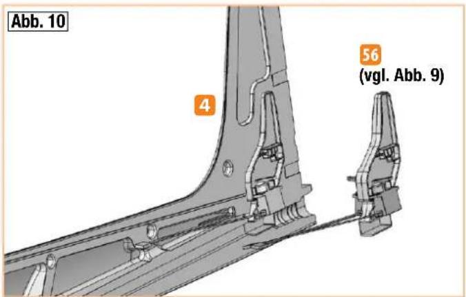
13. Sticking in the servo holder
Stick the prepared servo holder 56 with the two servos into the right fuselage half - feed the servo cables forward through the semicircular recesses and secure in the grommets using a little masking tape.
The servo/extension cables are subsequently laid loosely in the fuselage cable shaft – allowing the servo or undercarriage to be replaced if necessary.
Fig. 10

Building instructions
14. Rudder hinges
Stick the three recessed hinges 62 (pin support) into the right fuselage half.
Fig. 11
15. Fuselage reinforcement tube
The underside of the fuselage is reinforced with the carbon-fiber square tube 68 from the bulkhead up to the servo tail unit retainer 56. Mark the insertion depth (approx. 18mm) on the bulkhead.
Fig. 12
16. Sticking in the bulkhead and the reinforcing tube
Hint: The motor can already be screwed into the bulkhead now, as this is easier for handling.
Motor cable in direction of flight at the bottom right!
Then coat all the adhesive surfaces for the bulkhead 50 and the reinforcement tube 68 in the right fuselage half with viscous Zacki ELAPOR® - not forgetting the back in the retainer of the servo holder, too 56. Apply adhesive to the reinforcement tube 68 at one end and insert the tube approx. 18 mm into the square recess of the bulkhead 50 - now press this entire unit immediately into the right fuselage half. Ensure that the tube and the bulkhead are completely flush with the foam and the fuselage is not bent. Now at the rear, apply more adhesive to the servo holder/CFRP tube from the outside. Between the servo holder and the CFRP tube, some distance remains in order to compensate length tolerances of the foam caused during production.
Fig. 13
Before bonding it to the second fuselage half, check again that the cables are in the grommets properly and cannot become stuck to the fuselage.
17. Sticking the fuselage halves together
Proceed with caution here – this is an important step to build the model successfully.
Sand down the adhesive surfaces carefully using 320 sandpaper. First fit the fuselage halves together without adhesive. The fuselage must fit together without any force – rework wherever necessary.
Apply viscous Zacki ELAPOR® to the adhesive surface of one fuselage half – at a certain distance to the outer edge – and fit the fuselage halves together immediately. Ensure they are precisely aligned.
Keep the fuselage pressed together gently and straight for a few minutes. Do not carry out any bending or loading tests. The CA glue takes a few hours to reach its final strength.
Fig. 14
18. Fuselage end piece
Stick the two halves of the fuselage end piece 5 + 5 together. After weighing the model, stick the fuselage end piece to the fuselage tail.
Fig. 15
19. Completing the rudder
Stick the three recessed hinges 61 (pin) into the rudder 11. Behind this, stick in the rudder reinforcing tube 71 (200 mm) and cover it with the fully glued rudder cover 12. Make sure that no glue gets onto the hinge pins.
Fig. 16
Stick in the rudder horn 26 positioned forward, screw the hexagon socket set screw 28 into the cardan bolt 27 and fit into the outer holes.
Fig. 17
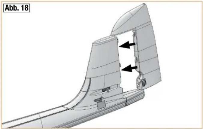
20. Mounting the rudder and connecting the rod
Position the rudder with the hinge pins precisely on the pin supports and lock into place in the fuselage by pressing forcefully from behind.
Fig. 18
Hook the rudder rod 33 (85 mm) from below into the outermost hole on the servo arm, bring the servo and the rudder into the neutral position, and clamp the rod in the cardan bolt.
Fig. 19
Hint: To release and remove the rudder, first release the rod by loosening the clamping screw, then swing it out as far as it will go to the right, and move it a bit further until it pops out of the hinges.
Electric version with propeller / glider version
With the brushless propulsion set 'FunRay' # 1-00103, the electric version of the model is ideally motorized.
The components in our drive set are compatible with one another and have been fully tested. If you use other batteries, controllers, motors or remote control components, you do so at your own discretion. However, in this case it is not possible for us to provide any service.
Alternatively, the model can be built as a glider. To do so, the optionally available glider nose # 22 4350 is stuck to the fuselage tip. In addition, the aero-tow release # 72 3470 can be fitted for aero-tows. This is, for instance, coupled with a 3/2 mm Bowden cable tube and a 1 mm steel wire.
21. Fitting the motor (from propulsion set # 1-00103)
Insert the motor with the cables into the bottom right of the bulkhead 50. Screw the motor onto the bulkhead using the four screws and the washers.
Fig. 20
Attach the controller and check the direction of rotation in conjunction with your remote control (still without the propeller). If you look at the front of the motor, the drive shaft must rotate counter-clockwise. If this is not the case, swap two of the three motor connections.
Caution: Do not connect the drive battery connector plug / controller until your transmitter is switched on and you are sure the operating element for the motor control is set to 'OFF'.
Secure the controller with a little adhesive tape (thin strips) or a hot glue point in the shaped position. Tie the cables using two cable ties 37 to the
Building instructions
brackets 24 and secure the connection cable to the fuselage side with a little hot glue. The cables are fed forward to the motor under the cross bar – be sure to fix the cables to the fuselage side near the motor with hot glue.
22. Mounting the spinner and the propeller
First screw the propeller blades (in the propulsion set #1-00103 or 1 pair of #1-00106) using the cylinder head screws 85 (M3 x 20 mm) and the stop nuts 86 onto the propeller driver 90. Tighten the screws until the propeller blades no longer have any play but can still be retracted slightly; if necessary adjust the propeller driver.
Now insert the pre-assembled propeller driver on the collet chuck 89 as shown. Then slide the entire assembly onto the motor shaft and ensure the propeller driver remains approx. 1 mm away from the fuselage. First mount the washer of the driver, then the washer 82 and the lock washer 83, and finally tighten the nut (M8) 84. Make sure the distance between the propeller driver and the fuselage remains the same while tightening! The spinner 91 is affixed with the screw 87 M2.5 x 12 mm. Fig. 21
Completing the elevator units
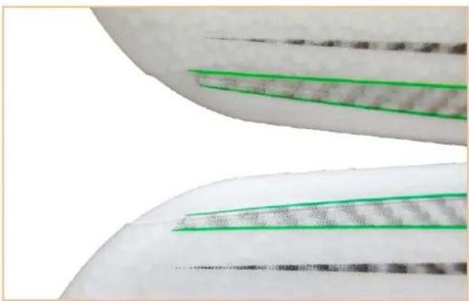
23. Sticking the leading edges to the elevator units
The leading edges 46 for the elevator unit halves 7 + 8 are symmetrical and can be stuck either on the left or right. To do so, place the elevator unit halves on the table so that the front part protrudes over the edge of the table. Now draw continuous 'tracks' with Zacki ELAPOR® on both sides, inside the leading edge, approx. 2 mm away from the edge. Position the hollow needle of the adhesive on the opposite edge to the guide and apply adhesive in a straight line. Apply less adhesive toward the outside. Position the leading edge from the outside flush on the tail unit and press on it for a while. If necessary, carefully remove any escaping glue. Do the same with the other half of the tail.
Fig. 22
24. Sticking in the elevator unit wing roots and the struts
Test-fit the left elevator unit wing root with the catch 57, the right elevator unit wing root 58, and two elevator unit strut tubes 74 analogous to the recesses in the left and right elevator unit 7 + 8. If everything fits, carefully stick these parts on all contact surfaces to the foam part. Make sure the struts are fully pressed into the slits in the foam and no glue gets into the area in which the struts of the other half will later have to be inserted. At these points, use the glue more sparingly.
Caution: Do not stick the elevator halves together until you have made sure that the glue has fully hardened. This may take several hours.
25. Making the rudder hinges accessible
Move the elevator flaps up and down several times in order to make the hinges smoother.
Stick the left elevator unit reinforcement tube 72 (200 mm) into the groove of the left elevator connector 59 and press it into the foam while positioned flat.
Likewise, stick the right elevator unit reinforcement tube 73 (120 mm) into the right elevator connector with the horn 60.
Caution: Do not apply any adhesive to the outer and inner sides of the plug square.
Fig. 22
26. Affixing the elevator unit to the fuselage
After ensuring the glue has hardened, test-stick the elevator halves 7 + 8 to the fuselage and allow the locking tab to lock into place – adjust if necessary. Remove the elevator unit again.
Fig. 23
To optimize the stability from the outside, re-stick, if necessary, the CFRP struts and the stainless steel tubes to the foam with a bit of Zacki ELAPOR® and put aside until fully hardened. Fix the ends with a bit of hot glue as well.
27. Preparing the elevator linkage
Mount the safety O-ring 38 to the rudder horn 60 so that it is positioned behind the four retaining collars.
Screw the hexagon socket set screw 28 into the cardan bolt 27.
Mount the cardan bolt in the outer holes of the rudder horn 60 on the elevator.
Caution: Only bend the rudder horn apart until the cardan bolt can be inserted. If you bend it too far apart, the horn may break off! Never use, e.g., a large screwdriver here as leverage!
28. Connecting the elevator rod
Test-fit the elevator unit to the fuselage.
Hook the elevator rod 32 (80 mm) from above into the second hole from the inside on the servo arm, bring the servo and the rudder into the neutral position and clamp the rod in the cardan bolt.
Fig. 24
Caution when disassembling the elevator unit: First release the rod by loosening the clamping screw. Then rotate the servo arm forward - feed the rod out of the cardan bolt and then release the elevator halves again by disengaging the self-locking mechanism. This is the only way to ensure the fuselage is not damaged by the cardan bolt.
Hint: Depending on the stress in rough terrain, the elevator hinges may tear from the outside over time. In this case, they can be reinforced with PVC hinges order no.: 70 3202 (6 pcs.).
To mount the PVC hinges, use a cutter to cut a suitable slit from the wing tip in the hinge progression and then stick in the PVC hinge with a little glue. The pivot must be on the hinge line.
29. Strut tubes in the wings
The high-strength struts are made of carbon fiber material (CFRP) coated with a precision drawn aluminum tube.
The strut tubes 69 are already fitted in the wings, if necessary they should be slightly deburred on the protruding ends (sandpaper) to ensure the
Building instructions
struts can be securely inserted into the opposite fin when assembling the model.
30. Sticking the leading edges to the wings
From the wing tip, first stick on the outer leading edge segment 42/43. To do so, place the wings on the table so that the front area protrudes over the edge of the table. Now draw continuous 'tracks' of Zacki ELAPOR® on both sides, inside the leading edge, approx. 2 mm away from the edge. Position the hollow needle of the adhesive on the opposite edge to the guide and apply adhesive in a straight line. Position the leading edge from the outside on the wing and press on with your fingers for some time, sliding your fingers up and down. If necessary, remove any escaping glue. Proceed in the same manner with the inner leading edge segment 40/41.
Fig. 25
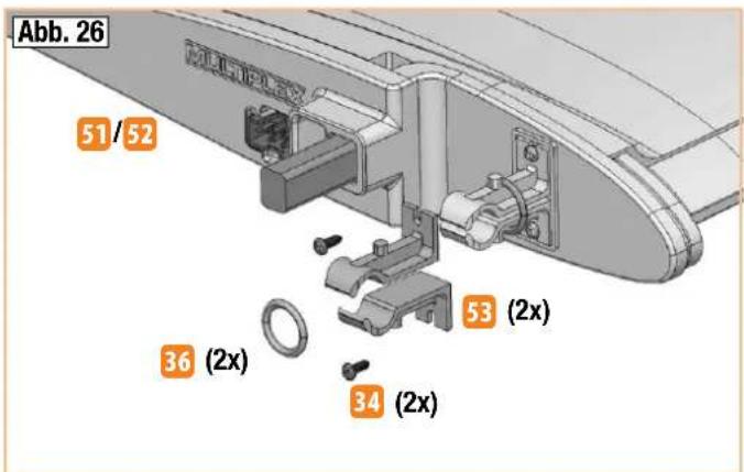
31. Mounting the wing roots / retaining clips
Affix the retaining clips 53 using the screws 34 to the left and right wing roots 51 and 52 inside the protruding border. Slide two 0-rings 36 8 x 2 mm over the retaining clips on each side so that they are pretensioned.
Fig. 26
32. Mounting the wing roots
Stick the wing roots 51 / 52 to the contact surfaces of the wings using Zacki ELAPOR®.
Press on the fins immediately with both hands forcefully and allow the glue to set.
Fig. 27
33. Affixing the leading edges to the transition segments
Stick the left and right leading edge filling pieces 44 and 45 to the wing roots and the leading edges.
To do so, apply a little glue slightly away from the edge on the inside of the filling piece and position before affixing. If necessary, remove any escaping glue.
Fig. 25
34. Reinforcing the ailerons and the flaps
Stick the stainless steel reinforcement tubes 70 (330 mm) into the corresponding longitudinal recesses of the wings (rudder flaps) (4x flat with CA adhesive). Fix the ends with a bit of hot glue as well.
Caution: At first, do not apply any glue in the area of the rudder horn indentations.
Fig. 28
35. Preparing and mounting the rudder horns
Screw the hexagon socket set screws 28 into the cardan bolts 27.
For the ailerons (QR), insert the cardan bolts into the outer holes of the rudder horns 26. When doing so, do not bend the tabs further open than necessary!
For the camber-changing flaps (WK), insert the cardan bolts into the
inner holes of the rudder horns 26. When doing so, do not bend the tabs further open than necessary.
CAUTION: Observe installation direction!
Aileron (QR) => armored forward
Camber-changing flap (WK) => arm oriented backward
Apply hot glue in the recesses and immediately insert the rudder horns 26 and press in fully - if necessary re-stick at the side.
Fig. 28+29
36. Cutting free the aileron and the camber-changing flaps
Cut the rudders free at the front sides using a cutter / backsaw and bend the rudder flaps up and down several times in order to make the hinges smoother. Under no circumstances may the rudders be separated from the hinge line!
37. Preparing the aileron servos
Caution: Due to the uneven number of teeth, the servo arms are not exchangeable by 180^ exactly. Therefore, be sure to adjust / mount the arms on the servo first, and only then shorten them inversely.
First position the servos electrically into the neutral position. Then mount the servo arm one tooth turned forward toward the housing (two servos mirror-inverted). This setting enables the mechanic differentiation of the ailerons. The differentiation is now mechanically attuned so that the rudder deflections upward are larger than downward.
In addition, the servo arms can be turned again by the same distance further out of the middle position (offset) using the transmitter. With this setting, you can achieve even larger deflections upward. As a result, even larger butterfly deflections can be achieved.
This is helpful for landing in confined spaces or ridge lifts.
Fig. 28
38. Preparing the camber-changing servos (flaps)
For the flap servos, the servo arms are turned into the neutral position one tooth turned backward toward the housing (two servos mirror-inverted). The possible deflection is enlarged downward as a result! Here, an offset can additionally be set on the transmitter – the rods are slightly longer in this case.
Fig. 29
39. Shortening the servo arms
For all four wing servos, the double arms are completely cut off on one side and shortened on the other. For shortening, cut precisely through the third hole from the inside so that the two inner holes can still be used. This can be done most effectively using a small side cutter. For this, cut off two left and two right / mirror-inverted arms after mounting on the servos. It is necessary to shorten them to ensure the servo hoods can be mounted later.
40. Fitting the aileron / camber-changing servos (flaps)
Insert hot glue into the slits for the servo flaps and immediately press the
Building instructions
servos into the recesses. If required, apply more glue into any remaining slits on the flaps. Then cut off any protruding hot glue flush and lay the servo cables.
41. Cable routing in the wing # 1-00112
Now guide the wing cables (with extensions of varying lengths) through the connector recesses of the wing roots toward the servo. Click the locking tab into place in the small recess of the green M6 connector so that it is almost flush with the fin. The connector can remain without cabling – thanks to the small play, tolerances to the fuselage plug are compensated.
Now connect the servo cable to the extensions and apply force from the servo to press them flush into the slits. The plug-in connectors go into the larger recesses. Keep the remaining cable loops in open spaces behind the wing root and, if necessary, secure with a little hot glue so that they do not protrude over the edge of the wings.
Finally, stick a matt, transparent, approx. 20 mm wide adhesive strip over the cables to secure them.
42. Mounting the rudder rods
Hook the aileron rods 30 (50 mm) with the 'Z' on the servo arm into the second hole from the inside.
Hook the flap rods 31 (60 mm) with the 'Z' on the servo arm into the second hole from the inside.
Guide the other ends through the cardan bolts of the rudder horns and tighten the socket set screws 28 in the cardan bolts 27 after carrying out the adjustment. For offset setting (transmitter), readjust the neutral position of the rudder flaps accordingly.
Fig. 28+29
43. Affixing the servo ducts
Affix the servo ducts 64 and 65 above the rods as shown in the illustration. To do so, stick the flaps into the slits.
Fig. 30+31
44. Canopies (EPP foam or transparent)
In the construction kit and for RR, the canopy 6 is made of robust, gray EEP. Consequently, you do not have to paint it and, after sticking down the brackets, it is quickly completed.
Hint: Optionally, a transparent canopy with cockpit is also available. This is available as a construction kit under order no.: 1-00138.
45. Completing the canopy (EPP)
Stick the canopy finger-grip 63 from beneath with hot glue into the canopy 6. Stick the two closure plugs 23 with the last serration flush into the holes / moldings in the canopy finger-grip. To do so, apply a little superglue into the slits and onto the edges and then insert the closure plugs into the slits. Make sure the brackets are parallel and at right angles in the molding on the canopy finger-grip — this is the only way to ensure they latch in on both sides and hold the canopy securely.
Fig. 32
46. Completing the transparent canopy
Optional construction kit order no. # 1-00138
For an appealing and authentic look, we recommend painting the canopy frame. You can get the best results with EC® COLOR. Paint, for instance, the frame, the instrument panel, and the seat gray # 60 2806. Once the paint is dry, stick on the labels for the instrument panel and the seat precisely.
Stick the two closure plugs with the last serration flush into the slits / moldings in the canopy frame. To do so, apply a little superglue into the slits and onto the edges and then insert the closure plugs. Make sure the brackets are parallel and at right angles in the molding on the canopy finger-grip – this is the only way to ensure they latch in on both sides and hold the canopy securely.
Stick the canopy glass, e.g. with transparent contact adhesive, to the canopy frame.
Do not allow the contact adhesive to flash off as usual; instead, apply the adhesive, immediately place the canopy on top, and fix into place with adhesive strips. Allow the adhesive to dry for some time. Use the adhesive sparingly so that the frame does not become stuck to the body; if necessary, lay a thin film between the body and the canopy frame.
Finally, the canopy frame can be taped, e.g. using elastic, dark gray adhesive tape.
Fig. 33
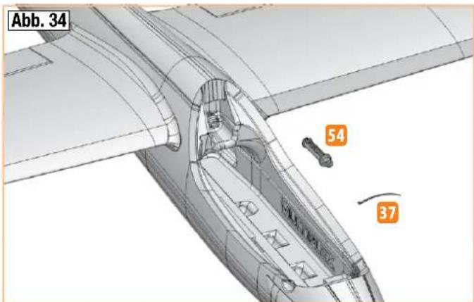
47. Preparing the retaining pin
On the retaining pin, 54 affix a cable tie 37 and only tighten to a large loop - shorten the protruding end flush so that it cannot be tightened further by accident. The loop will later be used to pull out the pin.
Fig. 34
48. Assembling the wings
Connect the wings fully to the fuselage. Fix them with the retaining pin 54 in the fuselage between the wings. To make sure the locking pin does not become lost, affix it with a string inside the fuselage.
Fig. 34
49. Mounting / removing the elevator unit
The elevator unit is secured to the fuselage with a self-locking mechanism. To open the mechanism, press the small flap forward on the underside and remove the tail unit (first unhook the elevator rudder rod).
Fig. 23
50. Final assembly
Affix the connected receiver using the enclosed adhesive tapes 20 and 21 to the fuselage underneath the closure plug.
There is a suitable molding for the antenna on the right half of the fuselage in the rear canopy cutout. Lay the antenna flush against the canopy edge and secure with an adhesive strip. For two antennas, guide the second one backward through the air outlet of the left half of the fuselage and secure with an adhesive strip.
Building instructions
51. Affixing the decals
The kit includes extensive decal sheets 2. The individual letterings and emblems have already been cut out and are affixed according to our template (construction kit picture) or as desired. For positioning, there are also several pictures in the building instructions. Cut out the large decals with a little excess together with the carrier paper – carefully remove circumferential waste (transparent) around the decal. Test position the decal on the surface on which it is to be glued. After this, pull off the carrier paper from the positioning location approx. 15 cm and cut off with the scissors – the retaining carrier paper stays for the time being.
Position the element at the desired location and align it on the surface with carrier paper. If everything fits, raise the decal slightly and slowly pull out the carrier paper, starting at the cut surface. Carefully smooth out the decal – do not rub immediately, only then can necessary corrections (deductions) be made. Be careful here to ensure the film is not stretched and still fits. Then rub firmly all over and without any bubbles using a soft cloth.
52. Affixing the landing skids
The kit includes two landing skids 13 made of robust special adhesive film. Stick them on at the front and back beneath the fuselage. Affix the large film directly behind the spinner in the middle on the fuselage joint while rubbing firmly toward the outside. Stick on the smaller film, starting approx. 10 mm away from the fuselage tail.
Hint: Transfer the center markings to the float body labels using a thin waterproof pen. This allows you to position the parts in the middle on the fuselage joint.
53. Mounting the battery
Use the adhesive tapes 20 and 21 as well as the adhesive attachment strap 25 to fix the battery securely in the model.
Feed the adhesive attachment strap through one of the three grommets at the front in the fuselage beneath the CFRP square tube. If the right position has been determined, fix the adhesive strips to the left and right on the CFRP tube.
54. Balancing out the center of gravity
In order to achieve stable flying qualities, your model, just like any other aircraft, must be in equilibrium at a certain position. Assemble your model, making sure it is ready to fly.
The center of gravity is marked 75 mm away from the front edge of the wings (hemispheres on the bottom). Using your fingers as support, pivot the model horizontally. Set the center of gravity by positioning the battery and, if necessary, by pushing in the trim weight 35 (sphere) into the fuselage tail. Due to material density tolerances and varying equipment variants (battery / transparent canopy) of the glider and the electric glider, no exact specifications can be made here. Trim weight may also be necessary in the fuselage nose - this can be attached in the space behind the motor - and secured into position using, e.g., hot glue. If the right position has been found, mark the fuselage accordingly to ensure the battery is always in the same position. Then close the trim weight opening at the fuselage tail by sticking on the fuselage end piece 5 / 5.1
Fig. 15
Hint: The center of gravity can be conveniently balanced using the center of gravity scale order no.: 69 3054.
55. Setting the rudder deflections (guidelines!)
To achieve a balanced control of the model, the size of the rudder deflections must be set correctly. The deflections are measured at the lowest point of the rudders.
Elevator
| Upward (joystick pulled back) approx. +15 mm | |
| Downward (joystick pushed forward) approx. - 15 mm | |
| Spoiler (elevator downward) approx. - 3.5 mm | |
| Electric version: Gas mixture at height 0 mm | |
| Flap mixture into elevator at speed / thermal | approx. - 1 / 0 mm |
Rudder
| To the left and right approx. 35 mm each |
Aileron
| Upward / downward approx. + 20 / - 9 | mm |
| Speed flight and aerobatic position (upward) approx. + 2.5 mm | |
| Thermal (downward) approx. - 2.5 mm | |
| Spoiler (aileron upward) approx. + 20 mm |
Flap (camber-changing flap)
| Horizontal transverse component (flap only upward) | approx. + 10 mm |
| Speed flight and aerobatic position (upward) approx. + 3.5 mm | |
| Thermal (downward) approx. - 3.5 mm | |
| Spoiler (flaps downward) approx. -27 mm | |
Spoiler (butterfly) / with additional transmitter - offset
| Both ailerons upward(20% transmitter - offset) | approx. + 28 mm |
| Both flaps downward(37% transmitter - offset) | approx. - 33 mm |
| Spoiler mixing at height approx. - 3.5 mm |
Caution: The strength of the model is very high – but it is not comparable with full GRP-CFRP models!
Speed flight and aerobatics always only in speed position of the ailerons and camber-changing flaps. Do not extend the butterfly at high speed – execute gliding arcs in an appropriate ratio to the speed! If you observe
Building instructions
this, you will have many hours of operating pleasure with your model.
For the 'spoiler' function, both ailerons are set upward and the flaps downward (butterfly or crow) to shorten the landing approach. At the same time, a corresponding hydroplane deflection is mixed in to keep the model in a stable flying condition. This requires a remote control with corresponding mixers.
To this end, always read the instructions of your remote control carefully!
The butterfly setting enables steep and accurate landing approaches even in difficult terrain.
Hint: Depending on the terrain (e.g. tall grass), we recommend retracting the battery again shortly before making contact with the ground to ensure the hinges and linkages are not strained / damaged.
Important: With the 'right' aileron, the aileron on the right looking in the direction of flight moves upward. At the same time,
the right flap moves halfway up with it. With downward aileron deflection, the flap does not move downward with it!
If your remote control does not permit the distances specified above, you might need to adjust the pushrod connector.
Make sure that all remote control components are fitted correctly and connected. Check the rudder settings, directions of rotation of the servos, and freedom of movement of the rudder mechanisms. Make sure the connection cables are nowhere near the rotating motor (secure with hot glue)! Check the motor rotation direction again (carefully!).
56. Preparations for the first flight
For the first flight wait for a day with as little breeze as possible; the evening hours often offer calmer conditions.
It is essential to carry out a range-check before the first flight! Please follow the instructions laid down by your RC system manufacturer.
The transmitter battery and flight pack must be fully charged in accordance with the manufacturer's recommendations. Before switching the system on, ensure that your chosen channel is free; this does not apply if you are using a 2.4 GHz system.
If you are unsure about any point, do not fly the model! If you cannot identify and cure the problem, send the whole RC system (including battery, switch harness and servos) to your system manufacturer for checking.
57. Maiden flight ...
The aircraft is designed to be hand-launched (always into wind).
If you are a beginner to model flying, we strongly recommend that you ask an experienced modeller to help you for the first few flights. Once the model has reached a safe height, adjust the control surfaces using the trims on the transmitter, so that the model flies straight and level "hands-off".
Powered version: with the aircraft flying at an adequate altitude, check how it responds when the motor is switched off, so that you are familiar with its behaviour on the glide. Carry out repeated simulated landing approaches at a safe height, as this will prepare you for the real landing when the battery is discharged.
Avoid flying tight turns at first, especially close to the ground, and in particular during the landing approach. It is always better to land safely some distance away than to risk a crash by forcing the model back to your feet.
58. Thermal flying
Making the best use of flat field thermals is not particularly easy, and calls for considerable skill and experience. Areas of rising air are harder to detect and recognise at a flat field, because they tend to occur at higher altitude than at the hillside, where it is often possible to find lift while the model is cruising along the edge of the slope, and then circle away in it. A thermal at a flat field which occurs directly overhead is very hard to recognise, and to exploit it to the full requires a highly skilled pilot. For this reason it is always best to go thermal seeking off to one side of where you are standing.
You will recognise thermal contact by the glider's behaviour. Good thermals are obvious because the model will climb strongly, but weak thermals take a practised eye to detect, and you will need a lot of skill to make use of them. With a little practice you will be able to recognise likely trigger points for thermals in the local landscape. The ground warms up in the sun's heat, but heat absorption varies according to the type of terrain and the angle of the sun's rays. The air over the warmer ground becomes warmer in turn, and the mass of warm air flows along close to the ground, driven by the breeze. Strong winds usually prevent thermal build-up. Any obstruction - a shrub or tree, a fence, the edge of a wood, a hill, a passing car, even your own model on the landing approach - may cause this warm air to leave the ground and rise. Imagine a drop of water on the ceiling, wandering around aimlessly, and initially staying stuck to the ceiling. If it strikes an obstruction it will fall on your head. A triggered thermal can be thought of as the opposite of the drop of water.
The most obvious thermal triggers include sharply defined snow fields on mountain slopes. The air above the snow field is cooled, and flows downhill; at the edge of the snow field, part-way down the valley, the cool air meets warm air flowing gently uphill, and pushes it up and away as if cut off by a knife. The result is an extremely powerful but bumpy thermal bubble. Your task is to locate the rising warm air and centre your model in it. You will need to control the glider constantly to keep it centred, as you can expect the most rapid climb rate in the core of the thermal. Once again, this technique does demand some skill.
To avoid losing sight of the machine be sure to leave the thermal in good time. Remember that a glider is always easier to see under a cloud than against a clear blue sky. If you have to lose height in a hurry, do bear the following in mind:
The structural strength of the Heron is very great for this class of model, but it is not infinite. If you attempt to destroy the model forcibly, please don't expect any sympathy or compensation from us (alas, we speak from experience).
59. Flying at the slope
Ridge soaring is an extremely attractive form of model flying. Soaring for hours on end in slope lift, without needing any outside aid for launching, must be one of the finest of modelling experiences. But to “milk” a thermal to the limits of vision, bring it down again in a continuous series of aerobatic manoeuvres, and then repeat the whole show - that must surely be the last word in model flying.
Building instructions
But take care - there are dangers for your model lurking at the slope. Firstly, in most cases landing is much more difficult than at a flat field site. It is usually necessary to land in the lee of the hill where the air is turbulent; this calls for concentration and a high-speed approach with last-minute airbrake extension. A landing on the slope face, i.e. right in the slope lift, is even more difficult. Here the trick is to approach slightly downwind, up the slope, and flare at exactly the right moment, just before touch-down.
60. Aero-towing
An ideal combination for learning to aero-tow, and for actual aero-towing, is a FunCub and a Heron.
For the tow you require a 20 m length of braided cable of 1 to 1.5 mm ∅. Tie a loop of nylon line (0.5 mm ∅) to the glider end of the cable; this acts as a "weak link", in case the tow should go badly wrong.
A loop in the other end of the towline should be connected to the aerotow coupling of the FunCub. Assemble the models, connect them as described, and set them up directly into wind, the glider behind the tug. Check that the towline is resting on top of the FunCub's tailplane. The tug now rolls forward until the towline is taut, and only then should the tug's pilot apply full-throttle. Both aeroplanes accelerate: the tug stays on the ground initially, while the glider lifts off, but the glider pilot keeps his model flying low above the ground, directly in the wake of the tug; the tug can now lift off safely. The two models should be kept climbing steadily, even through turns. Avoid flying directly over your heads during the first few attempts at aero-towing, as it is difficult to detect the models' attitudes from this angle. To drop the tow, operate the transmitter control which opens the tow release mechanism.
61. Electric flying
With the electric version you have the optimum level of autonomy and independence. You can fly from a flat field and carry out about seven climbs to a sensible gliding height (around 150 m) from a single battery charge. At the slope you can also keep the electric power system as a "lifebelt", i.e. you only use the motor to "keep afloat", and avoid landing out, i.e. landing at the bottom of the slope when the lift fails.
62. Flight performance
What is meant by a glider's performance?
The two most important parameters are sinking speed and glide angle. Sinking speed is a measure of the vertical height lost per second relative to the surrounding air. The sinking speed is primarily determined by the wing loading (weight relative to wing area). Here the Heron offers a really excellent performance - much better than conventional models - as its wing loading is so low. This means that only slight thermal assistance is necessary (warm air rising) to cause the model to gain height. Wing loading is also the main factor in determining the model's airspeed - the lower the loading, the slower the model. Low airspeed means that the model can be turned extremely tightly, and this is also advantageous when thermal flying, as areas of lift are usually very small when close to the ground.
The other important parameter in glider performance is the glide angle. This is stated as a ratio, i.e. from a particular altitude the model flies such and such a distance. The glide angle increases as wing loading rises,
and at the same time - of course - the model's airspeed increases. This becomes necessary if you wish to fly in relatively strong winds, and when you need "energy retention" for flying aerobatics.
For thermal flying you need a good glide angle too, as this is the key to flying across areas of "sink" (the opposite of a thermal) quickly, so that you can seek out another thermal.
63. Safety
Safety is the First Commandment when flying any model aircraft. Third party insurance is mandatory. If you join a model club, suitable cover will usually be available through the organisation. It is your personal responsibility to ensure that your insurance is adequate (i.e. that its cover includes powered model aircraft). Make it your job to keep your models and your radio control system in perfect order at all times. Check and observe the correct charging procedure for the batteries you are using. Make use of all sensible safety systems and precautions which are advised for your system. An excellent source of practical accessories is the MULTIPLEX main catalogue or our website www.multiplex.de
MULTIPLEX products are designed and manufactured exclusively by active modellers for practising modellers. Always fly with a responsible attitude. You may think that flying low over other people's heads is proof of your piloting skill; others know better. The real expert does not need to prove himself in such childish ways. Let other pilots know that this is what you think too, as it is in all our interests. Always fly in such a way that you do not endanger yourself or others. Bear in mind that even the best RC system in the world is subject to outside interference. No matter how many years of accident-free flying you have under your belt, you have no idea what will happen in the next minute.
Before every flight, check that the battery, the wings and the tailplane are attached and firmly seated. Check in turn that each control surface is operating correctly!
We - the MULTIPLEX team - hope you have many hours of pleasure building and flying your new model.
| Seq. no. Qty. Name Material Dimensions | ||||
| 1 1 Building instructions KIT Paper | ||||
| 1.1 1 Complaints regarding models Paper | ||||
| 2 1 Decal sheet Printed adhesive film 700 x 1000 mm | ||||
| 3 1 Left fuselage half Foamed Elapor Finished component | ||||
| 4 1 Right fuselage half Foamed Elapor Finished component | ||||
| 5 1 Left fuselage end piece Foamed Elapor Finished component | ||||
| 5.1 1 Right fuselage end piece Foamed Elapor Finished component | ||||
| 6 1 Canopy | Foamed EPP | Finished component (gray) | ||
| 7 1 Left elevator unit | Foamed Elapor Finished component | |||
| 8 1 Right elevator unit | Foamed Elapor Finished component | |||
| 9 1 Left wing | Foamed Elapor Finished component | |||
| 10 | 1 Right wing | Foamed Elapor Finished component | ||
| 11 | 1 Rudder | Foamed Elapor Finished component | ||
| 12 | 1 Rudder cover | Foamed Elapor Finished component | ||
| 13 | 1 | Landing skid front + back FunRay | Special – adhesive film | Finished component |
Set of small parts
| Seq. no. Qty. Name Material Dimensions | ||||
| 20 | 2 | Mushroom head adhesive tape | Plastic | 25 x 60 mm |
| 21 | 2 | Velour adhesive tape | Plastic | 25 x 60 mm |
| 22 | 2 Locking clip | Injected plastic Finished component | ||
| 23 | 2 Closure plug | Injected plastic Finished component | ||
| 24 | 2 | Holder for cable ties | Plastic | 12 x 30 mm |
| 25 | 1 | Fastening strap for battery | Plastic | 16 x 200 mm |
| 26 | 5 | Rudder horn 'twin' pipe joint | Injected plastic | Finished component |
| 27 | 6 | Cardan bolt | Metal | Finished component ∅6 mm |
| 28 | 6 | Hexagon socket set screw | Metal | M3 x 3 mm |
| 29 | 1 Hex key | Metal | WAF 1.5 | |
| 30 | 2 | Aileron rod with accessories | Metal | ∅1 x 50 mm |
| 31 | 2 | Camber-changing flap rod with accessories | Metal | ∅1 x 60 mm |
| 32 | 1 | Elevator rod with accessories | Metal | ∅1 x 80 mm |
| 33 | 1 | Rudder rod with accessories | Metal | ∅1 x 85 mm |
| 34 | 4 | Screw (retaining clip) | Metal | 2.2 x 6.5 mm |
| 35 | 1 | Trim weight (if required) | Metal sphere | ∅15 mm / 13.8 g |
| 36 | 4 | O-ring (locking clip) | Plastic | 8 x 2 mm |
| 37 | 3 Cable tie | Plastic | 98 x 2.5 mm | |
| 38 | 1 | O-ring (elevator unit rudder horn) | Plastic | 6 x 1 mm |

Parts list KIT FunRay # 21 4334
Leading edge set
| Seq. no. Qty. Name Material Dimensions | ||
| 40 1 Inner left leading edge Injected plastic Finished component | ||
| 41 1 Inner right leading edge Injected plastic Finished component | ||
| 42 1 Outer left leading edge Injected plastic Finished component | ||
| 43 1 Outer right leading edge Injected plastic Finished component | ||
| 44 1 Left leading edge filling piece Injected plastic Finished component | ||
| 45 1 Right leading edge filling piece Injected plastic Finished component | ||
| 46 2 Elevator unit leading edge Injected plastic Finished component |
Plastic parts set
| Seq. no. Qty. Name Material Dimensions | ||||
| 50 1 Motor bulkhead with flange Injected plastic Finished component | ||||
| 51 1 Left wing root | Injected plastic Finished component | |||
| 52 1 Right wing root | Injected plastic Finished component | |||
| 53 4 Retaining clip | Injected plastic Finished component | |||
| 54 1 Retaining pin | Injected plastic Finished component | |||
| 55 1 M6 fuselage plug bracket | Injected plastic Finished component | |||
| 56 1 Servo holder fuselage | Injected plastic Finished component | |||
| 57 1 Elevator unit left wing root with catch | Injected plastic Finished component | |||
| 58 1 Elevator unit right wing root | Injected plastic Finished component | |||
| 59 1 Left elevator connector | Injected plastic Finished component | |||
| 60 1 Right elevator connector with horn | Injected plastic Finished component | |||
| 61 3 Recessed hinge pin | Injected plastic Finished component | |||
| 62 3 Recessed hinge pin support | Injected plastic Finished component | |||
| 63 1 Canopy finger-grip | Injected plastic Finished component | |||
| 64 2 Left servo hood | Injected plastic Finished component | |||
| 65 2 Right servo hood | Injected plastic Finished component | |||
Reinforcements (pipes and rods)
| Seq. no. Qty. Name Material Dimensions | ||||
| 68 1 Fuselage reinforcement tube CFRP square 10 x 8.4 x 1010 mm | ||||
| 69 2 Strut tube => fitted in the wing ALU-CFRP square 10 x 8 x 822 mm | ||||
| 70 | 4 | Aileron and camber-changing flaps reinforcement tube | Stainless steel tube | ∅3 x ∅2.6 x 330 mm |
| 71 | 1 | Rudder reinforcement tube | Stainless steel tube | ∅3 x ∅2.6 x 200 mm |
| 72 | 1 | Left elevator unit reinforcement tube | Stainless steel tube | ∅3 x ∅2.6 x 200 mm |
| 73 | 1 | Right elevator unit reinforcement tube | Stainless steel tube | ∅3 x ∅2.6 x 120 mm |
| 74 2 Elevator unit strut tube CFRP square 5.5 x 3.5 x 200 mm | ||||
| 75 2 GRP rod GRP ∅2 x 700 mm | ||||
Parts list KIT FunRay # 21 4334
Spinner/driver set
| Seq. no. Qty. Name Material Dimensions | ||
| 82 1 Washer Metal ∅ 8.4 mm | ||
| 83 1 Lock washer Metal ∅ 8.4 mm | ||
| 84 1 Nut Metal M8 | ||
| 85 2 Cylinder head screw Metal M3 x 20 mm | ||
| 86 2 Stop nut Metal M3 | ||
| 87 1 Oval countersunk head screw Metal M2.5 x 12 mm | ||
| 89 1 Collet chuck (complete) Metal ∅d 5 mm | ||
| 90 1 Propeller driver Injected plastic Finished component | ||
| 91 1 Spinner Injected plastic Finished component |

Replacement parts KIT FunRay # 21 4334
| Art. no | Description |
| 1-00121 | Fuselage, assembled (excl. RC + decals) |
| 1-00122 | Rudder, completed (excl. decals) |
| 1-00123 | Canopy and latch |
| 1-00124 | Wing set, completed (excl. RC + decals) |
| 1-00125 | Tailplane, completed (excl. decals) |
| 733183 Spinner, propeller driver, taper collet, complete | |
| 1-00106 | 2 folding propeller blades, 11 x 7" |
| 1-00126 | Decal sheet |
| 1-00127 | "FunRay" control surface horn, 12 x 20 with connector, 2 sets |
| 1-00128 | O-ring, 8 mm ∅ (pack of 4) |
| 1-00129 | O-ring, 6 mm ∅ (pack of 2) |
| 1-00130 | Retaining pin |
| 1-00131 | Small parts set |
| 1-00132 | Plastic parts set, wings |
| 1-00133 | Plastic parts set, fuselage + tail |
| Art. no. | Description |
| 1-00134 | Tubes and GRP rod |
| 1-00135 | Leading edge set |
| 1-00136 | Square CFRP tube, 10 x 10 x 1010 mm |
| 1-00407 | Servo fairing, 1 pair |
| 725136 Canopy lock (pack of 2) | |
| 1-00137 | UNI connector retainer (pack of 5) |
| 112065 HS-65HB servo | |
| 315076 ROXXY C35-48-990kv motor | |
| 318975 ROXXY BL-Control 755 S-BEC speed controller | |
| 1-00371 | Clear plastic film landing skids (front and rear) |
| 1-00112 | FunRay cable set (complete) |
| 85032 | Extension lead, 60 cm (for fuselage servos) |
| 224350 Glider fuselage nose (for glider version) | |
| 723470 Tow-release (for glider version) | |
For further information about the contents of the replacement parts, please visit www.multiplex-rc.de
natural_image
3D CAD model of a boat hull with structural components and an arrow indicating a specific part (no text or symbols present)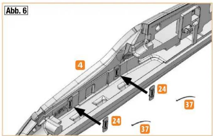
text_image
Abb. 6 4 24 37 24 37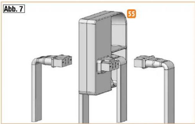
natural_image
3D CAD model of a mechanical assembly with two pipe extensions and a central housing (no text or symbols visible)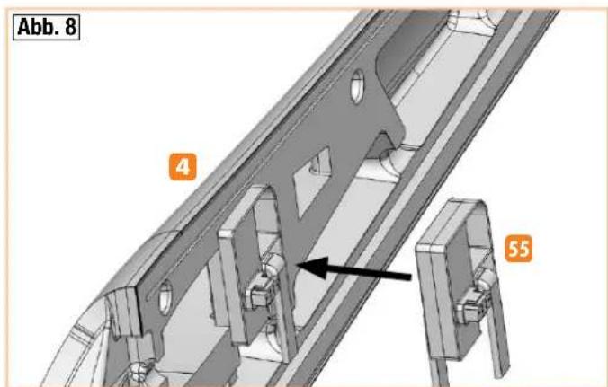
text_image
Abb. 8 4 55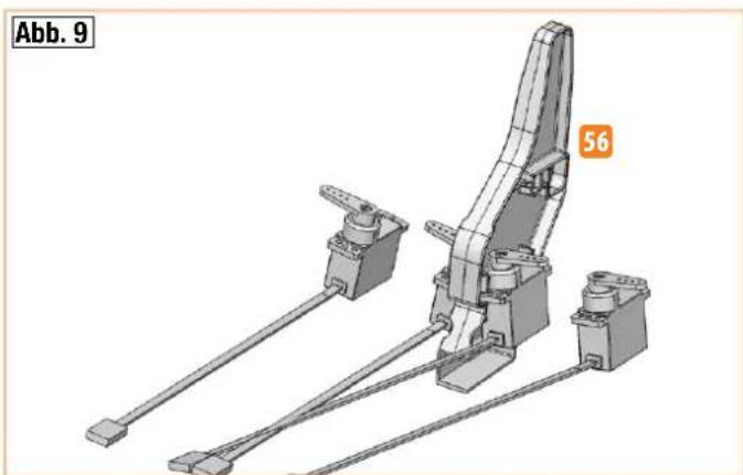
natural_image
Mechanical assembly diagram showing a lever mechanism with two shafts and a curved guide (no text or symbols)Abbildungen · Illustrations · Ilustrazioni · Ilustraciones
text_image
Abb. 10 4 56 (vgl. Abb. 9)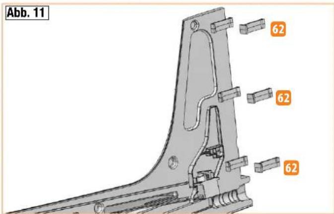
text_image
Abb. 11 62 62 62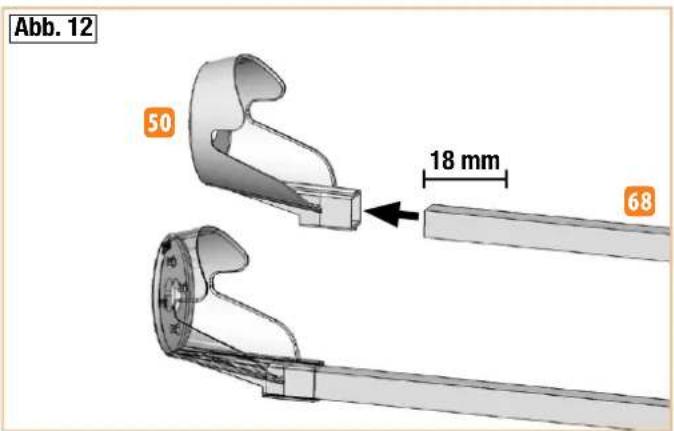
text_image
Abb. 12 50 18 mm 68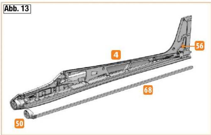
text_image
Abb. 13 4 56 68 50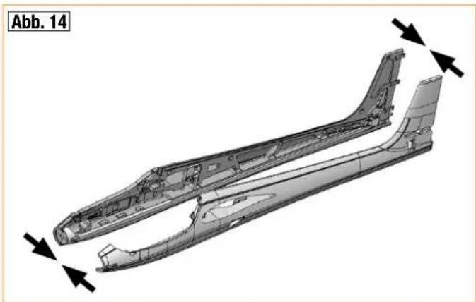
natural_image
Technical illustration of an aircraft fuselage with directional arrows indicating movement or force (no text or symbols present)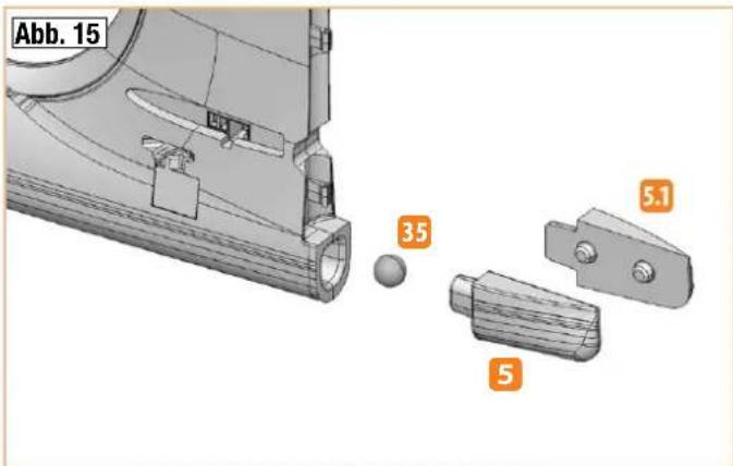
text_image
Abb. 15 35 5.1 5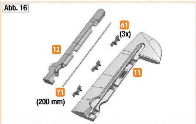
text_image
Abb. 16 12 61 (3x) 71 (200 mm) 11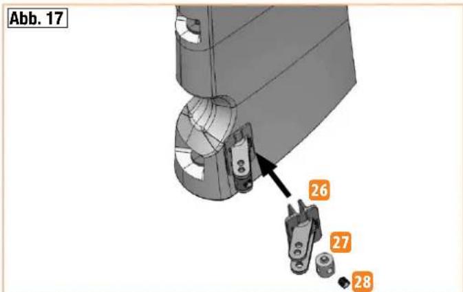
text_image
Abb. 17 26 27 28Abbildungen · Illustrations · Ilustrazioni · Ilustraciones
natural_image
Technical diagram of a mechanical component with internal features and directional arrows, labeled Abb. 18 (no text or symbols on the diagram itself)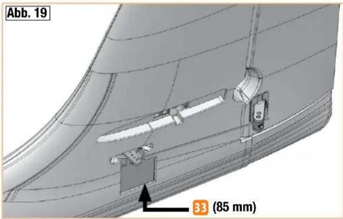
text_image
Abb. 19 33 (85 mm)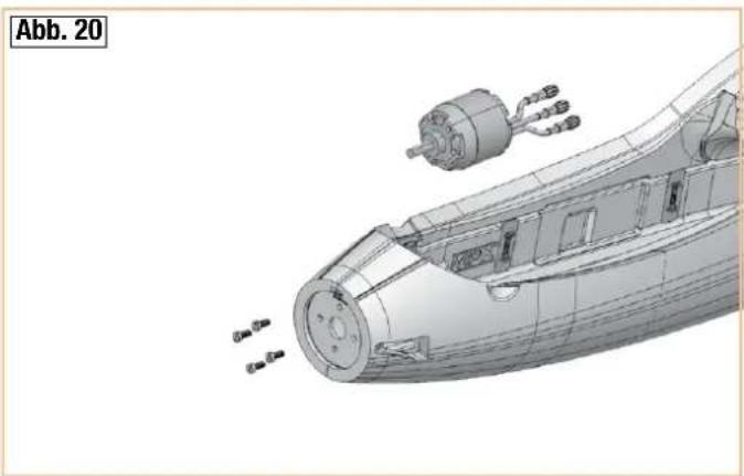
natural_image
3D technical illustration of a submarine internal structure with visible engine components and exhaust plume (no text or symbols)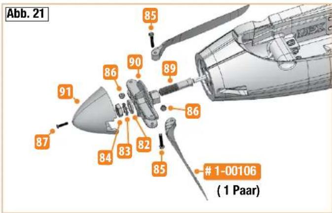
text_image
Abb. 21 85 90 89 86 86 87 91 84 83 82 851-00106
( 1 Paar)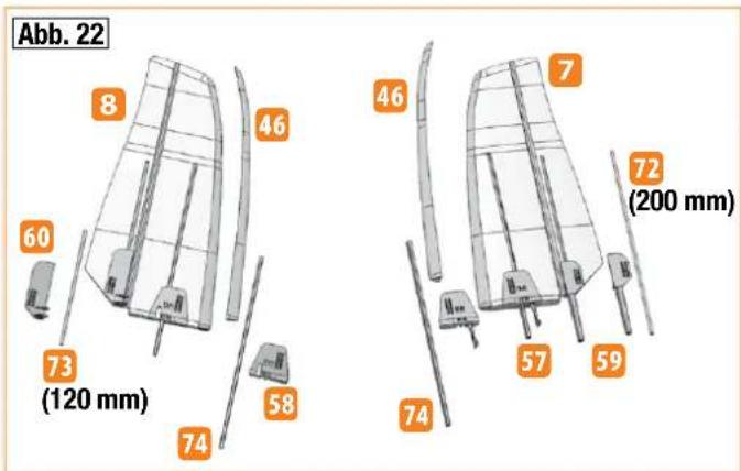
text_image
Abb. 22 8 46 60 73 (120 mm) 58 74 46 7 72 (200 mm) 57 59 74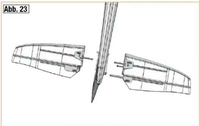
natural_image
Technical line drawing of a mechanical assembly with two views and a tool, labeled Abb. 23 (no text or symbols on the diagram itself)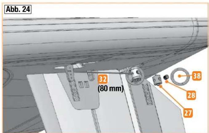
text_image
Abb. 24 32 (80 mm) 38 28 27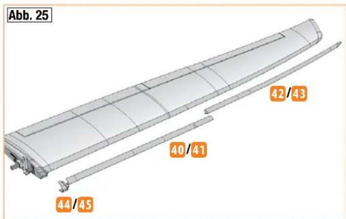
text_image
Abb. 25 40/41 42/43 44/45Abbildungen · Illustrations · Ilustrazioni · Ilustraciones
text_image
Abb. 26 51 / 52 36 (2x) 53 (2x) 34 (2x)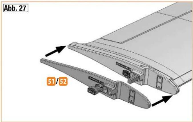
text_image
Abb. 27 51/52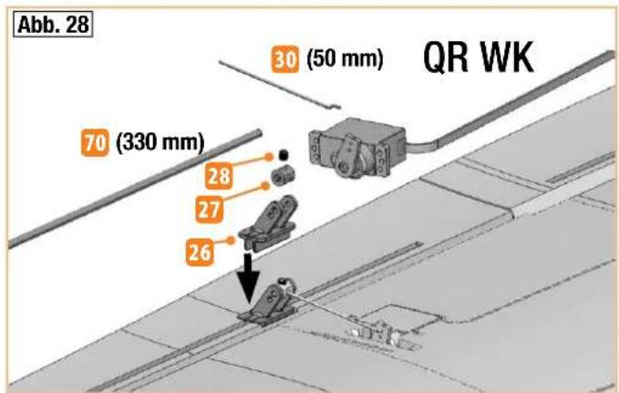
text_image
Abb. 28 30 (50 mm) QR WK 70 (330 mm) 28 27 26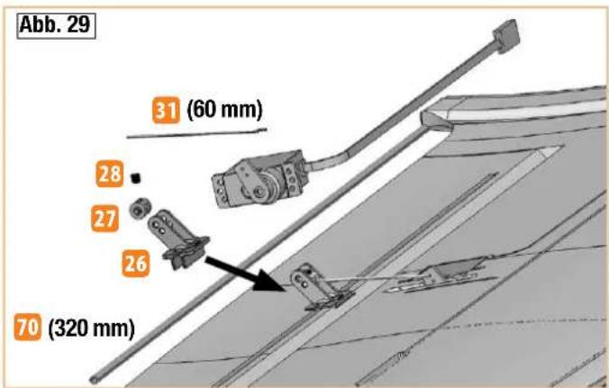
text_image
Abb. 29 31 (60 mm) 28 27 26 70 (320 mm)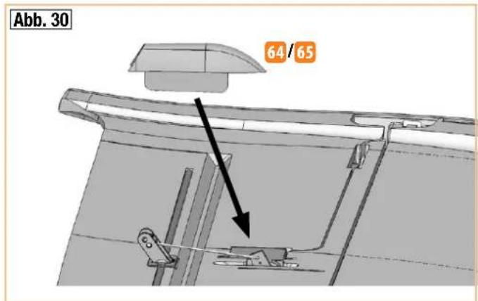
text_image
Abb. 30 64/65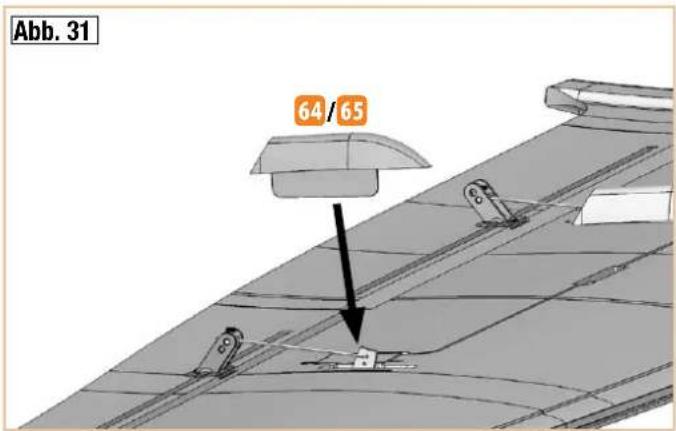
text_image
Abb. 31 64 / 65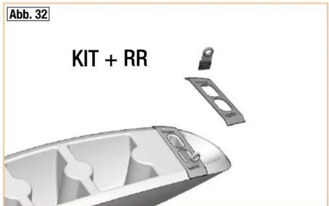
text_image
Abb. 32 KIT + RR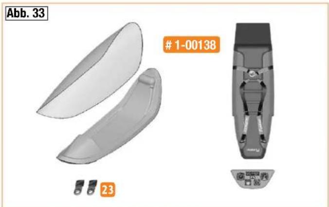
natural_image
3D model of a white ergonomic seat with two gray components, labeled Abb. 33 and #1-00138, shown without any text or symbols on the main body.Abbildungen · Illustrations · Ilustrazioni · Ilustraciones
text_image
Abb. 34 54 37natural_image
Exterior view of a modern industrial machine with black and green panels, MPX logo visible (no readable text or symbols beyond branding)
natural_image
Close-up of a white car's side panel with a black triangular cutout and a green rectangular highlight (no text or symbols visible)
natural_image
Abstract geometric design with green and white color blocks, no text or symbols presentnatural_image
Close-up of a white plastic tray with green and black stripes, featuring a red object inside (no visible text or symbols)
natural_image
Close-up of two white panels with green border and patterned background (no text or symbols)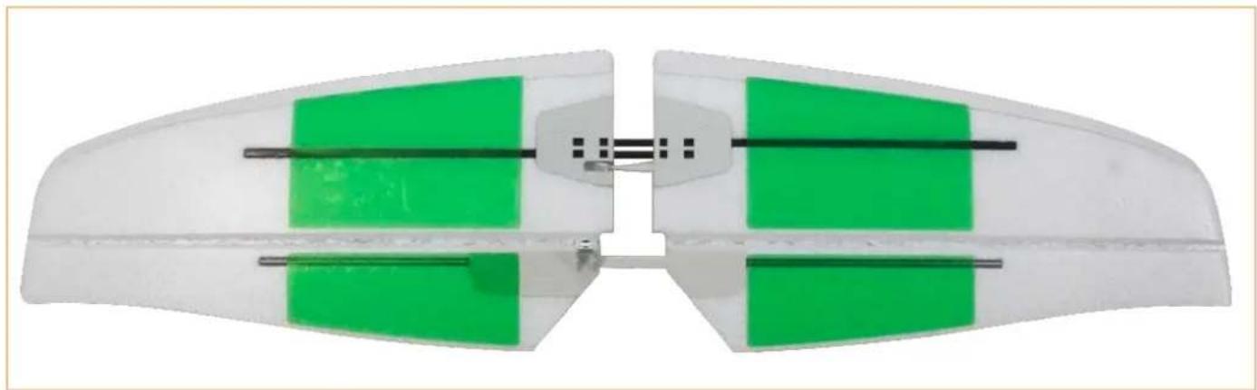
natural_image
Close-up of a white plastic aircraft fuselage with green rectangular panels and black horizontal lines (no text or symbols)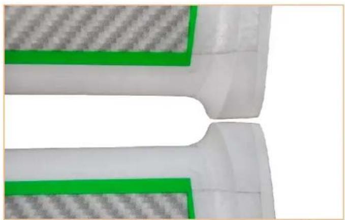
natural_image
Close-up of a white plastic component with green and gray hatched patterns, no visible text or symbols