FunnyCub - Remote control toy MULTIPLEX - Free user manual and instructions
Find the device manual for free FunnyCub MULTIPLEX in PDF.

| Product Type | Radio-controlled model airplane (assembly kit) |
| Brand | MULTIPLEX |
| Model | FunnyCub |
| Category | Radio-controlled toy (flying model) |
| Wingspan | 930 mm |
| Overall Length | 810 mm |
| Flying Weight | 180 g |
| Number of Channels | 4 (5 with optional flaps) |
| RC Functions | Elevator, rudder, ailerons, motor (optional flaps) |
| Flight Time | 6 minutes |
| Main Material | EPP (ELAPOR®) |
| Construction Type | Assembly kit requiring glue and tools |
| Power Supply | 2S 450 mAh LiPo battery (recommended: ROXXY EVO LiPo 2-450B) |
| Recommended Motor | ROXXY C27-13-1800 kV (V2 Extra 330 SC Indoor/FunnyCub Power System) |
| Recommended Servos | Hitec HS-40 (x4) |
| Recommended Receiver | RX-5 light M-LINK 2.4 GHz |
| Minimum Recommended Age | 14 years (adult supervision for minors) |
| Safety | Strict instructions: do not use near people, protect eyes, avoid moisture |
| Maintenance and Cleaning | Clean with a soft dry cloth; protect from moisture and dust |
| Spare Parts | Available from MULTIPLEX; use only recommended accessories |
Frequently Asked Questions - FunnyCub MULTIPLEX
User questions about FunnyCub MULTIPLEX
0 question about this device. Answer the ones you know or ask your own.
Ask a new question about this device
Download the instructions for your Remote control toy in PDF format for free! Find your manual FunnyCub - MULTIPLEX and take your electronic device back in hand. On this page are published all the documents necessary for the use of your device. FunnyCub by MULTIPLEX.
USER MANUAL FunnyCub MULTIPLEX
natural_image
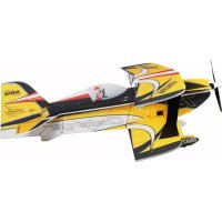
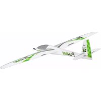
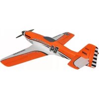
Model of a green and white FUMM CUB aircraft with visible propeller and wheels (no text or symbols on the aircraft body)FUNNYCUB
Next Generation

Accessories and tools, contents 10 - 11
Assembly instructions 12-13
Illustrations 20 - 22

Safety information for MULTIPLEX airplane models
When operating the model, all warning and safety information in the operating instructions must be observed.
The model is NOT A TOY in the conventional sense. If you use your model carefully, it will provide you and your spectators with lots of fun without posing any danger. If you do not operate your model responsibly, this may lead to significant property damage and severe injury. You and you alone are responsible for following the operating instructions and for ensuring the safety guidelines are adhered to.
When setting up the model, operators declare they are familiar with and understand the contents of the operating instructions, particularly regarding safety information, maintenance work, operating restrictions, and deficiencies.
This model may not be operated by children under the age of 14. If minors operate the model under the supervision of a responsible and competent adult pursuant to the law, this person is responsible for adhering to the information in the operating instructions.
THE MODEL AND THE ASSOCIATED ACCESSORIES MUST BE KEPT OUT OF REACH OF CHILDREN UNDER 3 YEARS OF AGE! CHILDREN UNDER 3 COULD SWALLOW REMOVABLE SMALL PARTS OF THE MODEL. RISK OF SUFFOCATION!
Multiplex Modellsport GmbH & Co. KG is not liable for loss, damage and consequential damage of any kind caused by incorrect operation, improper use or misuse of this product, including the accessories used along with it.
Proper use
The model may only be used in the hobby sector. No other type of use is permitted. To operate the model, only the accessories recommended by Multiplex may be used. The recommended components have been tested and adjusted for safe functioning together with the model. If other components are used or the model is modified, all claims against the manufacturer or retailer are void.
In order to minimize the risk when operating the model, observe the following points in particular:
- The model is controlled via a remote control. No remote control is safe from radio interference. Interference may lead to a loss of control of the model. Therefore, always ensure large safety distances in all directions when operating the model. As soon as even the smallest indication of radio interference presents itself, operation of the model must be halted immediately!
- The model may only be put into operation after a complete function and range test has been successfully carried out as per the instructions for the remote control.
- The model may only be flown in good visibility. Do not fly in poor light or in the direction of the sun in order to avoid glare.
-
The model may not be operated under the influence of alcohol or other intoxicants. The same applies for medicines that impair perception and responsiveness.
-
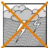
Only fly the model in wind and weather conditions in which you can safely control it. Even with light wind, take into account that turbulence may build up on objects and have an effect on the model.
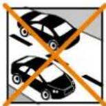
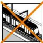
- Never fly in places where this would pose a danger to others, i.e. in residential areas, near power lines, roads, and railroad tracks.
- Never direct the model at people or animals! Avoid unnecessary risks and alert other pilots to potential hazards. Always fly in a manner that ensures neither you nor others are exposed to danger – even many years of accident-free flying experience are no guarantee for the next minute of flying time.

Residual risks
Even if the model is operated in accordance with the regulations and observing all safety aspects, there is always a residual risk.
Third-party liability insurance (powered model airplane) is therefore mandatory. If you are a member of a group or association, you might be able to take out the appropriate insurance there.
Ensure models and the remote control are properly maintained and are in good condition at all times.
Due to the construction and design of the model, the following dangers may arise in particular:
Injuries caused by the propeller: As soon as the battery is connected, the area around the propeller must be kept clear. Be aware that objects in front of the propeller may be sucked in and objects behind the propeller may be blown away. Always align the model ensuring it cannot move in the direction of other people if the motor starts up unintentionally. When performing adjustments for which the motor is running or may start up, the model must always be securely held in place by a helper.
- Crashes caused by control errors: Even the most experienced pilots can make mistakes. For this reason, only fly in a safe environment and at authorized model airplane flying fields.
- Crashes caused by technical failures, undetected damage from transportation or pre-existing damage: The model must be carefully inspected before each flight. Bear in mind that technical or material failures may occur at any time. Therefore, only operate the model in a safe environment.
- Adhere to operating limits: Excessively harsh flying weakens the structure of the model and may lead to technical and material failures as well as crashes immediately or, due to 'insidious' consequential damage, in later flights.
- Risk of fire due to malfunction of the electronics: Batteries must be stored safely. The safety information of the electronic components in the model, the battery, and the charging device must be observed.
Safety information for MULTIPLEX airplane models
The electronics must be protected from water. The controller and the batteries must be sufficiently cooled.
The instructions of our products may not be reproduced and/or published – not even in part – in print or electronic media without the express (written) permission of Multiplex Modellsport GmbH & Co. KG.
Safety information for MULTIPLEX construction kits
Familiarize yourself with the construction kit!
MULTIPLEX model kits are subjected to constant material inspection during production. We hope that you are satisfied with the contents of the kit. We nevertheless ask that you check all parts (according to the parts list) before use, as used parts cannot be exchanged. If a part is not OK, we will be happy to fix or replace it after verifying this. Please send the part with sufficient postage to our Service department. Be sure to include a short description of the fault along with the purchase receipt. We are continuously working on further developing the technology of our models. We reserve the right to make changes to the contents of the kit in terms of shape, dimension, technology, material, and equipment at any time and without warning. Please understand that no claims can be derived from specifications and illustrations in these instructions.
Caution!
Remote-controlled models, particularly airplane models, are not toys in the conventional sense. Their construction and operation requires technical understanding, a minimum level of artisan skills, discipline, and safety-awareness. Errors and negligences during building and operation may result in personal injury or property damage. As the manufacturer has no influence on proper assembly, maintenance, and operation, we explicitly refer to these dangers.
Warning:
Like any airplane, the model has static limitations! Nosedives and reckless maneuvers may result in damage to the model. Please note: In such cases, there is no replacement. Approach the limitations with caution. The model is fitted with the propeller recommended by us but can only withstand the loads if it is built flawlessly and is undamaged.
Crooked – does not really exist. If individual parts are bent during transit, they can be straightened again. Here, ELAPOR ^® behaves like metal. If you overbend the material slightly, it springs back minimally and retains its shape. The material of course has its limits – so don't overdo it!
Crooked – does indeed exist! If you want to paint your model, you do not need any primer for pretreatment when using the EC colors. Matt paints result in the best look. Under no circumstances may the paint coats be too thick or applied unevenly, otherwise the model will go out of shape and will be crooked, heavy or even unusable!
This model is not made of Styrofoam™! Therefore, adhesions using white glue, polyurethane or epoxy are not possible. These glues only stick superficially and may peel off in severe cases. Only use cyanoacrylate/ superglue of medium viscosity, preferably Zacki-ELAPOR® # 85 2727, the superglue optimized and adapted for ELAPOR® particle foam. When using Zacki-ELAPOR®, you can largely do without kickers or activators. If, however, you use other adhesives, and are unable to do without kickers/ activators, only spray outdoors for health reasons. Take care when working with all cyanoacrylate adhesives. These adhesives sometimes harden in seconds, so do not bring your fingers or other body parts into contact with them. To protect your eyes, be sure to wear protective goggles! Keep away from children! In some places, hot glue may also be used. If applicable, this is indicated in the instructions!
Working with Zacki-ELAPOR®
Zacki-ELAPOR ^® was developed specially for adhesion on our foam models made of ELAPOR ^® . In order to design the adhesion as optimally as possible, the following points should be taken into consideration:
- Avoid the use of activators. This causes the bonding to be significantly weakened. Especially for large-scale adhesion, we recommend allowing 24 hours for the parts to dry.
- Activators must only be used for point fixing. Only spray a little activator on one side. Allow the activator to flash off for approx. 30 seconds.
- For optimal bonding, sand down the surface using sandpaper (grain size 320).

text_image
ZACKI ELAPOR Chemistry: CEMBRANCE TRAVFOR: TRAVFOR SCREW
text_image
ZACKI85 2727
Accessories and tools
Essential accessories
• 1x Extra 330 SC Indoor / FunnyCub power set V2 # 1-01026
• 4x HS-40 servo # 11 2040
• 1x RX-5 light M-LINK 2.4 GHz receiver # 5 5808
• 1x ROXXY EVO LiPo 2 - 450B 30C with BID chip # 1-00016
EN
KIT contents
- Colour-printed EPP components for fuselage, wings, tailplane, fin and undercarriage
• CFRP spars for wings and fuselage
• CFRP undercarriage unit - Wheels
- All plastic parts, small items and linkage components required to complete the model
Essential tools and materials
• 1 x Zacki-ELAPOR® # 85 2727 # 85 2727
• 1 x Zacki-ELAPOR® super liquid # 85 2728 # 85 2728
• 1 x Zacki Activator #1-01032 #1-01032
- UHU ^ POR
- Small cross-point screwdriver
- Balsa knife
- Pointed-nose pliers
• 1 sheet abrasive paper, 320-grit
- 1 mm drill
- 1.5 mm drill
Specification
| Wingspan 930 mm | |
| Overall length 810 mm | |
| All-up weight 180 g | |
| Control channels 4 (5) | |
| RC functions Elevator, rudder, aileron, throttle(optional landing flaps) | |
| Flight time 6 min. | |
Parts List
| Part No. | Quant. | Description | Material Dimensions | |
| 1 | 1 | FunnyCub building instructions | Paper | DIN A4 |
| 2 | 1 | Model complaint notification | Paper | DIN A5 |
| 3 | 1 | Upper fuselage section | EPP | Ready made |
| 4 | 1 | Lower fuselage section | EPP | Ready made |
| 5 | 1 | Fuselage centre section | EPP | Ready made |
| 6 | 1 | Left wing | EPP | Ready made |
| 7 | 1 | Right wing | EPP | Ready made |
| 8 | 1 | Left tailplane | EPP | Ready made |
| 9 | 1 | Right tailplane | EPP | Ready made |
| 10 | 1 | Fin | EPP | Ready made |
| 11 | 4 | Outer wheel section | EPP | Ready made |
| 12 | 2 | Inner wheel section | EPP | Ready made |
| 13 | 10 | Round-section rod | CFRP | 1.0 ∅ x 400 mm |
| 14 | 3 | Round-section rod | CFRP | 0.8 ∅ x 500 mm |
| 15 | 2 | Round-section rod | CFRP | 1.5 ∅ x 228 mm |
| 16 | 2 | Round-section rod | CFRP | 1.5 ∅ x 215 mm |
| 17 | 2 | Round-section rod | CFRP | 1.0 ∅ x 140 mm |
| 18 | 4 | Round-section rod | CFRP | 1.0 ∅ x 100 mm |
| 19 | 4 | Round-section rod | CFRP | 1.0 ∅ x 250 mm |
| 20 | 2 | Round-section rod (for linkages) | CFRP | 1.5 ∅ x 60 mm |
Accessories and tools
| Part No. | Quant. Description Material Dimensions | ||
| 21 2 Round-section rod (wheel axles) CFRP 2.0 ∅ x 30 mm | |||
| 22 2 Rectangular -section strip CFRP 3 x 0.5 x 800 mm | |||
| 23 2 Rectangular-section strip CFRP 3 x 0.5 x 90 mm | |||
| 24 1 Rectangular-section strip CFRP 3 x 0.5 x 190 mm | |||
| 25 2 Rectangular-section strip CFRP 3 x 0.5 x 125 mm | |||
| 26 1 Rectangular-section strip CFRP 3 x 0.5 x 100 mm | |||
| 27 1 Firewall Plastic Ready made | |||
| 28 1 L.H. aileron horn Plastic Ready made | |||
| 29 1 R.H. aileron horn Plastic Ready made | |||
| 30 1 Rudder horn Plastic Ready made | |||
| 31 1 Elevator horn Plastic Ready made | |||
| 32 1 L.H. axle bracket Plastic Ready made | |||
| 33 1 R.H. axle bracket | Plastic Ready made | ||
| 34 12 Pushrod guide | Plastic Ready made | ||
| 35 4 Undercarriage mounting plate | Plastic Ready made | ||
| 36 4 Wheel hub | Wood | 30 mm ∅ | |
| 37 2 Wheel spacer ring | Wood | 7 mm ∅ | |
| 38 2 Adapter tube Plastic 2 ∅ x 5 mm | |||
| 39 4 Clevis | Plastic Ready made | ||
| 40 4 Clevis pin | Brass | 1 ∅ x 5 mm | |
| 41 4 Ball-link | Plastic / brass | Ready made | |
| 42 4 Ball-link ball | Brass | M1.5 x 4 mm | |
| 43 2 Threaded coupler | Brass | M2 x 20 mm | |
| 44 2 Threaded coupler | Brass | M2 x 14 mm | |

Building instructions
Important: before you start building
Please ensure that all the model components are present in the kit by checking them off in the Parts List on page 10 and 11.
It is important to build the model on a clean and perfectly flat surface to ensure that the structure is free of warps, and that the components are not damaged during assembly. Be sure to cover the building board with clear plastic film to avoid the components sticking to the surface.
Joints between EPP components are best made using UHU ^® POR. This is the procedure: apply a thin film of adhesive to both surfaces to be glued, then allow it to air-dry for about eight minutes before pressing the parts together. The strength of the joint is determined by the pressure you exert, rather than the length of time you exert it.
When CFRP rods and strips have to be inserted into EPP parts, press the strip into the appropriate slot, then run low-viscosity (thin) Zacki-ELAPOR® super liquid along it. A little activator spray will harden the adhesive immediately.
All other glued joints can be made using standard Zacki-ELAPOR®.
Although the carbon rods and strips are supplied cut to length, you may need to trim them slightly. If the correct length is not stated, we recommend that you hold the strip in position, and cut it to length using pliers or side-cutters. The kit includes an ample supply of carbon strip.
1. Preparing the individual components
The control surface hinges need to be rendered more flexible to ensure that they move freely when the model is flying. This is accomplished by folding the control surfaces through 180° before construction; leave them in this position for about an hour. Fig. 1
Cover a clean, flat surface with clear plastic film, and lay the fin 10 on it, left-hand side facing up as shown. Glue the rectangular-section CFRP strip 26 in the slot in the rudder. The rudder horn 30 can now be glued in the slot. Fig. 2
Glue the two tailplane halves 8, 9 and the elevator to the fuselage centre section 5. The correct orientation is determined by the decals, as shown in the picture. Now glue two rectangular-section CFRP strips 25 and two CFRP rods 14 in place. Fig. 3
Turn the fuselage centre section over, and glue the rectangular-section CFRP strip 24 to the top surface. Fig. 4
The two wing panels 6, 7 can now be glued together. Install two rectangular-section strips 22, four CFRP rods 13 and two rectangular-section strips 23 in place. Note that the four CFRP rods 13 cross over as shown. The two horns 28, 29 can now be glued in the appropriate slots. Fig. 5
Glue the CFRP rod 14 in the lower fuselage side section 4, allowing it to project at the tail end by 1.5cm . The four undercarriage mounting plates 35 can now be glued securely to both sides of the fuselage. Fig. 6
Glue the wheel components together as follows: glue the hubs 36 to both sides of each inner wheel section 12, then glue the outer wheel components 11 to both sides of the centre parts. Fig. 7
If you wish, you can sand the edges of the wheels to a rounded section.
2. Fitting the lower fuselage section
Glue the lower fuselage section 4 to the fuselage centre section 5, ensuring that the parts are straight, and at right-angles to each other.
Glue the front 16 and rear 15 undercarriage legs to the fuselage.
Glue the CFRP rods 17 in place at the nose to stiffen this area. Cut the CFRP rods 13 to the correct length, and install them as shown in order to stiffen the remainder of the fuselage. Fig. 8
The best method is to hold the rod in place on the model, and cut it to the required length using pliers or side-cutters.
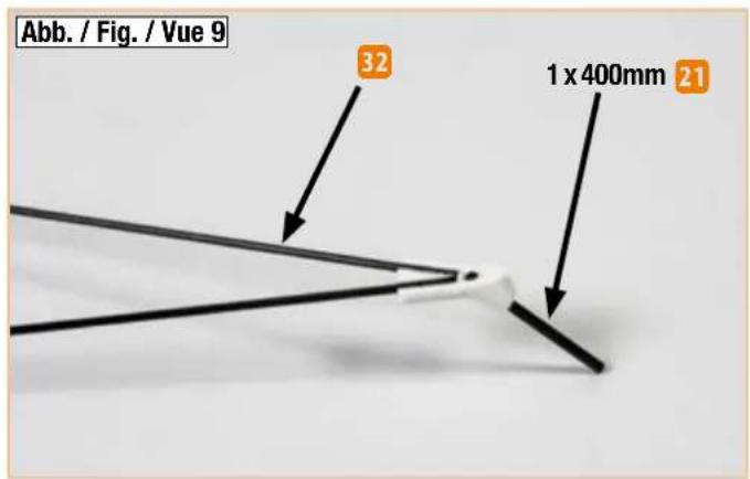
Glue the undercarriage legs and the CFRP wheel axles 21 to the axle brackets 32, 33. Remember to make one left-hand and one right-hand assembly. Fig. 9
Now fit each wheel on its axle followed by a spacer ring, and glue the spacer rings in place. Fig. 10
Check that the wheels are free to rotate.
3. Installing the servos and the elevator horn
Glue the two aileron servos (2 x Hitec HS-40, # 112040) in the openings in the wing using a few drops of Zacki; they should finish flush with the top surface of the wing. Fig. 11
The next step is to glue the elevator and rudder servos (2 x Hitec HS-40, # 112040) in the appropriate openings in the fuselage using a few drops of Zacki. Glue the elevator horn 31 in the tailplane. Fig. 12
4. Fitting the upper fuselage section
The upper fuselage section 3 can now be glued to the fuselage centre section, taking care to keep the parts straight and at right-angles to each other. Glue the fin 10 in place. Install four CFRP rods 18 and two additional CFRP rods 13 as shown. Complete this stage by gluing the firewall 27 to the fuselage nose using Zacki. Fig. 13
5. Installing the aileron linkages
Use a servo tester or your radio control system to set the aileron servos to centre (neutral), then fit the large double-ended output levers (supplied in the kit) on the servos before snipping off the unwanted end. Locate the hole in the output arm where the pushrod will be fitted, and open up the hole using a 1.5 mm ∅ drill; we suggest you use the central hole. The aileron pushrods are assembled as shown in the illustration: glue an M2 x 20 mm threaded coupler 43 to one end of the CFRP rod 20, and screw a ball-link 41 on the coupler, holding the coupler in pliers to prevent it turning. Attach the linkage ball to the servo output arm using the screw 42, then thread the pushrod into the ball-link. Determine the length to the aileron horn, and cut the pushrod to the correct length before gluing the ball-link to the pushrod. You can now fine-tune the pushrod length using the threaded coupler; both ailerons should be exactly horizontal when the servos are at neutral. When you are satisfied, screw the pushrods to the aileron horns. Fig. 14
Building instructions
6. Installing the elevator and rudder linkages
Use a servo tester or your radio control system to set the elevator and rudder servos to centre (neutral), then fit the large double-ended output levers (supplied in the kit) on the servos before snipping off the unwanted end. Drill out the hole in the output arm to 1 mm ∅. For the elevator we suggest using the second hole from the inside, and for the rudder the innermost hole. Glue six pushrod guides 34 in the holes on each side of the fuselage. Fig. 15
The two pushrods are assembled as shown in the illustration: glue an M2 x 14 mm threaded coupler 44 to one end of the CFRP rod 13, and screw a ball-link 39 on the coupler, holding the coupler in pliers to prevent it turning. Fig. 16
Thread each pushrod through the pushrod guides from the front, and attach the clevis to the servo output arm by pressing a clevis pin 40 through with a pair of pliers.
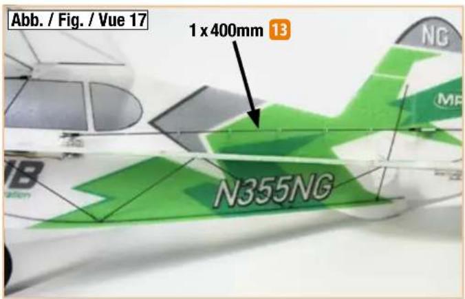
Complete the linkages as described for the ailerons, but please note that an adapter tube 38 has to be fitted in the clevis on the other end of the pushrod in order to obtain a close fit between the clevis and the CFRP pushrod. Ensure that all the glued joints involving the control linkages are sound. Fig. 17
7. Gluing the wing in place
The prepared wing can now be glued to the fuselage. Set the wing straight and 'square', and glue two struts on each side as shown. These consist of the CFRP rods 19, which have to be cut to the correct length. Fig. 18
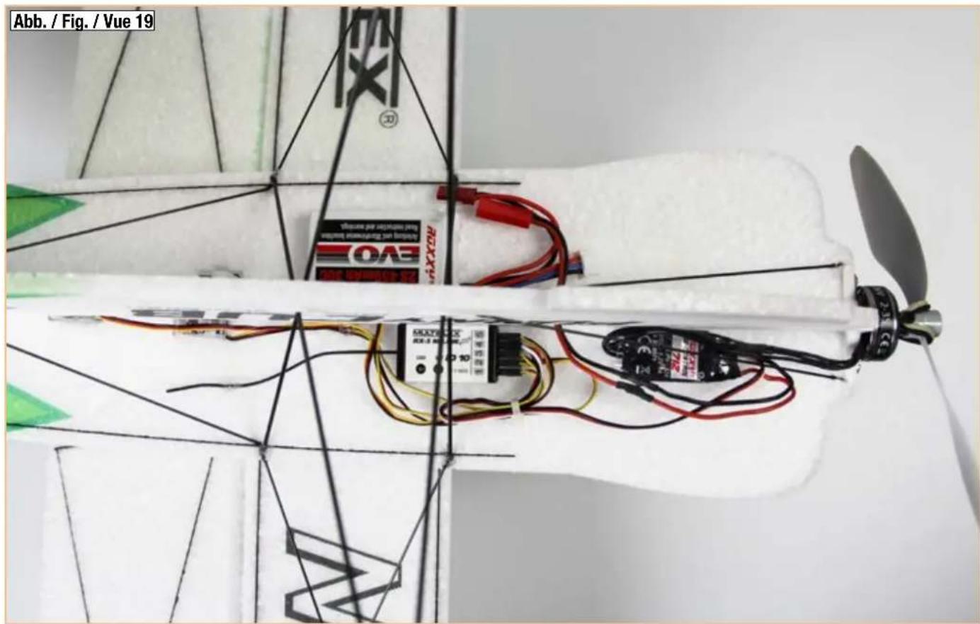
8. Installing the RC components
Fix the motor (ROXXY C27-13-1800kV # 1-00018) to the front face of the firewall; the screws are included in the hardware pack supplied with the motor. Attach the speed controller (ROXXY BL Control 715 BEC # 1-01050) to the lower fuselage section using hook-and-loop tape. The receiver and flight battery can also be fixed to the fuselage using small pieces of hook-and-loop tape. When attaching the tape to the battery we recommend the application of a little UHU® POR to the surface, allowing it to air-dry for about ten minutes. Fig. 19
9. Centre of Gravity, control surface travels
The model's Centre of Gravity should be located at the 55 mm point, measured from the wing leading edge close to the fuselage. The control surface travels are set to the pilot's individual preference, but we recommend about 80% EXPO on elevator, 60% EXPO on aileron and rudder. Since the ailerons are operated by separate servos, they can also be lowered together to act as landing flaps. A programming template for the Cockpit SX radio control system can be found on our Internet site.
natural_image
Five black circular mechanical components with radial cutouts, arranged on a plain white background (no text or symbols visible)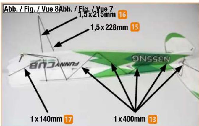
text_image
Abb. / Fig. / Vue 8Abb. / Fig. / Vue 7 1,5 x 215mm 16 1,5 x 228mm 15 1 x 140mm 17 1 x 400mm 13 SNSSENAbbildungen · Illustrations · Ilustrazioni · Ilustraciones
text_image
Abb. / Fig. / Vue 9 32 1 x 400mm 21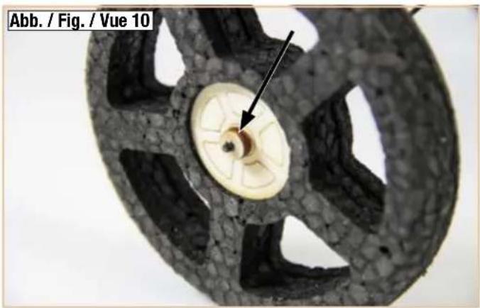
natural_image
Close-up of a mechanical component with a central hole and textured outer ring, labeled Abb. / Fig. / Vue 10 (no other text or symbols)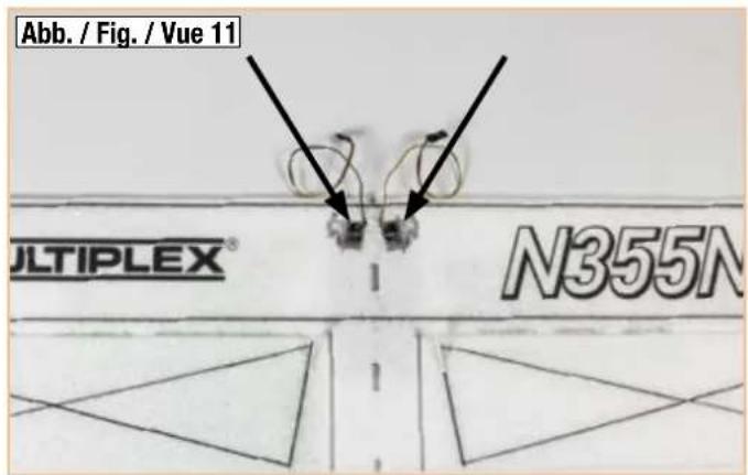
text_image
Abb. / Fig. / Vue 11 JLTIPLEX® N355N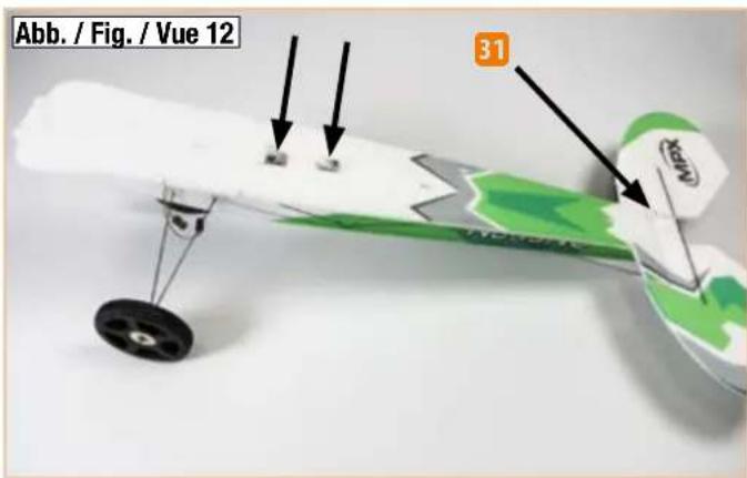
text_image
Abb. / Fig. / Vue 12 31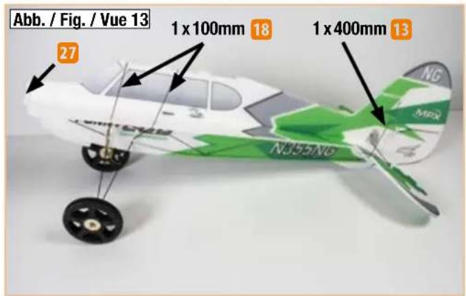
text_image
Abb. / Fig. / Vue 13 27 1 x 100mm 18 1 x 400mm 13 NG MPX N355/N6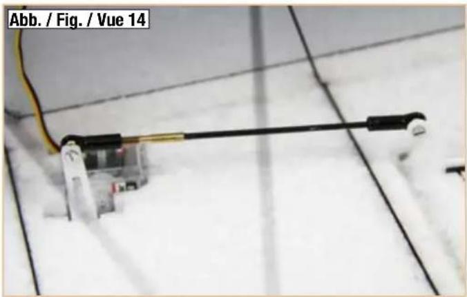
natural_image
Close-up of a mechanical or electrical component with wires and connectors, no visible text or symbols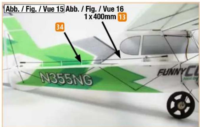
text_image
Abb. / Fig. / Vue 15 Abb. / Fig. / Vue 16 1 x 400mm 13 34 N355NG FUNNYCL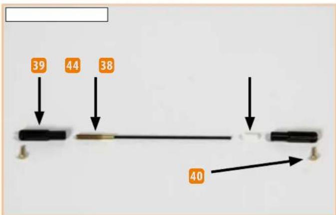
text_image
39 44 38 40Abbildungen · Illustrations · Ilustrazioni · Ilustraciones
text_image
Abb. / Fig. / Vue 17 1 x 400mm 13 N355NG NB MF NG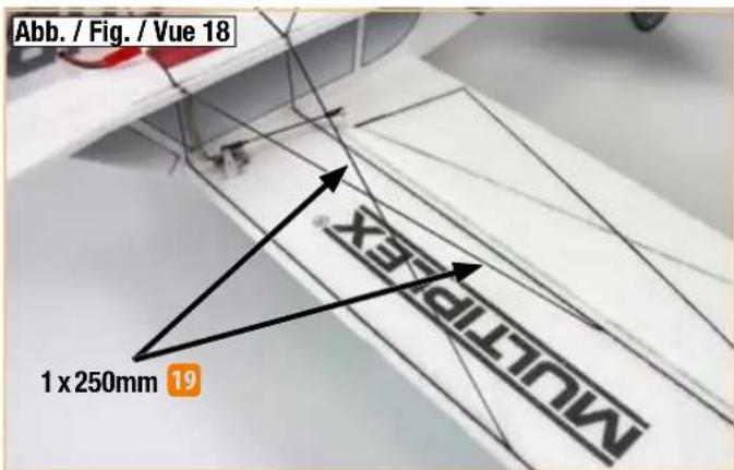
text_image
Abb. / Fig. / Vue 18 1 x 250mm 19 MULTIFLEX®