BLControl 900 Serie - Remote control toy MULTIPLEX - Free user manual and instructions
Find the device manual for free BLControl 900 Serie MULTIPLEX in PDF.

| Product type | Brushless speed controller for RC models (airplane, helicopter, boat, car) |
| Brand | Multiplex |
| Models | BL 908, BL 918, BL 930, BL 930-6, BL 940-6, BL 950-6, BL 960-6, BL 9100-6 |
| Continuous current (max) | 8 A (BL 908) to 100 A (BL 9100-6) |
| Peak current (max) | 12 A (BL 908) to 110 A (BL 9100-6) |
| Power supply | 6 to 18 NiMH/NiCd cells or 2 to 6 LiPo cells depending on model |
| BEC output voltage | 5.5 V, max current 2 A to 3 A (depending on model) |
| Weight | 15 g (BL 908) to 67 g (BL 9100-6) |
| Dimensions (L x W x H) | 35 x 22 x 7 mm (BL 908) to 76 x 26 x 13 mm (BL 9100-6) |
| Operating temperature | Not specified in the manual, estimate: 0°C to 50°C |
| Switching frequency | 32 kHz |
| Protection functions | POR (power-on protection), PCO (under-voltage cutoff), TOP (thermal overload protection), Rx filter, Cool Power FET (anti-interference) |
| Programming | Without device (5 parameters via throttle stick) or with programming device (ref. 31 8633) |
| Operating modes | Airplane (Air), Helicopter (Heli), Boat (Boat), Car (Car) |
| Maintenance and cleaning | Avoid contact with grease, oil or water. Ensure sufficient air circulation. Insulate solder joints with heat shrink tubing. |
| Safety | Respect polarity, avoid short circuits, do not put hands in rotating parts, firmly secure motors. |
| Spare parts and repairability | Repairs only by an authorized Multiplex service center. Spare parts not listed in the manual. |
| General information | Legal warranty, CE declaration of conformity, disposal via waste center (WEEE). |
Frequently Asked Questions - BLControl 900 Serie MULTIPLEX
User questions about BLControl 900 Serie MULTIPLEX
0 question about this device. Answer the ones you know or ask your own.
Ask a new question about this device
Download the instructions for your Remote control toy in PDF format for free! Find your manual BLControl 900 Serie - MULTIPLEX and take your electronic device back in hand. On this page are published all the documents necessary for the use of your device. BLControl 900 Serie by MULTIPLEX.
USER MANUAL BLControl 900 Serie MULTIPLEX
CUT OFF TYPE SOFT OFF HELI
5. Advance Timing (Motor-Timing)
ADVANCE TIMING 8
1.1. Safety instructions 10
1.2.Guarantee and limitation of liability 10
1.3. CE Conformity declaration 10
1.4. Disposal Notes 11
2. Connections, special features 11
3. Specification 11
4. Programming the stick positions 12
10 5. Programming the speed controller parameters without using the Programmer 13
5.1. Characteristics, protective functions 14
5.2. Programming example 14
6. Settings with the programmer 15
6.1. Overview of programming facilities 15
7. Programming in detail 16

1. Introduction
A range of compact, lightweight speed controllers exploiting the new Cool Power FET technology, resulting in particularly high-performing, extremely versatile controllers which are ideal for model aircraft, boats, cars and electric helicopters. The speed controllers are particularly well suited for use in conjunction with the ROXXY series of brushless motors, but can also be employed with other BL motors. Please read right through these instructions before connecting and using the controller.
1.1. Safety instructions
- Take notice of the controller technical data.
- Maintain correct polarity of all connections.
- Avoid short-circuits at all costs.
- Install the controller so that it cannot come into contact with oil, grease and water.
1.2. Guarantee and limitation of liability
MULTIPLEX Modellsport GmbH & Co.KG does not assume any liability for loss, damage or costs which arise through the improper use and operation of our products, or which are connected with such operation in any way. As far as is legally permissible, the obligation of MULTIPLEX Modellsport GmbH & Co.KG to provide compensation for damages, on whatever legal basis, is limited to the invoice amount of the quantity of MULTIPLEX Modellsport GmbH & Co.KG goods that were directly affected by whatever incident gave rise to the damage. This does not apply if MULTIPLEX Modellsport GmbH & Co.KG is obliged to accept unlimited liability in accordance with mandatory law for deliberate or gross negligence.
Our products are covered by the currently valid statutory guarantee regulations. If you wish to make a claim under guarantee, please contact the model shop where you purchased the product. The guarantee does not cover malfunctions caused by the following:
- Ensure suffient air circulation for cooling.
- Avoid bodily contact with all rotating parts whilst operating.
- Securely mount the motor and restrain all cables.
We reserve the right to introduce technical modifications.
- Improper operation
- Maintenance that was performed incorrectly, late or not at all, or performed by a non-authorized body
- Incorrect connections
Use of non-original MULTIPLEX accessories - Modifi cations / repairs that were not carried out by MULTIPLEX or a MULTIPLEX Service Centre
- Accidental or deliberate damage
- Faults due to normal wear and tear
Operation outside the technical specifi cations or in connection with components from other manufacturers.
MULTIPLEX Modellsport GmbH & Co.KG
1.3. CE Conformity declaration
This device has been assessed and approved in accordance with European harmonised directives. This means that you possess a product whose design and construction fulfil the protective aims of the European Community designed to ensure the safe operation of equipment. If required, you can request MULTIPLEX Modellsport GmbH & Co.KG to supply a copy of the unit's Conformity Declaration. Please contact the company using the contact details at the foot of the page.
1.4. Disposal Notes
Electrical equipment marked with the cancelled waste bin symbol must not be discarded in the standard household waste; instead it should be taken to a suitable specialist disposal system.
In the countries of the EU (European Union) electrical equipment must not be discarded via the normal domestic refuse system (WEEE - Waste of Electrical and Electronic Equipment, Directive 2002/96/EG).
You can take unwanted equipment to your nearest local authority waste collection point or recycling centre. There the equipment will be disposed of correctly and at no cost to you.
By returning your unwanted equipment you can make an important contribution to the protection of the environment!
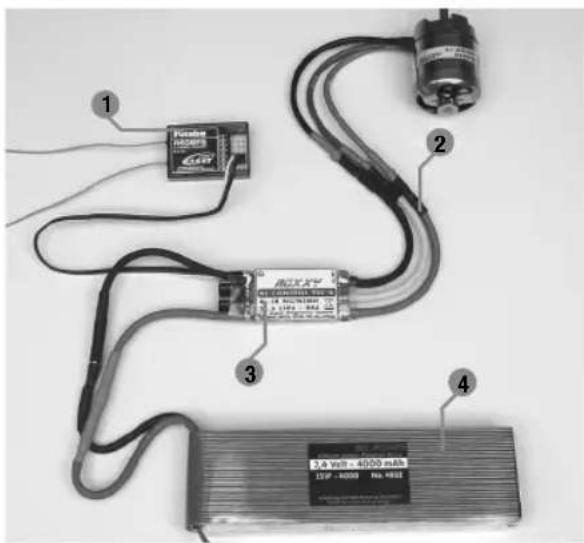
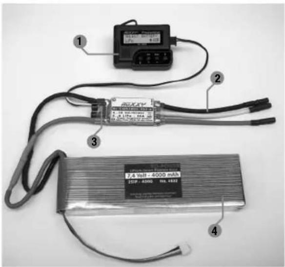
2. Connections, special features
Prepare the red (positive) wire and the black (negative) wire for connection to the drive battery by attaching a suitable connector system. Insulate each individual soldered joint with a heat-shrink sleeve.
1 Receiver
2 Motor connection
3 Motor controller
4 Drive battery

3. Specification
| BL 908 No. 31 8627 | BL 918 No. 31 8628 | BL 930 No. 31 8629 | BL 930-6 No. 31 8630 | |
| Load current 8 A 18 A 30 A | 30 A | |||
| Peak load 12 A 22 A 35 A 35 A | ||||
| Dimensions (mm) 35 x 22 x 7 38 x 22 x 7 49 x 25 x | 10 49 x 25 x 10 | |||
| Weight (g) 15 g 25 g 29 g 29 g | ||||
| Cell number 6...12 NC/NiMh | 2...4 LiPo | 6...12 NC/NiMh | 6...12 NC/NiMh | 6...18 NC/NiMh |
| 2...4 LiPo | 2...4 LiPo | 2...6 LiPo | ||
| BEC 5,5 Volt max. 2 A 5,5 Volt max. | 2 A 5,5 Volt max. | 2 A 5,5 Volt max.2 A | ||
| SPS | ✓ | ✓ | ✓ | ✓ |
| Rx-Filter | ✓ | ✓ | ✓ | ✓ |
| PCO | ✓ | ✓ | ✓ | ✓ |
| POR | ✓ | ✓ | ✓ | ✓ |
| hec | 32 kHz | 32 kHz | 32 kHz | 32 kHz |
| TP | ✓ | ✓ | ✓ | ✓ |
| Cool Power FET | X | X | ✓ | ✓ |
3. Specific cation

| BL 940-6 Nr. 31 8631 | BL 950-6 Nr. 31 8632 | BL 960-6 Nr. 31 8634 | BL 9100-6 Nr. 31 8635 | |
| Load current 40 A 50 A 60 A 100 A | ||||
| Peak load 50 A 60 A 70 A 110 A | ||||
| Dimensions (mm) 66 x 25 x 10 66 x 25 x 10 66 x 25 x 10 76 x 26 x 13 | ||||
| Weight (g) 47 g 49 g 49 g 67 g | ||||
| Cell number 6...18 NC/NiMh | 2...6 LiPo | 6...18 NC/NiMh | 6...18 NC/NiMh | 6...18 NC/NiMh |
| 2...6 LiPo | 2...6 LiPo | 2...6 LiPo | ||
| BEC 5,5 Volt | max. 3 A/kurz. 5 A | 5,5 Volt | 5,5 Volt | 5,5 Volt |
| max. 3 A/kurz 5 A | max. 3 A/kurz. 5 A | max. 3 A/kurz. 5 A | ||
| SPS | ✓ | ✓ | ✓ | ✓ |
| Rx-Filter | ✓ | ✓ | ✓ | ✓ |
| PCO | ✓ | ✓ | ✓ | ✓ |
| POR | ✓ | ✓ | ✓ | ✓ |
| hec 32 kHz 32 kHz 32 kHz 32 kHz | ||||
| TP | ✓ | ✓ | ✓ | ✓ |
| Cool Power FET | ✓ | ✓ | ✓ | ✓ |
4. Programming the stick positions
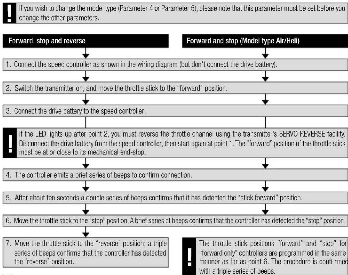
5. Programming the speed controller parameters without using the Programmer
There are five programmable parameters.
This is the procedure for entering programming mode:
- Connect the speed controller as shown in the wiring diagram (but don't connect the drive battery).
- Switch the transmitter on, and move the throttle stick to the "forward" position.
- Connect the drive battery to the speed controller.
- The controller emits a brief series of beeps to confirm connection.
- After about ten seconds you will hear a double series of beeps, followed by a triple series of beeps after a further three seconds.
The speed controller now emits a continuous series of single beeps and LED fl ashes to confirm that Parameter 1 has been selected.
The parameter to be programmed is selected using the following sequence of throttle stick positions: move the throttle stick briefly from the "forward" position to the "stop" position then back to the "forward" position again. The controller now emits continuous double beeps and LED fl ashes to confirm that Parameter 2 has been selected. Repeat the sequence of throttle stick movements described above in order to select Parameters 3, 4 and 5.
| Parameter type Beep LED | |||
| Parameter 1 Battery type 1 x 1 x | |||
| Parameter 2 Direction of motor rotation 2 x 2 x | |||
| Parameter 3 - Brake ON/OFF (AIR) | 3 x 3 x | ||
| - Brake ON/OFF (HELI) | |||
| Parameter 4 Model type AIR/HELI 4 x 4 x | |||
| Parameter 5 Model type BOAT/CAR | 5 x 5 x | ||
To change the parameter you must first move the throttle stick from the "forward" position to the "stop" position, and leave the throttle stick in the "stop" position for at least three seconds.
The actual parameter is altered by moving the throttle stick rapidly from the "stop" position to the "forward" position and back.
| Parameter type | LED ON Beep every 2 Sec. | LED flashes Beep every 0,5 Sec. |
| Battery type | LiPo | NiCD/NiMH |
| Direction of rotation | Normal | Reverse |
| Brake (AIR) | OFF | ON |
| Governor (HELI) | OFF | ON |
| Reverse (CAR, BOAT) | OFF | ON |
| Model type (AIR/HELI) | AIR | HELI |
| Model type (BOAT/CAR) | BOAT | CAR |
The change is stored by moving the throttle stick from the "stop" position to the "forward" position.
The final step is to disconnect the drive battery; this concludes the process and adopts the programmed settings. The speed controller is now programmed, and is ready for use.

5.1. Characteristics, protective functions
| BEC Integral receiver power supply. | |
| POR Power-on guard, prevents the motor starting accidentally. | |
| PCO | Low voltage cut-off. The speed controller switches the motor off in good time when the battery is nearly discharged, in order to reserve sufficient battery capacity for controlling the model, and in order to avoid deep-discharging the drive battery (optionally for NC/NiMH or LiPo battery). |
| hec | High pulse frequency for fine control of motor speed; also avoids premature magnet degradation. |
| SPS Super Programming System | |
| Cool Power FET New generation of transistors | |
| WP Splashproof construction (Water Protect) | |
| Hec High motor frequency | |
| Opto Galvanic separation between motor interference and receiver. | |
| RX-Filter Switches the speed controller off if the transmitter signal is absent or invalid. | |
| TOP Double overload protection (Thermal Overload Protection) | |
| TP Thermal fuse (Thermal Protection) | |
5.2. Programming example
The following example elucidates the method of setting up the speed controller to match individual stick positions, followed by the programming of the model type: AIR and brake ON.
Programming the stick positions
- Switch the transmitter on, and move the throttle stick to the "forward" position.
- Connect the drive battery to the speed controller (unit emits a brief beep).
- After about ten seconds a double series of beeps confirms that it has detected the "stick forward" position.
- Move the throttle stick to the "stop" position. A brief series of beeps confirms that the controller has detected the "stop" position.
- Disconnect the drive battery from the speed controller.
Programming the controller parameters
- Switch the transmitter on, and move the throttle stick to the "forward" position.
- Connect the drive battery to the speed controller (unit emits a brief beep).
- After about ten seconds you will hear a double series of beeps, followed by a triple series of beeps after a further three seconds.
- The controller is now in programming mode for Parameter 1 (continuous single beeps and LED flashes).
- Select Parameter 4 by moving the throttle stick four times from the "forward" position to the "stop" position and back to the "forward" position again (continuous quadruple beeps and LED flashes).
- To change the parameter you must first move the throttle stick from the "forward" position to the "stop" position, leaving the throttle stick at the "stop" position for at least three seconds.
- Select the "Air" mode (beep sounds/LED lights up every two seconds).
- The change is stored by moving the throttle stick from the "stop" position to the "forward" position.
Setting Air Brake On
- When you have stored the setting as described above, the speed controller returns to parameter select: Parameter 4.
- Select Parameter 3 by moving the throttle stick four times from the "forward" position to the "stop" position and back to the "forward" position again (continuous triple beeps and LED flashes).
- To change the parameter you must first move the throttle stick from the "forward" position to the "stop" position, leaving the throttle stick at the "stop" position for at least three seconds.
- The controller now displays the currently set brake function: Air Brake ON (beep sounds / LED flashes every 0.5 seconds) or Air Brake OFF (beep sounds/LED lights up every two seconds). If you wish to change the parameter, move the throttle stick rapidly from the "stop" position to the "forward" position and back.
- The change is stored by moving the throttle stick from the "stop" position to the "forward" position.
- Disconnect the speed controller from the drive battery.
6. Settings with the programmer
The Programmer, No. 31 8633, is designed to make programming the speed controller easier; it also allows more specific programming to suit particular models. This compact unit is easy to handle, and provides a fast, reliable means of programming using the integral LCD screen.
1Programmer
3 Motor controller
2 Motor connection
4 Drive battery
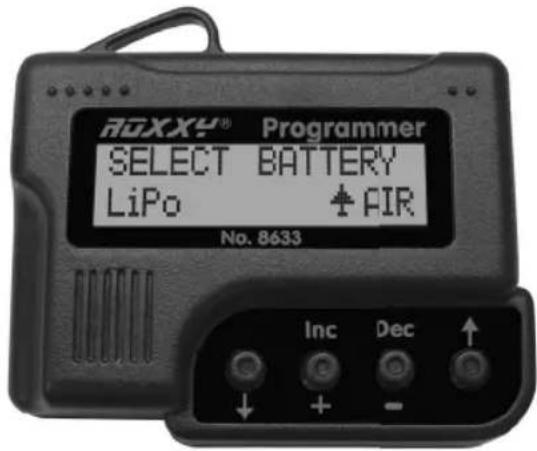

Navigating using the Programmer
The Programmer could hardly be easier to use: the outer arrow buttons are used to move up or down in order to select the programming modes of your choice. You can also use the arrow buttons to select the model type by holding both buttons pressed in. The purpose of the two centre buttons DEC (-) and INC (+) is to select and/or change settings.
6.1. Overview of programming facilities
With a few exceptions, all the programming points are laid out in the same way. To help you understand the arrangement, all the values are listed in the table printed below.
| Helicopter Boat/Car Aircraft | ||
| Select Battery Select Battery Select Battery | ||
| Cut Off Voltage Cut Off Voltage Cut Off Voltage | ||
| Cut Off Type Cut Off Type Cut Off Type | ||
| Motor Direction Motor Direction Motor Direction | ||
| Advance Timing Advance Timing Advance Timing | ||
| Acceleration Acceleration Acceleration | ||
| Start Power Start Power Start Power | ||
| Response of Governor Reverse Function Air Brake Type | ||
| Governor On/ Off | Motor pole Num Airbrake On/Off | |
| Motor pole Num Gear Ratio Motor pole Num | ||
| Gear Ratio | Max. RPM | Gear Ratio |
| Max. RPM Average RPM | Max. RPM | |
| Average RPM Down Load | Average RPM | |
| Down Load | Restore Mem. | Down Load |
| Restore Mem. | Backup Mem. | Restore Mem. |
| Backup Mem. | Backup Mem. | |
7. Programming in detail
1. Battery Type
SELECT BATTERY
LiPo + AIR
Use the DEC or INC button to set the desired battery type. When you have selected the new battery type you may find that the previously set "CUT OFF VOLTAGE" and "CUT OFF TYPE" parameters have changed. The DEC and INC buttons are always used to set the modes.
2. Cut Off Voltage
CUT OFF VOLTAGE AUTO HELI
The Cut Off Voltage varies according to the battery type you have set. If you have selected a LiPo battery, the speed controller switches off at 3V per cell in Auto mode; if you have selected a NiCd pack, the unit switches off at 5.5V (variable cut-off type). However, you can set the value yourself using the DEC and INC buttons; the range extends from 4.5V to 33.0V .
3. Cut Off Type
CUT OFF TYPE SOFT OFF HELI
In Cut Off Type mode you can select the cut-off method when battery voltage falls to the set threshold. The options are "Soft Off" or "Hard Off". Use the DEC and INC buttons to set the modes.
4. Motor Direction
MOTOR DIRECTION Reverse HELI
In Motor Direction mode you can select the direction of rotation of your motor: the two options are normal and reversed.
5. Advance Timing
ADVANCE TIMING 8 HELI
Advance Timing is an alternative term for motor timing. This mode alters the advance of the rotational fi eld, which has a similar effect to "advancing the ignition point". In general terms a setting of 8^ is suitable for most motors. If you wish to use a special set-up for your motor, we recommend the following ranges of values: 0^ to 10^ for in-runner motors, and 15^ to 25^ for out-runner motors.
6. Acceleration
ACCELERATION Highest. HELI
In Acceleration mode you can set how fast the controller runs up to maximum speed. This is important if the throttle function is assigned to a switch, as it determines the delay, i.e. the speed with which the motor ramps up to "full-throttle".
Example: Lowest acceleration or Highest acceleration.
Variable parameters:
Lowest / Low / Normal / High / Highest, set using the DEC and INC buttons.
7. Start Power
START POWER Lowest HELI
In the Start Power menu you can set the level of power (torque) which the motor produces initially, i.e. from a stand-still. If you are using the controller in a model helicopter, the value should be small in order to avoid premature gear wear. The available values are Lowest / Low / Normal / High / Highest.
8. Air Brake Type
AIR BRAKE TYPE Fast AIR
In Air mode (model aircraft) it is possible to adjust the effect of the motor brake, and thereby determine whether the motor comes to a halt gently (soft) or abruptly (hard). The available options are Slow / Normal / Fast, and can be selected using the DEC and INC buttons.
9. Air Brake On/Off - Air mode only
AIR BRAKE On/Off On +AIR
This menu point is used for switching the motor brake on or off.

- Reverse function (Boat and Car modes only)
REVERSE FUNCTION Two Way BOAT
In Boat or Car mode the Reverse function is used for selecting whether the motor works only in one direction of rotation, or in forward and reverse. In "One Way" mode (only one direction of rotation) the motor's direction of rotation can also be selected: the two options are forward and reverse. In "Two Way" mode the speed controller is set up for forward / reverse operation.
Caution: changing the direction or motor rotation may cause the cancellation of other settings.
11. Governor Response - Helicopter mode only
RESPONSE Normal
OF GOV HELI
This mode is used for setting the characteristics of the speed controller in speed governor (regulator) mode. The available options are Slowest / Slow / Normal / Fast / Fastest.
Caution: the faster the value you select, the higher the current drawn from the battery. We recommend that you select a fairly low setting in order to avoid premature damage to the speed controller and/or the flight battery.
12. Governor On / Off - Helicopter mode only
GOVERNER ON/OFF OFF HELI
This mode is used for switching speed governor (regulator) operation on and off. Governor mode stabilises the pre-set rotational speed and keeps it virtually constant. The options are: "On" mode for stabilised, or "Off" mode for non-stabilised.
13. Motor Pole Number
MOTOR POLE NUM 2 POLE HELI
In Motor Pole Number mode you can enter the number of poles in your motor. This value is important for indicating the exact rotational speed. The available range extends from 2 to 36 poles.
14. Gear Ratio
GEAR RATIO 1.0:1 HELI
This mode allows you to enter the individual gearbox ratio you are using. The value for rotational speed indication is calculated using the number of motor poles and the gearbox reduction ratio. The available range of values is from 1.0:1 to 25.0:1.
15. Max. RPM & Average RPM
MAXIMUM RPM 01881 RPM T HELI
AVERAGE RPM 019774 RPN HELI
This mode shows you the maximum and average rotational speeds recorded during the last flight, taking into account the values set under Points 14 and 15.
16. Down Load
DOWN LOAD REALLY? No HELI
Download mode is used for writing (transferring) set values to the speed controller. Press the INC button to start the process, and the Programmer then beeps once every second until the procedure is complete. If you wish to interrupt the process, simply press the DEC button.
17. Restore Memory
RESTORE MEMORY REALLY? No NEHLI
Restore Memory is used to access values which have been stored in the Programmer's own memory. Press the INC button to start the process, and the Programmer then beeps once every second until the procedure is complete. If you wish to interrupt the process, simply press the DEC button.
18. Backup Memory
BACKUP MEMORY REALLY? No HELI
Backup Memory mode allows you to store permanently the selected values in the Programmer's integral memory. Press the INC button to start the process, and the Programmer then beeps once every second until the procedure is complete. The values set on the speed controller itself are not affected by this action. If you wish to interrupt the process, simply press the DEC button.

Contenu
- Introduction
CUT OFF TYPE SOFT OFF HELI
6. Acceleration (acceleration)
ACCELERATION Highest. HELI
1. Battery type (Tipo battery)
SELECT BATTERY LiPo + AIR
OUT OFF TYPE SOFT Off HELI
5. Advance Timing (Timing Motore)
ADVANCE TIMING 8 HELI
CUT OFF TYPE SOFT OFF HELI
- Advance Timing (timing motor)
ADVANCE TIMING 8 HELI
ACCELERATION Highest. HELI
CUT OFF TYPE SOFT OFF HELI
V Cut Off Type (typ odpojeni motoru) muzete nastavit typ odpojeni motoru pri nizkem napeti. Muzete zvolit mezi Soft Off a Hard Off. Mody Ize nastavit opet pomoci tlaitek DEC a INC.
- Motor Direction (smér otáčeni motoru)
MOTOR DIRECTION Reverse HELI
ADVANCE TIMING 8 HELI
- Response of Governor (charakteristika regulace) pouze u vrtulniku
RESPONSE OF GOV Normal HELI
Errors and omissions excepted.
Technical modifications reserved.
Copyright Multiplex Modellsport 2015
Duplication and copying of the text, in whole or in part,
is only permitted with the prior written approval of