
EB5300TH - Leaf blower MAKITA - Free user manual and instructions
Find the device manual for free EB5300TH MAKITA in PDF.

| Product type | Thermal leaf blower |
| Brand | Makita |
| Model | EB5300TH |
| Dimensions (without tube) | 320 mm x 450 mm x 475 mm |
| Weight (dry, without tube) | 8,9 kg |
| Engine type | Single-cylinder, 4-stroke, air-cooled |
| Displacement | 52,5 cm³ |
| Maximum speed | 6 400 min⁻¹ |
| Idle speed | 2 800 min⁻¹ |
| Air speed (long tube, round nozzle) | 81 m/s |
| Air flow | 15 m³/min |
| Fuel | Automotive gasoline (unleaded) |
| Fuel tank capacity | 1 800 cm³ |
| Engine oil | SAE 10W-30 (API SF or higher) |
| Engine oil capacity | 140 cm³ |
| Spark plug | NGK CMR6H (gap 0.7-0.8 mm) |
| Sound pressure level | 96,0 dB(A) |
| Sound power level | 102,5 dB(A) |
| Vibrations (right handle, long tube, round nozzle) | 2,2 m/s² |
| Safety | Emergency stop, accelerator lock, accidental restart protection |
| Recommended maintenance | Air filter cleaning, oil change every 50 h, spark plug inspection |
Frequently Asked Questions - EB5300TH MAKITA
User questions about EB5300TH MAKITA
0 question about this device. Answer the ones you know or ask your own.
Ask a new question about this device
Download the instructions for your Leaf blower in PDF format for free! Find your manual EB5300TH - MAKITA and take your electronic device back in hand. On this page are published all the documents necessary for the use of your device. EB5300TH by MAKITA.
USER MANUAL EB5300TH MAKITA
IMPORTANT SAFETY INSTRUCTIONS. 3
PARTS DESCRIPTION 7
ASSEMBLY 9
BEFORE STARTING THE ENGINE. 10
OPERATION 11
MAINTENANCE. 16
TROUBLESHOOTING 23
SPECIFICATIONS
| Model: EB5300TH EB5300WH | |||
| Throttle type Tube throttle Hip throttle | |||
| Dry weight | without blower pipe / with cusion | 8.9 kg 9.1 kg | |
| with blower pipe 9.8 kg - 10.0 kg | 10.1 kg - 10.3 kg | ||
| Dimension (without blower pipe, L x W x H) 320 mm x 450 mm x 475 mm 320 mm x 510 mm x 475 mm | |||
| Air velocity (with long pipe, circular nozzle) 81 m/s | |||
| (with short pipe, circular nozzle) | 82 m/s | ||
| Air volume flow rate | (with long pipe, circular nozzle) | 15 m³/minute | |
| (with short pipe, circular nozzle) | 15 m³/minute | ||
| Maximum engine speed 6,400 min | -1 | ||
| Idling speed | 2,800 min-1 | ||
| Engine displacement | 52.5 cm³ | ||
| Engine type | Air cooled, 4-stroke, single cylinder | ||
| Fuel | Automobile gasoline | ||
| Fuel tank capacity | 1,800 cm³ | ||
| Engine oil | API grade SF class or higher, SAE 10W-30 oil (automobile 4-stroke engine oil) | ||
| Engine oil volume | 140 cm³ | ||
| Carburetor | Diaphragm type | ||
| Spark plug | NGK CMR6H | ||
| Electrode gap | 0.7 mm - 0.8 mm | ||
Due to our continuing program of research and development, the specifications herein are subject to change without notice.
Specifications may differ from country to country.
The weight may differ depending on the attachment(s).
Vibration
| Model | EB5300TH | EB5300WH | ||||
| Vibration per EN15503 | Right handle | alve eq | Long pipe | with circular nozzle | 2.2 (m/s2) | 2.3 (m/s2) |
| with flat nozzle | 2.9 (m/s2) | 4.0 (m/s2) | ||||
| Short pipe | with circular nozzle | 2.2 (m/s2) | 2.3 (m/s2) | |||
| with flat nozzle | 2.5 (m/s2) | 3.6 (m/s2) | ||||
| Uncertainty K | 0.6 (m/s2) | 1.9 (m/s2) | ||||
| Left handle (cotrol arm) | alve eq | Long pipe | with circular nozzle | - | 0.5 (m/s2) | |
| with flat nozzle | - | 0.5 (m/s2) | ||||
| Short pipe | with circular nozzle | - | 0.5 (m/s2) | |||
| with flat nozzle | - | 0.5 (m/s2) | ||||
| Uncertainty K | - | 0.3 (m/s2) | ||||
Noise
| Model EB5300TH EB5300WH | |||
| Sound pressure level average to EN15503 | L PA eq | 96.0 (dB(A)) 96.0 (dB(A)) | |
| Uncertainty K 0.4 (dB(A)) 0.4 (dB(A)) | |||
| Sound power level average to EN15503 | L WA eq | 102.5 (dB(A)) 102.5 (dB(A)) | |
| Uncertainty K 1.6 (dB(A)) 1.6 (dB(A)) | |||
Symbols
The following show the symbols used for the equipment. Be sure that you understand their meaning before use.
| Take particular care and attention. |
| Read the instruction manual. |
| Forbidden! |
| No smoking. |
| No open flame. |
| Wear protective gloves. |
| Wear eye and ear protection. |
| Hot surfaces - Burns to fingers or hands. |
| Keep bystanders away. |
| Keep the area of operation clear of all persons and pets. |
| Fuel (gasoline) |
| Engine manual start. |
| Stop the engine. |
| First aid |
| On/Start |
| Off/Stop |
| Long hair may cause entanglement accident. |
EC Declaration of Conformity
For European countries only
The EC declaration of conformity is included as Annex A to this instruction manual.
IMPORTANT SAFETY INSTRUCTIONS
General instructions
- To ensure correct and safe operation, the user must read, understand and follow this instruction manual to assure familiarity with the handling of the blower. Users insufficiently informed will risk danger to themselves as well as others due to improper handling.
- It is recommended only to lend the blower to people who have proven to be experienced with blowers.
- Always hand over the instruction manual when lending the blower.
- First-time users should ask the dealer for basic instructions to familiarize oneself with the handling of a blower.
- Children and young persons aged under 18 years must not be allowed to operate the blower. Persons over the age of 16 years may however use the tool for the purpose of being trained only while under the direct supervision of a qualified trainer.
- Use blowers with the utmost care and attention.
- Operate the blower only if you are in good physical condition.
- Perform all work conscientiously and carefully. The user has to accept responsibility for others.
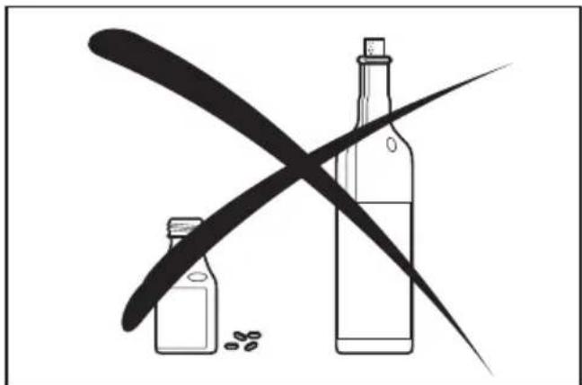
- Never use the blower while under the influence of alcohol or drugs.
- Do not use the unit when you are tired.
- Save these instructions for future reference.
-
Observe and follow all relevant accident prevention instructions issued by the trade associations and by insurance companies. Do not perform any modifications to the blower as this will risk your safety.
-
Never make modification on the equipment. It may cause dangerous accidents or personal injury.
Personal protective equipment
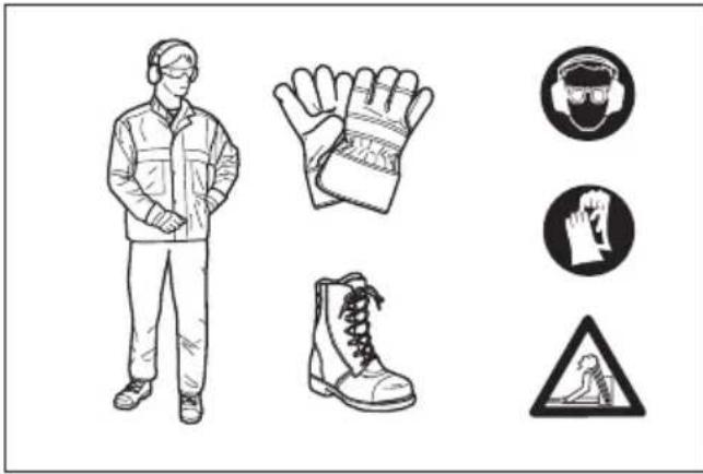
- The clothing worn should be functional and appropriate, i.e., it should be tight fitting but not cause a hindrance. Do not wear jewelry, clothing or long hair which could be drawn into the air intake.
- In order to avoid head-, eye-, hand- or foot injuries as well as to protect your hearing the following protective equipment and protective clothing must be used during operation of the blower.
- Clothing must be sturdy and snug-fitting, but allow complete freedom of movement. Avoid loose-fitting jackets, flared or cuffed pants, scarves, unconfined long hair or anything that could be drawn into the air intake. Wear overalls or long pants to protect your legs. Do not wear shorts.
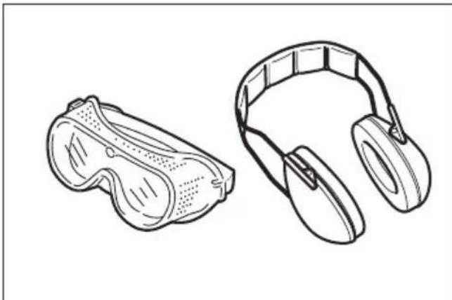
- Generally, engine products are noisy and their noise may damage your hearing. Wear sound barriers (ear plugs or ear mufflers) to protect your hearing. Continual and regular users should have their hearing checked regularly.
- Use of gloves when working with the blower is recommended. Wear sturdy shoes with non-slip soles.
-
Proper eye protection is a must. Even though the discharge is directed away from the operator, ricochets and bounce-backs can occur during blower operation.
-
Never operate a blower unless wearing goggles or properly fitted safety glasses with adequate top and side protection which comply with EN166 and regulations in your country.
- To reduce the risk of injury associated with the inhalation of dust, use face filter mask in dusty conditions.
Intended use
The tool is intended for blowing dust.
Starting up the blower
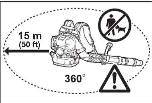
- Make sure that there are no children or other people within a working range of 15 meters, also pay attention to any animals near by.
-
Before operating, always check that the blower is safe for operation:
-
Check the security of the throttle lever. The throttle lever should be checked for smooth and easy action.
- Check for proper functioning of the throttle lever lock.
-
Check for clean and dry handles and test the function of the I-O switch. Keep handles free of oil and fuel.
-
Start the blower only in accordance with the instructions. Do not use any other methods for starting the engine.
- Use the blower and the tools supplied only for applications specified.
-
Start the blower engine only after the entire tool has been assembled. Operation of the tool is permitted only after all the appropriate accessories are attached.
-
The engine is to be switched off immediately if there are any engine problems.
- When working with the blower, always wrap your fingers tightly around the handle, keeping the control handle cradled between your thumb and forefinger. Keep your hand in this position to have your machine under control at all times. Make sure your control handle is in good condition and free of moisture, pitch, oil or grease.
- Always ensure a safe, well-balanced footing.
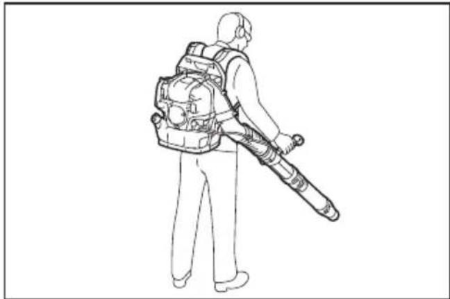
- Carry the blower properly on both shoulders during operation. Do not carry the blower with only one shoulder strap. Otherwise personal injury may result.
- Operate the blower in such a manner as to avoid inhalation of the exhaust gases. Never run the engine in enclosed rooms (risk of suffocation and gas poisoning). Carbon monoxide is an odorless gas. Always ensure there is adequate ventilation.
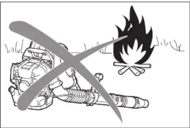
- Switch off the engine when resting or leaving the blower unattended. Place it in a safe location prevent danger to others, setting fire to combustible materials, or damage to the machine.
- Never lay the hot blower onto dry grass or onto any combustible materials.
- All protective parts and guards supplied with the machine must be used during operation.
- Never operate the engine with a faulty exhaust muffler.
Transport
- Shut off the engine during transport.
- Position the blower safely during car or truck transportation to avoid fuel leakage.
- When transporting the blower, ensure that the fuel tank is completely empty.
- Lift the blower with holding carry handle when you carry it. Do not drag the blower by nozzle, pipe or other parts.
- Hold the blower firmly during transportation.
- When transport the blower, bend your knee and make sure you do not damage your shoulder and lower back.
Refuelling
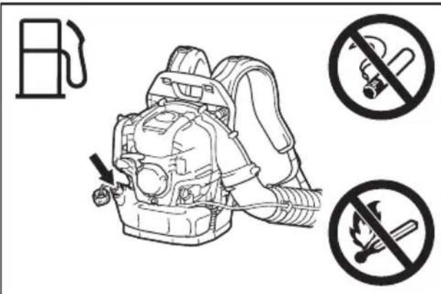
- Stop the engine during refuelling, keep well away from open flame and do not smoke.
- Avoid skin contact with petroleum products. Do not inhale fuel vapor. Always wear protective gloves during refuelling. Change and clean protective clothing at regular intervals.
- Take care not to spill either fuel or oil in order to prevent soil contamination (environmental protection). Clean the blower immediately after fuel has been spilt. Allow wet cloths to dry before disposing in properly, covered container to prevent spontaneous combustion.
- Avoid any fuel contact with your clothing. Change your clothing immediately if fuel has been spilled on it (fire hazard).
- Inspect the fuel cap at regular intervals making sure that it stays securely fastened.
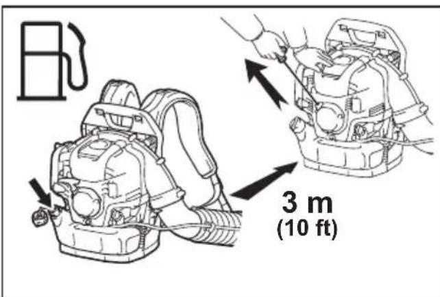
- Carefully tighten the fuel cap. Change locations to start the engine (at least 3 meters (10 ft) away from the place of refuelling).
- Never refuel in closed rooms. Fuel vapors accumulate at ground level (risk of explosions).
- Only transport and store fuel in approved containers. Make sure stored fuel is not accessible to children.
- Do not attempt to refuel a hot or a running engine.
- Do not refuel more than the amount defined in "SPECIFICATIONS".
Method of operation
- Use the blower only in good light and visibility. Beware of slippery or wet areas, ice and snow (risk of slipping), and narrow space. Always ensure a safe footing.
- Never work on unstable surfaces or steep terrain.
- Do not work from ladders or high places. Otherwise it may result in personal injury.
- To reduce the risk of personal injury, do not direct air blast towards bystanders, since the high pressure of the air flow could injure eyes and could blow small objects at great speed.
- Never insert any foreign object into the air intake of the machine or into the nozzle of the blower. It will damage the fan wheel and may cause serious injury to the operator or bystanders as a result of the object or broken parts being thrown out at high speed.
- Pay attention to the direction of the wind, i.e., do not work against the wind.
- To reduce the risk of stumbling and loss of control, do not walk backward while operating the machine.
- Always stop the engine before cleaning or servicing the unit or replacing parts.
- Take a rest to prevent loss of control caused by fatigue. We recommend to taking a 10 to 20-minute rest every hour.
- Do not operate the machine near the windows, etc.
- To reduce physical influence from vibration and/or damage to the ears, operate the machine at low speed if possible and limit the time of operation.
- Operate the machine only at reasonable hours. Do not operate the blower in the morning or late at night when people might be disturbed.
- It is recommended for using rakes and brooms to loosen debris before blowing.
- Before blowing, slightly dampen surfaces in dusty conditions or use water mist sprayer if necessary.
- Adjust the length of the blower nozzle so that the stream can work close to the ground.
- To reduce sound levels, limit the number of pieces of equipment used at any one time.
- After using blowers and other equipment, CLEAN UP! Dispos of debris in trash receptacles.
- Do not accelerate the engine more than necessary. Blown object may result in personal injury.
- The exhaust muffler becomes hot during the operation. Do not touch hot exhaust muffler, skin burn may result.
- Do not operate the machine in explosive atmospheres, such as in the presence of flammable liquids, gases or dust. The machine creates sparks which may ignite the dust or fumes.
Maintenance instructions
- Be kind to the environment. Operate the blower with as little noise and pollution as possible. In particular, check the correct adjustment of the carburetor.
- Clean the blower at regular intervals and check that all screws and nuts are securely tightened.
- Never service or store the blower in the vicinity of open flames, sparks, etc.
- Always store the blower in a well-ventilated locked room and with the fuel tank emptied.
- The performance of maintenance or repair work by the user is limited to those activities as described in this instruction manual. All other work is to be done by Authorized Service Agents.
- Use only genuine spare parts and accessories supplied by Makita. Use of non-approved accessories and tools may result in accidents and injuries. Makita will not accept any liability for accidents or damage caused by the use of any non-approved attachment or accessories.
- Incorrect repair and poor maintenance can shorten the life of the equipment and increase the risk of accidents.
First aid
- In case of accident make sure that a well-stocked first-aid kit is available in the vicinity of the operations. Immediately replace any item taken from the first aid kit.
-
When asking for help, give the following information:
-
Place of the accident
- What happened
Number of injured persons
Nature of the injury
— Your name
PARTS DESCRIPTION

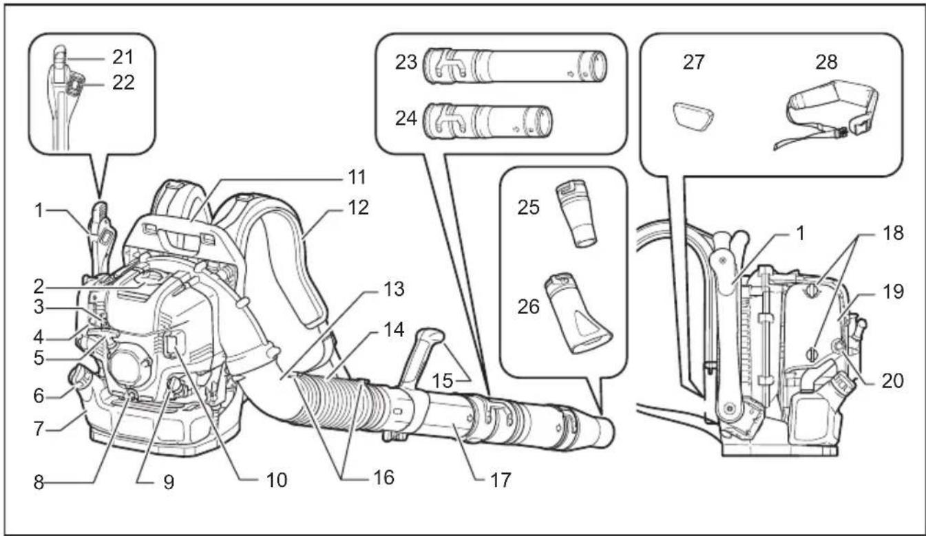
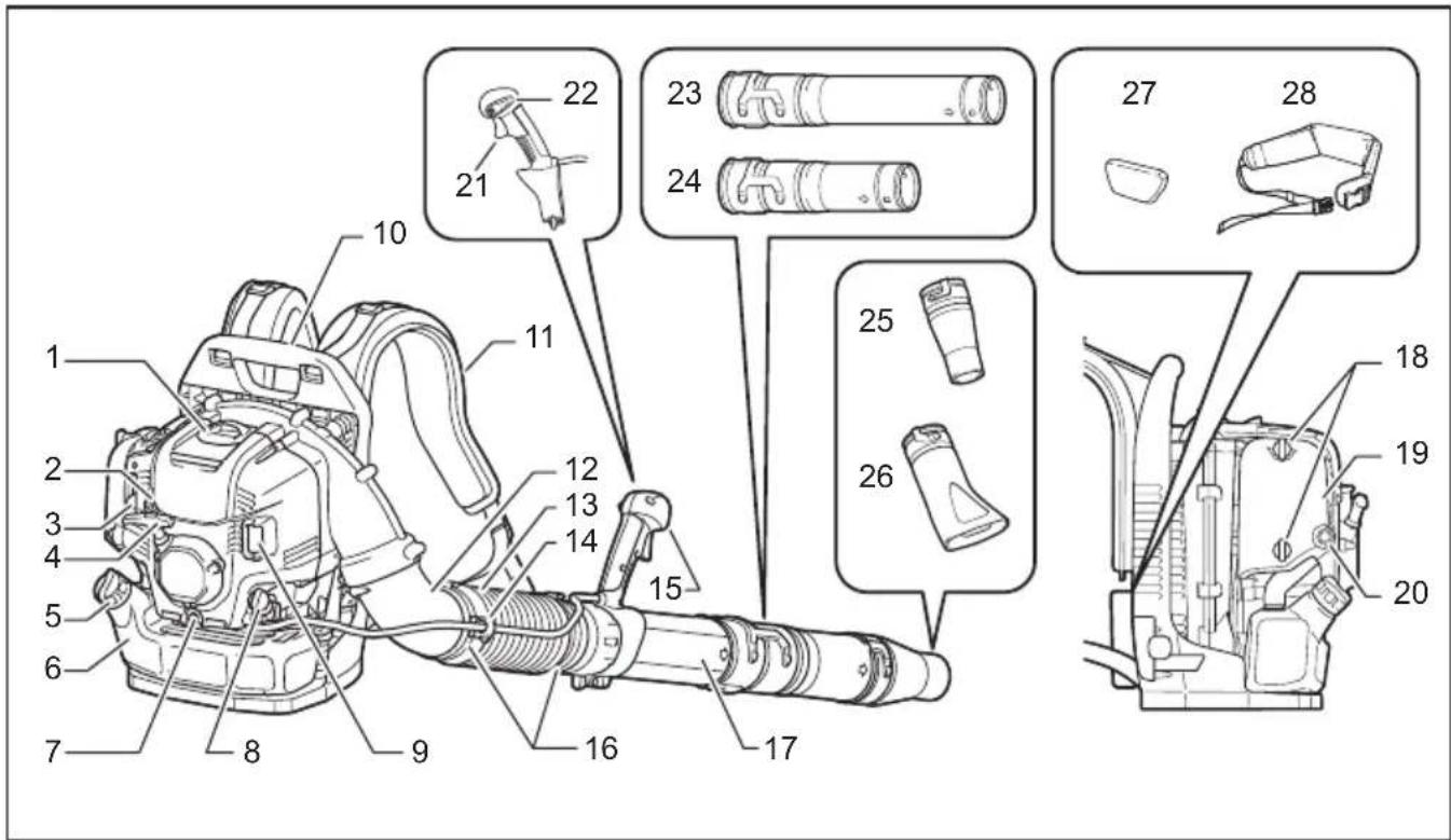
EB5300TH
| 1 | Spark plug cover | 9 | Muffler | 17 | Swivel pipe | 25 | Circular nozzle |
| 2 | Anti icing lever | 10 | Carry handle | 18 | Knob bolt (of air cleaner cover) | 26 F | at nozzle (optional accessory) |
| 3 | Choke lever | 11 | Shoulder strap | 19 | Air cleaner cover | 27 | Cushion (optional accessory) |
| 4 | Starter knob | 12 | Elbow | 20 | Primer pump | 28 | Hip belt (optional accessory) |
| 5 | Fuel tank cap | 13 | Flexible pipe | 21 | Throttle trigger | - | - |
| 6 | Fuel tank | 14 | Cable holder | 22 | Stop control lever | - | - |
| 7 | Oil drain bolt | 15 | Control handle | 23 | Long pipe (optional accessory) | - | - |
| 8 | Oil cap | 16 | Hose band | 24 | Short pipe (optional accessory) | - | - |
Standard accessories may differ from country to country.
| 1 | Control arm | 9 | Oil cap | 17 | Swivel pipe | 25 | Circular nozzle |
| 2 | Spark plug cover | 10 | Muffler | 18 | Knob bolt (of air cleaner cover) | 26 F | at nozzle (optional accessory) |
| 3 | Anti icing lever | 11 | Carry handle | 19 | Air cleaner cover | 27 | Cushion (optional accessory) |
| 4 | Choke lever | 12 | Shoulder strap | 20 | Primer pump | 28 | Hip belt (optional accessory) |
| 5 | Starter knob | 13 | Elbow | 21 | Throttle lever | - | - |
| 6 | Fuel tank cap | 14 | Flexible pipe | 22 | Stop switch | - | - |
| 7 | Fuel tank | 15 | Handle assembly | 23 | Long pipe (optional accessory) | - | - |
| 8 | Oil drain bolt | 16 | Hose band | 24 | Short pipe (optional accessory) | - | - |
Standard accessories may differ from country to country.
ASSEMBLY
CAUTION: Before performing any work on the blower, always stop the engine and pull the spark plug cap off the spark plug.
CAUTION: Start the blower only after having assembled it completely.
CAUTION: Always wear protective gloves.
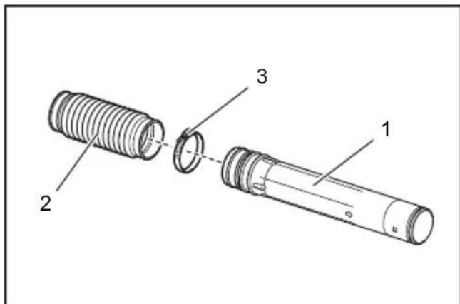
Assembling blower pipes
- Insert the swivel pipe into the flexible pipe and tighten them with the hose band.
-
Swivel pipe 2. Flexible pipe 3. Hose band
-
Loosen and remove the clamp screw.
- Clamp screw
For tube throttle model, be careful not to twist the cable on the control handle when attaching to the swivel pipe.
- Install the control handle / handle assembly onto the swivel pipe and tighten them with the clamp screw.
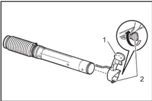
-
Control handle / handle assembly 2. Clamp screw
-
Attach the flexible pipe to the elbow
For tube throttle model: Insert the elbow to the flexible pipe. Attach the cable holder between the hose band and the flexible pipe. Tighten the cable holder, flexible pipe and elbow with the hose band. Set the control cable onto the cable holder, and close the cable holder.
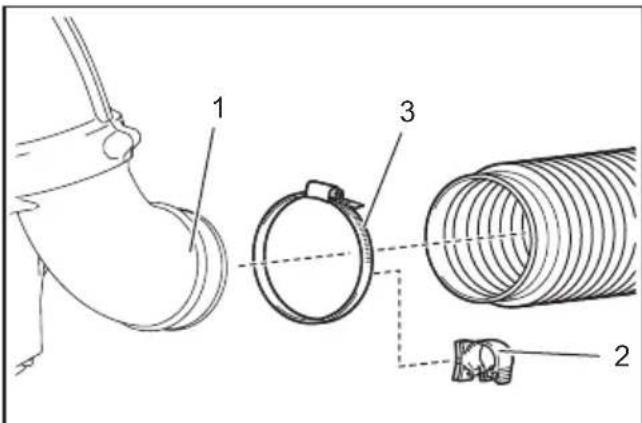
- Elbow 2. Cable holder 3. Hose band
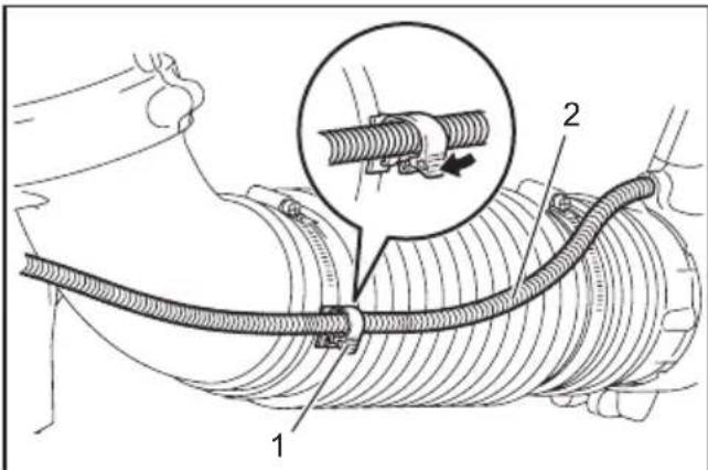
- Cable holder 2. Control cable
For hip throttle model: Insert the elbow to the flexible pipe. Tighten the flexible pipe and the elbow with the hose band.
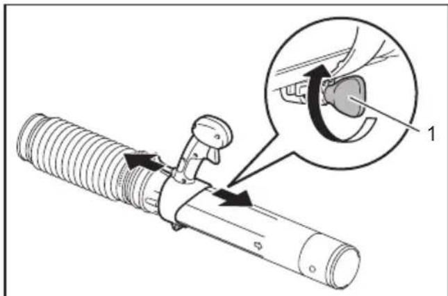
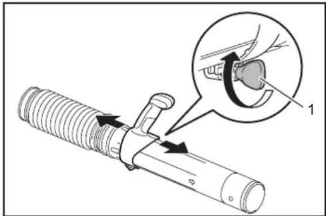
- Attach the long/short pipe to the swivel pipe. Turn the long/short pipe clockwise to lock it into place. Then attach the blower nozzle with the long/short pipe. Turn the blower nozzle clockwise to lock it into place.
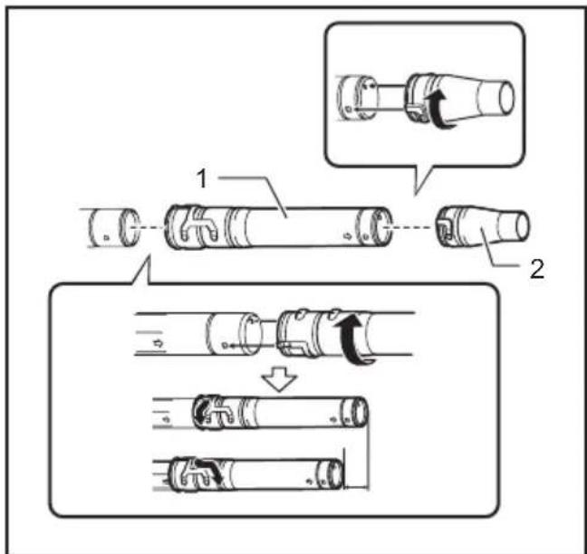
1. Long/short pipe 2. Blower nozzle
6. Make sure all clamps are tight. Check if the throttle valve moves correctly along with the throttle movement.
If the throttle cannot be fully pulled or the throttle does not return to the correct position, refer to the MAINTENANCE section for throttle valve adjustment.
BEFORE STARTING THE ENGINE
Checking and refill of engine oil
CAUTION: When refilling with engine oil, stop the engine and wait for the engine to cool down. Otherwise skin burn may result.
NOTICE: Use of deteriorated oil will cause irregular start-up.
NOTICE: Remove dust or dirt near the oil refill port before detaching the oil cap. Also, keep the detached oil cap free of sand or dust. Otherwise, any sand or dust adhering to the oil cap may cause irregular oil circulation or wear on the engine parts, which will result in troubles.
1. Upper limit mark 2. Lower limit mark
Inspection
Put the blower on a flat surface and remove the oil cap. Make sure that the oil level is within the upper and lower limit marks. If the oil is not up to the lower limit, fill up with new oil.
Change the oil whenever it becomes dirty or significantly changes color. (Refer to "Replacing engine oil" for the oil change procedure and frequency.)
Refill
Put the blower on a flat surface and remove the oil cap. Fill the oil up to the upper limit of the oil level gauge.
On average, engine oil needs to be added after every 20 hours of operation (every 10 - 15 refuellings).
Recommended oil
- Makita genuine 4-stroke engine oil or
- API grade SF class or higher, SAE 10W-30 oil (automobile 4-stroke engine oil)
Oil capacity
Oil capacity: approximately 140 ml
NOTICE: Store the blower in an upright position on flat surface. The oil gauge does not indicate correct amount of oil if the blower is leaned and oil is flown into the engine. It may result in filling too much oil.
NOTICE: Do not fill with excessive oil.
Excessive oil may spill from the breather of the air cleaner and make surrounding parts dirty, or white smoke may appear due to burning oil.
After refilling with oil
Wipe spilled oil with a rag.
Fuel supply
WARNING: When refuelling, stop the engine and wait for the engine to cool down. Otherwise ignition, fire, or skin burn may result.
WARNING: Fuel supply must be made in a place free of fire to prevent ignition or fire. Never bring the fire (smoking, etc.) near the place of fuel supply.
WARNING: Refuel on flat surface. Do not refuel on unstable place. Refuel in good light and visibility.
WARNING: Open the fuel tank cap slowly. The fuel may be spilled out by internal pressure.
WARNING: Take care not to spill the fuel. Wipe spilled fuel.
WARNING: Carry out fuel supply in a well-ventilated place.
WARNING: Refuel at open clear place.
WARNING: Handle the fuel with care.
CAUTION: Fuel sticking to the skin or entering an eye may cause allergies or irritation. When any physical abnormality is detected, consult the medical specialist immediately.
NOTICE: DO NOT put oil in the fuel tank.
Fuel
WARNING: Keep the machine and tank at a cool place free from direct sunshine.
WARNING: Never keep the fuel in a car.
The engine is a 4-stroke engine. Be sure to use an automobile gasoline (regular gasoline or premium gasoline).
NOTICE: Never use gasoline mixed with any oil such as 2 stroke oil or motor oil. Otherwise, it causes excessive carbon accumulation or mechanical troubles.
NOTE: Keep fuel in a special container in a well-ventilated and shaded area. Use fuel within a period of 4 weeks. Otherwise, fuel may deteriorate in one day.
Refuelling method
CAUTION: If there is any flaw or damage on the tank cap, replace it.
CAUTION: The tank cap wears out in course of time. Replace it every two to three years.
NOTICE: DO NOT put fuel in the oil fill port.
- Loosen the tank cap a little to release the tank pressure.
- Detach the tank cap, and refuel, with discharging air by tilting the fuel tank so that the refuel port is oriented upward. DO NOT fill fuel up to the top of the tank.
- After refuelling, securely tighten the tank cap.
OPERATION
Starting the engine
WARNING: Never attempt engine start in a place where the fuel has been supplied. It may cause ignition or fire. When starting the engine, keep a distance of at least 3 meters from fuelling place.
WARNING: Exhaust gas from the engine is toxic. Do not operate the engine in a poorly-ventilated place, such as in a tunnel, building, etc. Operating the engine in the poorly-ventilated place may cause poisoning by exhaust gas.
WARNING: In case of detection of any abnormality in sound, odor, vibration after starting, stop the engine immediately and carry out inspection. If the engine is operated without attending such abnormality, an accident may occur.
WARNING: Do not touch hot engine cover. Otherwise skin burn may result.
WARNING: Make sure that there is no fuel leakage before starting the engine.
WARNING: Make sure that the engine stops when the stop switch is set to "O" position.
When the engine is cold or after refuelling (cold start)
- Put the blower on a flat surface.
- I/O position
For tube throttle model: Set the stop control lever to "I" position.
1. Stop control lever
For hip throttle model: Set the stop switch to "l" position. And make sure that the throttle lever is set to low speed position.
1. Stop switch 2. Throttle lever
- Continue to push the primer pump until fuel comes into the primer pump.

1. Choke lever 2. Primer pump
NOTE: In general, fuel comes into the carburetor by 7 to 10 pushes.
NOTE: Even the primer pump is pushed excessively, an excess of gasoline returns to the fuel tank.
-
Lift the choke lever to the closed position.
-
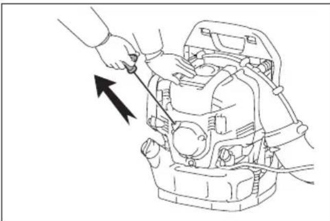
Put your left hand on the top of the blower and pull the starter handle slowly with your right hand until you feel the compression. Then pull the starter handle strongly.
NOTICE: Never pull the rope to the full extension.
NOTICE: Return the starter knob gently into the housing. Otherwise released starter knob may hit your body or it may not rewind appropriately.
NOTE: If the engine fires and stops, return the choke lever to the "OPEN" position and pull the starter handle several times to start the engine again.
- When the engine starts, down the choke lever to open position.
NOTE: Open the choke lever fully before pulling the throttle.
NOTE: In cold temperature or when the engine is not warm enough, never open the choke lever suddenly. Otherwise, the engine may stop.
- Warm-up for 2 to 3 minutes with engine speed idle or low.
- Warm-up is complete when quick engine acceleration from low rpm to full throttle is felt.
NOTE: If the operator keeps pulling the starter handle several times with the choke lever left in the "CLOSE" position, the engine may be difficult to start because of flooding of the fuel. In case of flooding of the fuel, remove the spark plug and pull the handle several times rapidly to discharge any excess fuel. Dry the spark plug electrode.
When the engine is warm (warm start)
CAUTION: Be careful not to burn your hand. Wear gloves when you start the engine.
- Put the blower on a flat surface.
- Push the primer pump several times.
- Make sure that the choke lever is open.
- Put your left hand on the top of the blower and pull the starter handle slowly with your right hand until you feel the compression. Then pull the starter handle strongly.
Stopping the engine
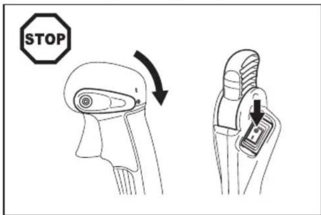
For tube throttle model: Release the throttle trigger and then set the stop control lever to "O" position.
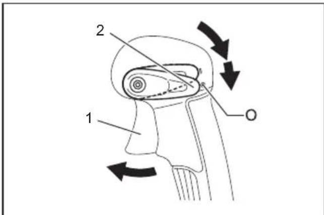
1. Throttle trigger 2. Stop control lever
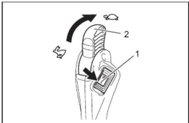
For hip throttle model: Set the throttle lever to the low speed position to reduce the engine speed. Then set the stop switch to "O" position.
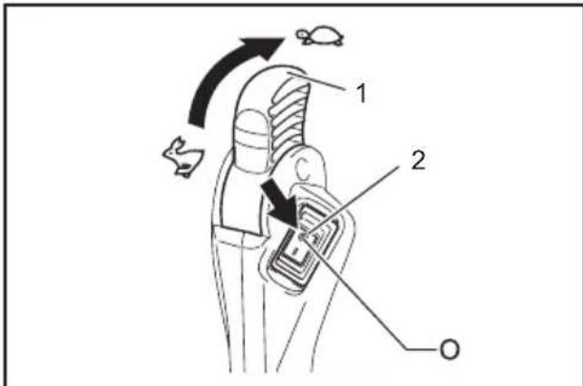
1. Throttle lever 2. Stop switch
Prevention from carburetor icing
NOTICE: When environmental temperature is higher than 10ircC , always return the lever to normal (sun mark) setting. Otherwise the engine may be damaged by overheating.
When the environmental temperature is low and humidity is high, water vapor may freeze inside the carburetor and the engine drives unsteadily (carburetor icing). Change the setting of the anti icing lever as follows if necessary.
- Remove the screw and pull out the anti-icing lever.
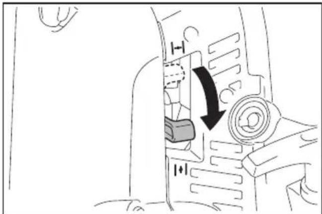
- Insert the anti-icing lever as follows:
Warmer environment than than 10ircC
Set the nub to the sun mark (warmer position).
10ircC or colder environment
Set the nub to the snow mark (anti-icing position).
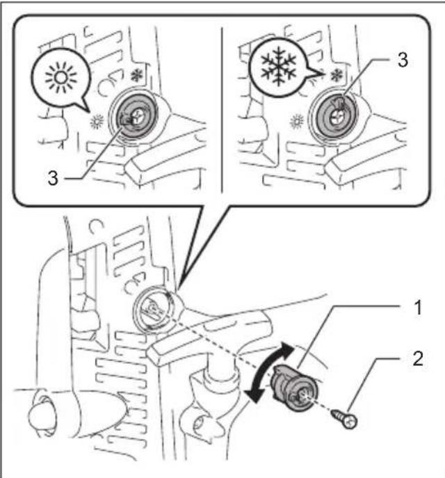
1. Anti-icing lever 2. Screw 3. Nub
- Tighten the screw.
Adjusting shoulder strap
- Adjust the shoulder strap to a length that is comfortable to work while carrying the blower. To tighten the strap, pull the end of the strap downwards.
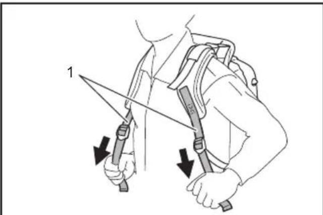
1. Shoulder strap
To loosen the strap, pull up the end of the fastener.
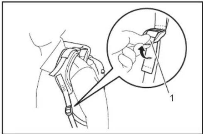
1. Fastener
1. Fastener
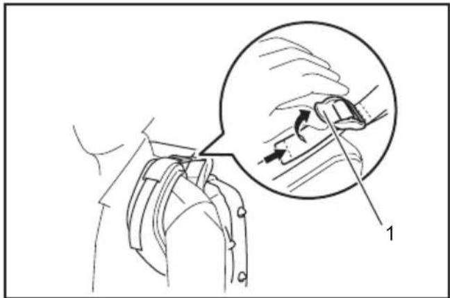
Roll up the end of the strap and hold it with the band.
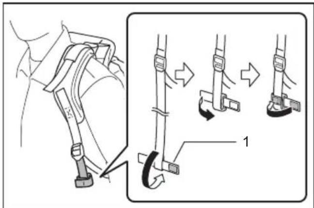
1.Band
Hip belt
Optional accessory
The hip belt enables the operator to carry the tool more stably.
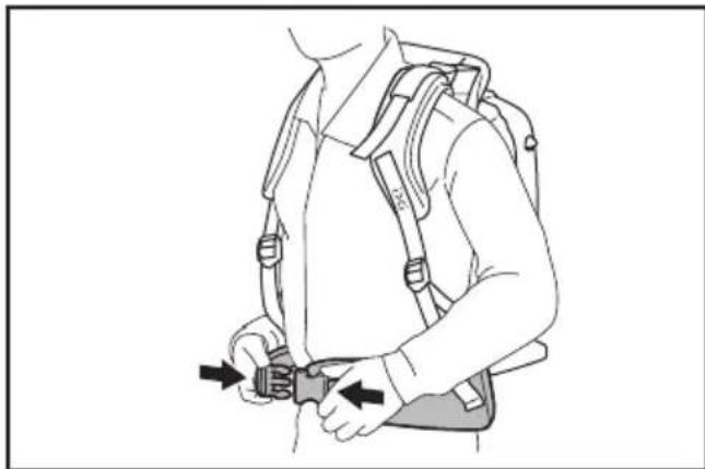
CAUTION: Make sure to release the hip belt buckle before unloading the blower.
- Pull the stabilizer strap until there are no space left between your back and the blower housing. To fasten the strap, pull the end of the strap downwards.
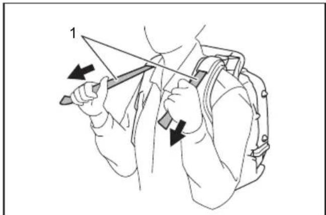
1. Stabilizer strap
Adjusting the control lever position
For tube throttle model: Move the control handle along the swivel pipe to the most comfortable position. Then tighten the control handle with the clamp screw.
1. Clamp screw
To loosen the strap, pull up the end of the fastener.
For hip throttle model: Move the handle assembly along the swivel pipe to the most comfortable position. Then tighten the handle with the clamp screw.
1. Clamp screw
1. Throttle trigger 2. Stop control lever
Adjust the angle of the control arm.
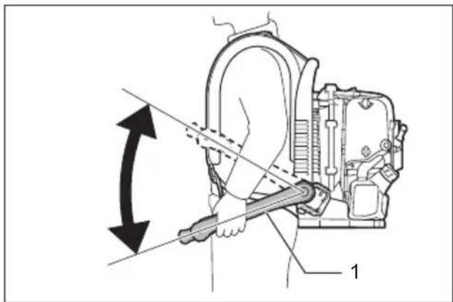
1. Control arm
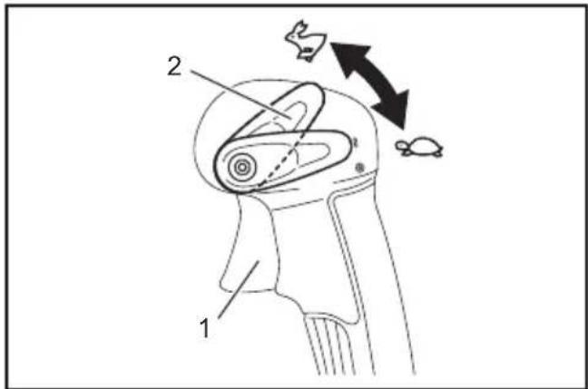
For hip throttle model: To increase the engine speed, turn the throttle lever to high speed. To decrease the engine speed, turn the throttle lever to low speed.
1. Throttle lever
Blower Operation
- While operating the blower, adjust the throttle trigger / throttle lever so that the wind force is appropriate for the work location and conditions.
- Adjusting engine speed.
For tube throttle model: Engine speed increases by pulling the throttle trigger. To decrease the engine speed, loosen the throttle trigger.
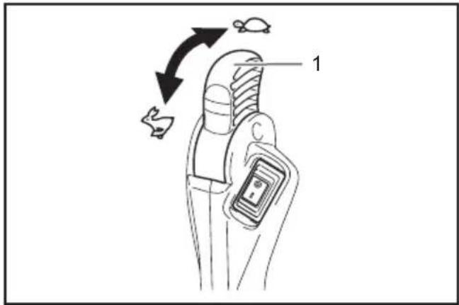
The cruise control function allows the operator to maintain a constant engine speed without pulling the trigger lever. To increase the engine speed, turn the stop control lever to high speed. To decrease the engine speed, turn the stop control lever to low speed.
Transporting the blower
CAUTION: When transporting the blower, be sure to stop the engine.
NOTICE: Do not sit or stand on the blower or put a heavy object on it. It may damage the machine.
NOTICE: Maintain the blower in an upright position whenever transporting or storing.
Transporting or storing in a position that is not upright may cause oil to spill inside the blower engine. This may result in oil leaks and white smoke from burning oil, and the air cleaner may become dirty with oil.
NOTICE: Do not drag the blower when transporting. Otherwise the blower housing may be damaged.
MAINTENANCE
CAUTION: Before inspection and maintenance, stop the engine and allow it to cool down. Remove the spark plug and plug cap. Otherwise the operator may suffer burn or serious injury due to an accidental start-up.
CAUTION: After inspection and maintenance, make sure that all parts are assembled.
Replacing engine oil
CAUTION: The engine main unit and engine oil still remain hot just after the engine is stopped. When replacing engine oil, make sure that the engine main unit and engine oil are sufficiently cooled down. Otherwise, there may remain a risk of scald. Allow sufficient time after stopping engine for the engine oil to return to the oil tank to ensure accurate reading of the oil amount.
CAUTION: If the oil filled above the limit, it may become dirty or may catch fire with white smoke.
NOTICE: Never discard replaced engine oil in garbage, ground or sewage. Disposal of oil is regulated by law. In disposal, always follow the relevant laws and regulations. For any points remaining unknown, contact Authorized Service Agent.
NOTICE: Oil will deteriorate even when it is kept unused. Perform inspection and replacement at regular intervals (replace with new oil every 6 months).
Deteriorated engine oil shortens the life of the sliding and rotating parts to a great extent. Be sure to check the period and quantity of replacement.
Interval of replacement
After first 20 operating hours, followed by every 50 operating hours
Recommended oil
- Makita genuine 4-stroke engine oil or
- API grade SF class or higher, SAE 10W-30 oil (automobile 4-stroke engine oil)
Oil replacement procedure
Change the oil as follows:
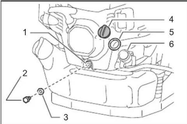
-
Drainage hole 2. Oil drain bolt 3. Gasket (alumi- num washer) 4. Oil cap 5. Oil cap gasket 6. Oil port
-
Put the blower down on a level surface.
- Put a waste oil container under the drainage hole to catch the oil as it drains out. The container should have a capacity of at least 140ml to catch all of the oil.
- Loosen the oil drain bolt to let the oil drain out. Be careful not to allow oil to get on the fuel tank or other parts.
NOTICE: Be careful not to lose the gasket (aluminum washer). Put the oil drain bolt in a location where it does not get dirt.
- Remove the oil cap. (Removing the oil cap allows the oil to drain easily.)
NOTICE: Be sure to set the oil cap down in a location where it does not get dirt.
- As the level of the oil being drained decreases, tilt the blower over on to the side with the drain so that the oil will completely drain out.
- After the oil has completely drained out, tighten the oil drain bolt securely. If the bolt is not tightly fastened, it may result in oil leakage.
NOTICE: Do not forget to put the gasket (aluminum washer) back on when reattaching the drain plug.
- Pour approximately 140ml oil into the oil refill port up to the upper limit mark.
1. Upper limit mark 2. Lower limit mark
- After filling with oil, tighten the oil cap securely to prevent oil leaks.
NOTICE: Do not forget to put the oil cap gasket back on when reattaching the oil cap.
Cleaning of air cleaner
WARNING: INFLAMMABLES STRICTLY PROHIBITED
Interval of Cleaning and Inspection
Daily (every 10 operating hours)
Cleaning procedure
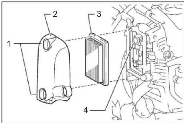
1. Knob bolts 2. Air cleaner cover 3. Element
4. Breather
- Loosen the knob bolts.
-
Remove the air cleaner cover.
-
Remove the element and clean off any dirt from the element with a cloth or air blow. Replace the element with a new one if it is damaged or very dirty.
NOTE: The element is a dry type and should not get wet. Never wash with water.
- Wipe off any oil around the breather with a rag or cloth.
- Install the element in the air cleaner case.
- Attach the air cleaner cover and tighten the knob bolts.
NOTICE: Clean the element several times a day, if excessive dust adheres to it due to dusty environment.
NOTICE: If operation continues with the element remaining not cleared of oil, oil in the air cleaner may fall outside, resulting in oil contamination.
Checking the spark plug
CAUTION: Do not touch the spark plug while the engine is running. Otherwise electrical shock may result.
CAUTION: Set the stop control lever/stop switch to OFF "O" position.
CAUTION: Check the spark plug cord regularly. If it is damaged or torn, replace it. Otherwise electrical shock may result.
NOTICE: When removing the spark plug, clean the spark plug and cylinder head first, so that no dirt, sand, etc will enter the cylinder.
NOTICE: Remove the spark plug after the engine has cooled down in order to avoid damaging the threaded hole in the cylinder.
NOTICE: Install the spark plug properly into the threaded hole. If installed at an angle, the threaded hole in the cylinder will get damaged.
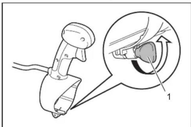
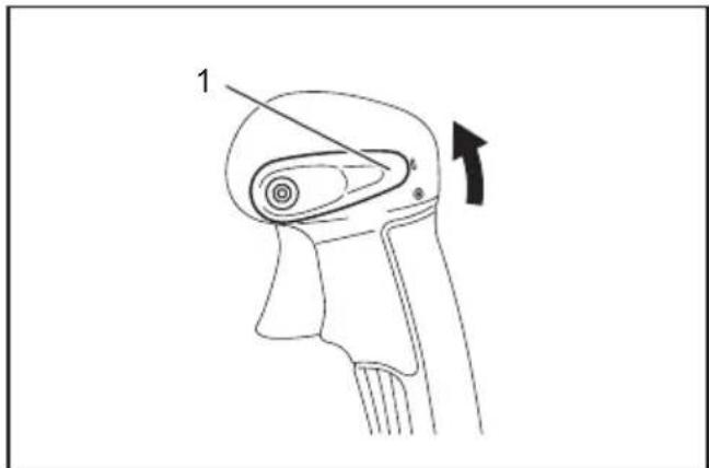
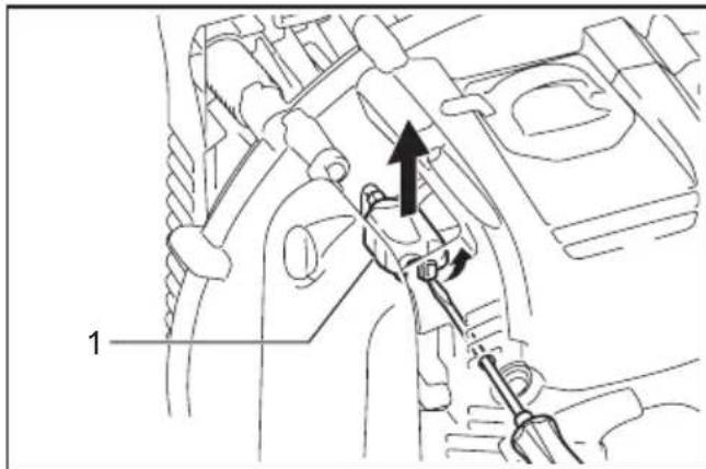
- To open the plug cover, lift it and make a half turn of it.
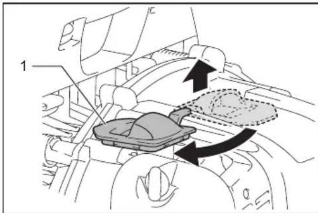
1. Plug cover
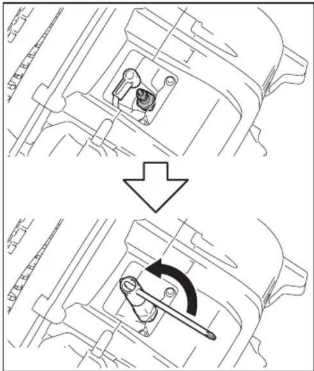
- Use the box wrench provided as an standard accessory to remove and install the spark plug.
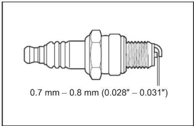
- The appropriate clearance between two electrodes of spark plug is 0.7 to 0.8mm . Adjust to the correct clearance when it is too wide or too narrow.
Clean thoroughly or replace the spark plug if it has accumulated carbon or contaminated.
For replacement, use NGK CMR6H.
- To close the plug cover, make a half turn of it, and press around the dented part.
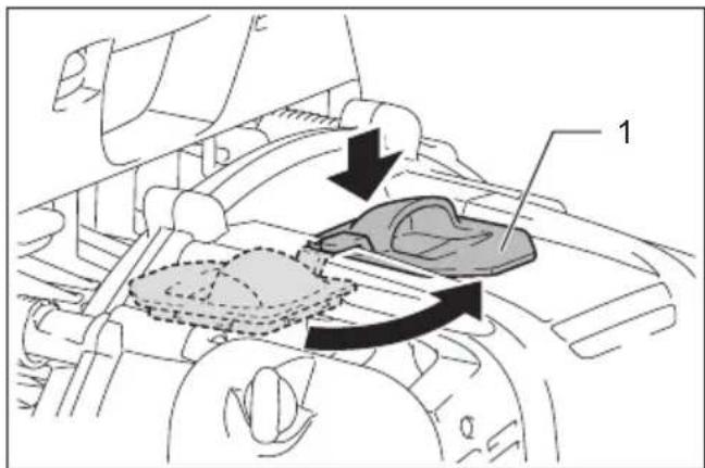
1. Plug cover
Cleaning the fuel filter
CAUTION: Make sure there is no damage on the fuel tank. If there are any damage on the fuel tank, ask authorized service center immediately for repair.
NOTICE: Clean the fuel filter regularly. Clogged fuel filter may cause difficulty of start-up or failure of engine speed increase.
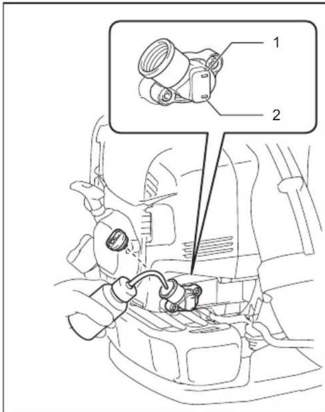
Check the fuel filter regularly as follows:
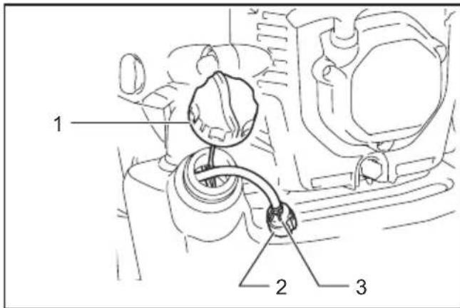
-
Fuel tank cap 2. Fuel filter 3. Hose clamp
-
Remove the fuel tank cap, drain the fuel to empty the tank. Check the tank inside for any foreign materials. If any, wipe clean such materials.
- Pull out the fuel filter with wire through the fuel filling port.
- If the fuel filter surface is contaminated, clean it with gasoline.
NOTICE: Follow the method specified by each local authority for disposing the gasoline used for cleaning the fuel filter.
NOTICE: Replace the fuel filter if it is excessively contaminated.
- After checking, cleaning or replacing, insert the fuel filter into the fuel pipe and fix it with the hose clamp. Reset the fuel filter in the fuel tank and tighten firmly the fuel tank cap.
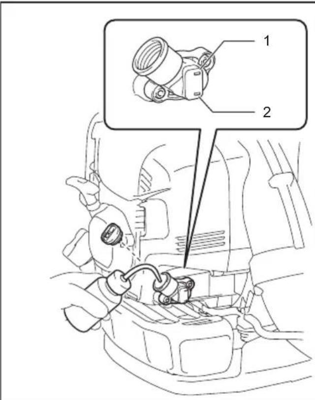
Adjustment of idling speed
CAUTION: The carburetor is factory adjusted. Never adjust other than idling speed. For other adjustments, ask your authorized service center.
Appropriate low-speed rotation is 2,800min-1 (rpm). If it is necessary to change the rotation speed, adjust the idle speed with a Phillips screwdriver. If the engine stops or runs unsteadily at idle, turn the adjusting screw to the right, and the idling speed increases. If the machine blows too strong at idle, turn the adjusting screw to the left, and the idling speed drops.
1.Idling adjusting screw
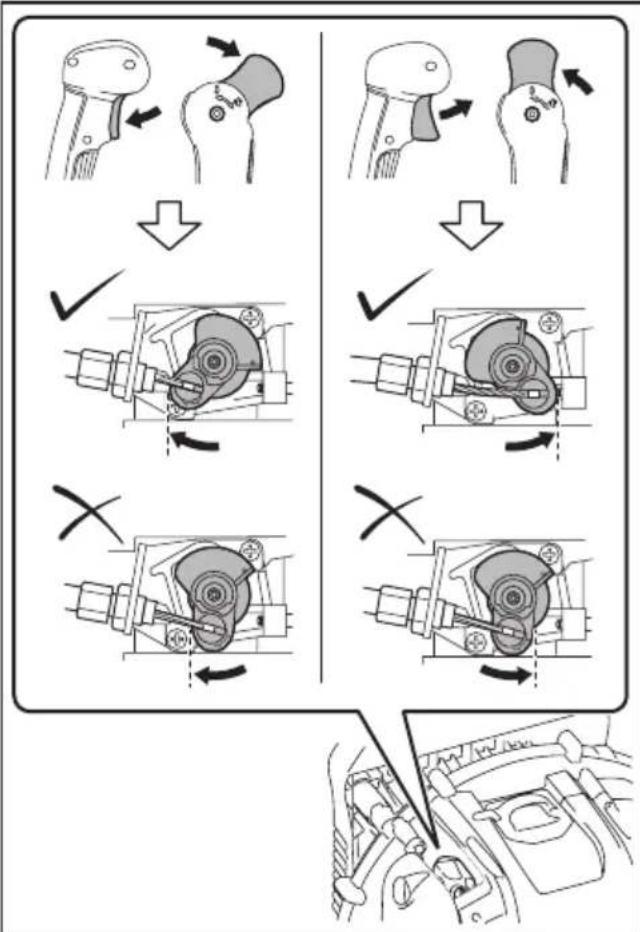
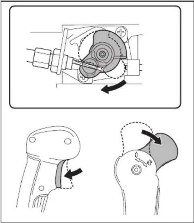
Checking throttle valve
If the control cable is bent or caught, the throttle valve does not contact with the idle adjusting screw, and it prevents the engine from proper idling. In such a case, reposition the control cable to ensure proper valve movement.

1. Throttle valve 2. Idling adjusting screw 3. Control cable 4. Throttle valve stopper
If the throttle valve does not touch the throttle valve stopper even you pull the throttle trigger fully or if the throttle valve does not touch the idling adjusting screw while idling, turn the cable adjusting bolt as follows:
- Loosen the fixing nut.
- If the throttle valve does not touch the throttle valve stopper, turn the cable adjusting bolt counterclockwise.
If the throttle valve does not touch the idling adjusting screw, turn the cable adjusting bolt clockwise.
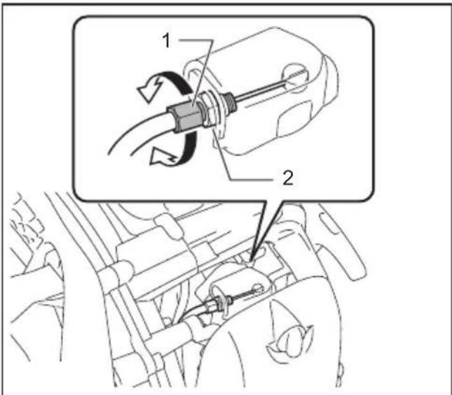
1. Cable adjusting bolt 2. Fixing nut
- Tighten the fixing nut to fasten the cable adjusting bolt.
- Check the movement of the throttle valve. The throttle valve comes to the position as illustrated when the throttle trigger/lever is pulled/turned.
Cleaning carburetor cover
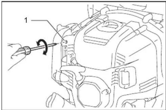
If the carburetor cover gets dirty and it is difficult to check the throttle valve, clean the carburetor cover as follows:
NOTICE: Never use gasoline, benzine, thinner, alcohol or the like for cleaning the carburetor cover. Otherwise it may be tarnished.
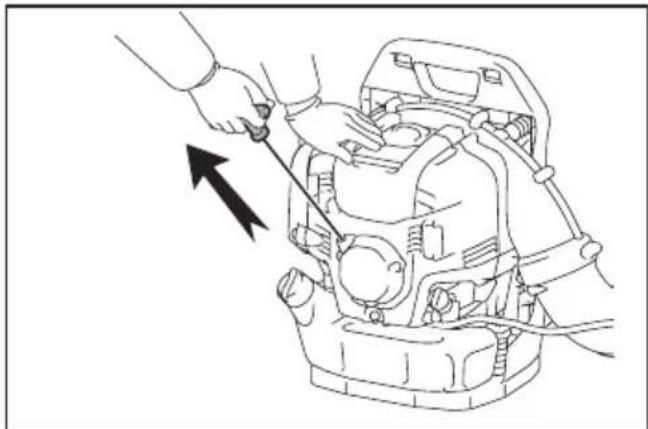
- Pass a slotted screwdriver through the hole on the engine cover. Release the clamp of the carburetor cover.
1. Carburetor cover
- Clean the carburetor cover.
NOTICE: Use wet clean cloth for cleaning the carburetor cover.
- Return the carburetor cover. Make sure the clamp of the carburetor cover clicks when it is set in place.
Inspecting bolts, nuts and screws and other parts
Retighten loose bolts, nuts, etc.
Check for fuel and oil leakage.
Replace damaged parts with new ones for safety operation.
Cleaning engine, cooling air inlet
Keep engine clean by wiping down with a cloth rag.
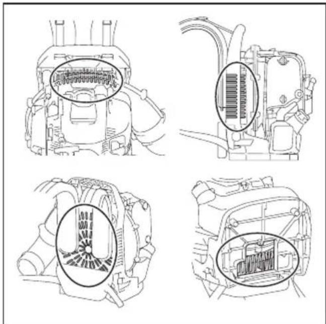
Keep the cylinder fins free of dust or dirt. Dust or dirt adhering to the fins may cause engine overheat and piston seizure.
Blowing air is taken in from the air inlet vent. When airflow drops down during operation, stop engine and inspect the air inlet vent for any blockages. Clean it if necessary. Such a blockage may cause overheat and damage the engine.
Replacing gaskets and packings
Replace gaskets and packings if the engine is disassembled.
Any maintenance of adjustment work that is not included and described in this manual is only to be performed by Authorized Service Agent.
Storage
WARNING: When draining the fuel, stop the engine and wait for the engine to cool down. Failure to do so may cause burns or fire.
CAUTION: When you store the machine for a long time, drain all fuel from the fuel tank and carburetor, and keep it at a dry and clean place.
Drain fuel from the fuel tank and carburetor before storing the machine as follows:
- Remove the fuel tank cap, and drain fuel completely. If there is any foreign materials remaining in the fuel tank, remove it completely.
- Pull out the fuel filter from the refill port using a wire.
- Push the primer pump until fuel is drained from there, and drain fuel coming into the fuel tank.
- Reset the filter to the fuel tank, and securely tighten the fuel tank cap.
- Then, continue to operate the engine until it stops.
- Remove the spark plug, and drip several drops of engine oil through the spark plug hole.
- Gently pull the starter handle so that engine oil will spread over the engine, and attach the spark plug.
- Keep the machine with its carry handle upside.
- Keep the drained fuel in a special container in a well-ventilated shade.
Fault location
| Fault System Observation Cause | |||
| Engine not starting or with difficulty | Ignition system | Ignition sparks. | Fault in fuel supply or compression system, mechanical defect. |
| No ignition sparks. STOP-switch | operated, wiring fault or short circuit, spark plug or connector defective, ignition module faulty. | ||
| Fuel supply | Fuel tank filled. | Incorrect choke position, carbur-rotor defective, fuel supply line bent or blocked, fuel dirty. | |
| Compression No compression when pulled over. | Cylinder bottom gasket defec-tive, crankshaft seals dam-aged, cylinder or piston rings defective or improper sealing of spark plug. | ||
| Mechanical fault Starter not engaging. Broken starter spring, broken | parts inside of the engine. | ||
| Warm start problems | - | Tank filled. Ignition sparks. | Carburetor contaminated, have it cleaned. |
| Engine starts but dies | Fuel supply | Tank filled. | Incorrect idling adjustment, carburetor contaminated. |
| Fuel tank vent defective, fuel supply line interrupted, cable or STOP-switch faulty. | |||
| Insufficient performance | Several systems may simulta-neously be affected | Engine idling poor. Air filter conta-minated, carbu-retor contaminated, muffler clogged, exhaust duct in the cylinder clogged. | |
Interval of inspection and maintenance
| - Before | operation | After fuelling | Daily (10h) | 50h | 200h | 600h or 2 years whichever earlier | Before storage | ||
| Engine oil | Inspect / refill | ○ | - | - | - | - | - | - | |
| Replace - | - | - | ○ (Note1) | - | - | - | |||
| Tightening parts (bolt, nut) | Inspect | ○ | - | - | - | - | - | - | |
| Cooling air inlet | Clean / inspect | ○ | - | - | - | - | - | - | |
| Fuel tank | Clean / inspect | ○ | - | - | - | - | - | - | |
| Drain fuel | - | - | - | - | - | - | ○ (Note3) | ||
| Throttle trigger / throttle lever | Check function | - | ○ | - | - | - | - | - | |
| Stopping the engine | Check function | - | ○ | - | - | - | - | - | |
| Adjustment of idling speed | Inspect / adjust | - | ○ | - | - | - | - | - | |
| Air cleaner | Clean | - | - | ○ | - | - | - | - | |
| Inspect / replace if necessary | - | - | - | - | ○ | - | - | ||
| - Before | operation | After fuelling | Daily (10h) 50h 200h 600h or | 2 years whichever earlier | Before storage | ||||
| Control cable | Inspect / adjust | - | - | ○ | ----- | ||||
| Inspect / replace if necessary | ----- | ○ (Note2) | - | - | |||||
| Spark plug Inspect / adjust gap if necessary | - | - | ○ | ----- | |||||
| Clean / replace if necessary | ----- | ○ | |||||||
| Plug cord Inspect / replace if necessary | ----- | ○ (Note2) | - | - | |||||
| Fuel pipe Inspect -- | ○ | ----- | |||||||
| Replace ---- | ○ (Note2) | - | - | ||||||
| Fuel filter Clean / replace if necessary | ----- | ○ | |||||||
| Oil tube Inspect ---- | ○ (Note2) | - | - | ||||||
| Valve clearance (intake valve and exhaust valve) | Inspect / adjust | ----- | ○ (Note2) | - | - | ||||
| Muffler Inspect / clean | ----- | ○ (Note2) | - | - | |||||
| Combustion chamber / valve / port | Inspect / clean | ----- | ○ (Note2) | - | - | ||||
| Engine Overhaul | ----- | ○ (Note2) | - | ||||||
| Carburetor Drain fuel | ----- | ○ (Note3) | |||||||
Note1: Perform initial replacement after 20h operation.
Note2: For inspection, request Authorized Service Agent or a machine shop.
Note3: After emptying the fuel tank, continue to run the engine and drain fuel in the carburetor.
TROUBLESHOOTING
Before asking for repairs, conduct your own inspection first. If you find a problem that is not explained in the manual, do not attempt to dismantle the tool. Instead, ask Makita Authorized Service Centers, always using Makita replacement parts for repairs.
| State of abnormality Probable cause | (malfunction) Remedy | |
| Engine does not start. Failure to operate | primer pump. Push 7 to 10 times. | |
| Low pulling speed of starter rope. Pull strongly. | ||
| Lack of fuel. Feed fuel. | ||
| Clogged fuel filter. Clean the fuel filter or replace with new one. | ||
| Bent fuel tube. Straighten the fuel tube. | ||
| Deteriorated fuel. Deteriorated fuel makes starting more difficult. Replace with new one. (Recommended replace-ment: 1 month) | ||
| Excessive suction of fuel. Set throttle lever from medium speed to high speed, and pull starter handle until engine starts. If engine will not start still, remove spark plug, make electrode dry, and reassemble them as they originally are. Then, start as specified. | ||
| Detached plug cap. Attach securely. | ||
| Contaminated spark plug. Clean the spark plug. | ||
| Abnormal clearance of spark plug. Adjust clearance. | ||
| Other abnormality of spark plug. Replace the spark plug. | ||
| Abnormal carburetor. Ask our authorized service center to inspect and repair it. | ||
| Cannot pull the starter knob. Ask our authorized service center to inspect and repair it. | ||
| Engine internal parts problem. Ask our authorized service center to inspect and repair it. | ||
| Engine stops soon. Engine speed does not increase. | Insufficient warm-up. Perform warm-up operation. | |
| Choke lever is set to "CLOSE" although engine is warmed up. Set to "OPEN". | ||
| Clogged fuel filter. Clean the fuel filter. | ||
| Contaminated or clogged air cleaner. Clean the air filter. | ||
| Detached control cable. Attach the control cable securely. | ||
| Engine internal parts problem. Ask our authorized service center to inspect and repair it. | ||
| Throttle does not return to idling speed. | Inproper throttle valve position. Reposition the control cable. Adjust the throttle valve position by turning the cable adjusting bolt. | |
| Engine does not stop. Run engine at idling, and set choke lever to "CLOSE". | Detached connector. Attach the connector securely. | |
| Abnormal electric system. Ask our authorized service center to inspect and repair it. |
TABLE DES MATIÈRES
SPECIFICATIONS 24
CONSIGNES DE SECURITE IMPORTANTES 25
DESCRIPTION DES PIECES 29
ASSEMBLAGE 31
AVANT DE DEMARRER LE MOTEUR 32
UTILISATION 34
ENTRETIEN 38
GUIDE DE DÉPANNAGE 46
SPÉCIFICATIONS
Móvo yia xwpe ts Eupwnns
IPEPIRPAΦH EAPTHMATΩN
EB5300TH
IPIN THN EKKINH∑H TOY KINHTHPA
3-11-8, Sumiyoshi-cho,
Anjo, Aichi 446-8502 Japan


- SPECIFICATIONS
- Symbols
- EC Declaration of Conformity
- For European countries only
- IMPORTANT SAFETY INSTRUCTIONS
- General instructions
- Personal protective equipment
- Intended use
- Starting up the blower
- Transport
- Refuelling
- Method of operation
- Maintenance instructions
- First aid
- PARTS DESCRIPTION
- ASSEMBLY
- Assembling blower pipes
- BEFORE STARTING THE ENGINE
- Checking and refill of engine oil
- Inspection
- Refill
- Recommended oil
- Oil capacity
- After refilling with oil
- Fuel supply
- Fuel
- Refuelling method
- OPERATION
- Starting the engine
- When the engine is cold or after refuelling (cold start)
- When the engine is warm (warm start)
- Stopping the engine
- Prevention from carburetor icing
- Warmer environment than than 10ircC
- 10ircC or colder environment
- Adjusting shoulder strap
- Hip belt
- Optional accessory
- Adjusting the control lever position
- Blower Operation
- Transporting the blower
- MAINTENANCE
- Replacing engine oil
- Interval of replacement
- Oil replacement procedure
- Cleaning of air cleaner
- Interval of Cleaning and Inspection
- Cleaning procedure
- Checking the spark plug
- Cleaning the fuel filter
- Adjustment of idling speed
- Checking throttle valve
- Cleaning carburetor cover
- Inspecting bolts, nuts and screws and other parts
- Cleaning engine, cooling air inlet
- Replacing gaskets and packings
- Storage
- Fault location
- Interval of inspection and maintenance
- TROUBLESHOOTING
- TABLE DES MATIÈRES
- SPÉCIFICATIONS
- IPEPIRPAΦH EAPTHMATΩN
- IPIN THN EKKINH∑H TOY KINHTHPA
Brand : MAKITA
Model : EB5300TH
Category : Leaf blower