
Mobitronic RVRMM104 - LCD Screen WAECO - Free user manual and instructions
Find the device manual for free Mobitronic RVRMM104 WAECO in PDF.
| Product type | Vehicle-mounted LCD screen |
| Brand | WAECO |
| Model | Mobitronic RVRMM104 |
| Dimensions (L × H × D) | 285 × 310 × 40 mm |
| Weight | Approx. 2.5 kg |
| Power supply voltage | 12 V DC (max. 15 V) |
| Power consumption | 18 W max (including interior light) |
| Image size (diagonal) | 10.4 inches (26.4 cm) |
| Number of pixels | 480,000 pixels |
| Video standard | NTSC / PAL (switchable) |
| Operating temperature | 0 °C to +60 °C |
| Rotation angle | 15° on each side |
| Tilt | 15° forward and backward |
| Video inputs | 2 RCA inputs (VIDEO 1 and 2) |
| Audio inputs | 2 RCA inputs (AUDIO 1 and 2) |
| Integrated interior light | Yes, switchable |
| Remote control | Infrared, AAA batteries (supplied) |
| Supplied accessories | Screen, mounting plate, connection cable (5 m), junction box, power cable kit, remote control, 2 AAA batteries |
| Infrared headphone compatibility | Yes (optional model HS-10) |
| Picture functions | Contrast, brightness, color, tint (NTSC), blue screen, direct power on, image inversion (mirror), format (16:9, 4:3, cinema, wide) |
| Installation | Vehicle ceiling mounting; requires drilling and crimping tools |
| Maintenance | Clean with a soft dry cloth; do not use abrasive products |
Frequently Asked Questions - Mobitronic RVRMM104 WAECO
User questions about Mobitronic RVRMM104 WAECO
0 question about this device. Answer the ones you know or ask your own.
Ask a new question about this device
Download the instructions for your LCD Screen in PDF format for free! Find your manual Mobitronic RVRMM104 - WAECO and take your electronic device back in hand. On this page are published all the documents necessary for the use of your device. Mobitronic RVRMM104 by WAECO.
USER MANUAL Mobitronic RVRMM104 WAECO
Read these operating instructions before using this device and keep them in a safe place. When you resell this device, then it is absolutely necessary to pass these instructions on to the new owner.
List of contents
Title Page
Illustrations to the installation manual 4-11
List of contents. 23
Information on using the installation instructions 23
Safety and installation instructions 24-25
Tools required 26
Scope of delivery 26
Accessories for RMM series 26
Monitor. 27
Connection box 27
Remote control 28-29
Assembly of the monitor 29-30
Installation of the connection box 30
Operation of the monitor 31
Failures. 31
Technical data. 32
Information on using the installation instructions

Warning! Safety note:
Failure to observe these warnings may result in injuries to persons or damage to materials.

Caution! Safety note:
Failure to observe this may result in damage of the equipment and may impair the functioning of the LCD ceiling monitor RV-RMM-70 or RV-RMM-104.
The rhombus indicates installation steps which have to be carried out.
Toensure easy assembly, read through these installation and operating instructions before beginning assembly.
If the operating instructions do not answer all your questions, or if the assembly steps are not clear, please do not hesitate to contact our customer technical support service.
WAECO UK Ltd.
UK-Broadmayne · Dorset DT2 8LY
Unit G1 · Roman Hill · Business Park
phone: +44-13 05/85 40 00 · fax: +44-13 05/85 42 88
www.waeco.com
General safety and installation instructions
WAECO International does not accept any liability for damages due to the following:
a) assembly errors
b) damage to the system by mechanical effects and overvoltages
c) modifications at the device without the explicit approval of
WAECO International
d) use for any purposes other than those described in the assembly instructions

Warning! Inadequate cable connections can lead to short-circuits which cause the following:
-cable fires
- activation of the airbag
- electronic control equipment is damaged
- electrical functions (blinkers, brake-lights, horn, ignition, lights) fail.
The following indications must be therefore considered:

When working on the cabling of the vehicle, the following terminal designations apply:
30 (input from battery plus direct)
15 (switched plus, behind battery)
31 (return cable from battery, earth)
58 (reversing light)
The securest form of connection is obtained by soldering the cable ends and then insulating the connection.
For detachable connections, only insulated cable lugs, connector plugs, and flat pin bushings must be used. Do not use insulating screw joints.
Use crimp pliers for connecting the cables with cable lugs, plugs or flat pin bushings.
With cable connections to 31 (ground):
Screw the cable with cable lug and toothed lock washer to a vehicle-specific mass bolt or screw it with a cable lug, sheet metal screw and toothed lock washer to the car's bodywork.
Always ensure that the connection is properly earthed!

Warning! Due to risk of short-circuiting, always disconnect the negative pole of the battery before starting with work on the electrical equipment of the vehicle. If the vehicle is equipped with a supplementary battery, also disconnect its negative terminal.
Caution! When disconnecting the negative terminal of the battery, all volatile memories of the convenience electronics lose their stored data.
General safety and installation instructions
Depending on the vehicle's equipment, the following data may need to be reprogrammed:
Radio-code · vehicle clock · time switch clock · onboard computer · seat position Instructions on how to reset these can be found in the relevant operating instructions.

Warning! Parts of the LCD ceiling monitor
RV-RMM-70 or RV-RMM-104 which are fastened in the vehicle, must be fastened in such a way that they do not detach under any circumstances (hard-braking, traffic accident) and thus cause injuries of the passengers.

Pay attention when locating the monitor that this is not assembled within the radius of an AIRBAG. Otherwise there is danger of injury when it is activated. Do not assemble the monitor within the head-impact range.

Caution! To check the voltage in electrical cables, use only a diode test lamp (see A 1) or a voltmeter (see A 2). Test lamps (see A 3) with a luminous element draw too high a current and so the vehicleelectronics can be damaged.

Caution! In order to avoid damages, pay attention that there is sufficient free space for the drill outlet (see A 4). Every drill hole must be deburred and treated with a rust-proofing agent.

Caution! Observe when installing the electrical connections that these:
- are not heavily bent and twisted (see A 5a)
- do not rub on the edges (see A 5b)
- are not installed without protection through sharp-edged openings (see A 5c).
Do not open the equipment since this impairs the tightness and the operability (see A 6). Do not pull at the cables since this could impair the tightness and the operability of the devices (see A 7.)
Tools required
The following are required for the installation:
- Scale (ruler) (see B 1) - drilling machine (see B 5)
- prick punch (see B 2) - screwdriver (see B 6)
- hammers (see B 3) - screwdriver (see B 7)
drill (see B 4)
The following are required for the electrical connection and the check:
- diode test lamp (see B 8) - heat shrink hose
- or voltmeter (see B 9) - hot-air drier (see B 12)
crimp pliers (see B 10) -hatchet iron (see B 13) - insulating tape (see B 11) - soldering tin (see B 14)
Depending on your individual assembly, you will probably need still more screws, nuts, washers, metal screws and cable-clips than those contained in the scope of delivery.
Scope of delivery
No. Quantity Designation
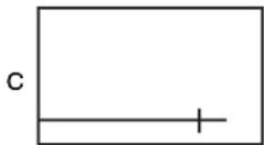
| 1 | 1 | Monitor (see C) |
| 1.1 | 1 | Monitor |
| 1.2 | 1 | Mounting plate + 4 sheet metal screws 4.2 x 15 mm |
| 1.3 | 1 | Connecting lead of connection box to the monitor, approx. 5 m |
| 1.4 | 1 | Connection box + 4 sheet metal screws 4.2 x 15 mm |
| 1.5 | 1 | Connection cable set, two-core |
| 1.6 | 1 | IR remote control |
| 1.7 | 1 | 2 batteries of type AAA |
Subject to technical changes!
Accessories for RMM series
The following articles are available as supplementation to the RMM series:
Designation
wireless infrared headphone
FM modulator for to feed the audio signal into
the audio system of the vehicle. You will need a Y-RCA cable
Camera RV-24, RV-27 via switch box RV-SWITCH-600
Article No.
HS-10
FM-MOD-10
RV-24/RV-27
RV-SWITCH-600
Subject to technical changes and to availability of delivery!
Monitor
Operating elements
Contactor/circuit breaker ambient lightning (see D 1.1)
ambient light (see D 1.2)
push-button to open the monitor (see D 1.3)
infrared-reception window (see D 1.4)
VOL> (see D 1.5)
Button to decrease the volume or function selection/setting in the sub-menu
e.g.brightness, mirror function.
MODE (see D 1.6)
Button to select the function (see also section "Remote control")
VOL< (see D 1.7)
Button to increase the volume or function selection/setting in the sub-menu e.g.
brightness, mirror function.
POWER (see D 1.8)
Contactor/circuit breaker
Terminal block on the upper side of the housing (see D 2)
- CONTROLLER (see D 2.1) Connect the supplied connecting cable from the connection box to the monitor.
- FM(IR) not allocated (see D 2.2).
- FM(IR) not allocated (see D 2.3).
Grey terminals (Dome Light) for the integrated ambient light (see D 2.4). - IR infrared transmitter (headphone) (see D 2.5).
Connection box
At the front:
- TO MONITOR, plug in the socket of the connecting cable to the monitor (see E 1).
Plug in the socket until it audibly engages. - INPUT VIDEO 1 and 2, 2 sockets (RCA) video input 1 and 2 (see E 2).
- Socket supply line, 2-pole socket (see E 3).
The supply line consists of 2 branch lines:
red = 12V - .15V
black = earth
At the rear:
- INPUT AUDIO 1 and 2, 4 sockets (RCA) audio input 1 and 2, stereo (see E 4).
Remote control
Operating elements
POWER, Contactor/circuit breaker (see F 1.1).
Contactor/circuit breaker of the monitor has no function (see F 1.2).
no function (see F 1.3).
If the remote control does not work, press once the MONITORkey
(see F 1.3) and continue then as usual.
VOL UP/DOWN, Volume control, 2 buttons for loud or soft (see F 1.4).
PICTURE (see F 1.5), Button for the image- and function setting (same function as key MODE at the monitor, see D 1.6).
Calls up the menu as follows:
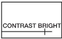
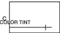
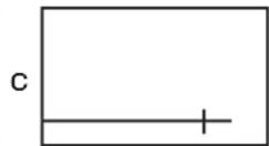
Press the key PICTURE (see F 1.5) on the remote control or MODE (see D 1.6) on the monitor. Graphics appear for the function setting.
Change the values of following graphics with the keys VOL UP/DOWN
(see F 1.4) (see also representation of the screen graphics on the next page)
Contrast (CONTRAST) k Brightness (BRIGHTNESS) k Color (COLOR) k Color value (TINT)
(only with NTSC-video format) k blue screen with missing video signal, On/Off (BLUE
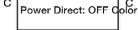
SCREEN) k Automatic switching-on as soon as voltage supply is present, On/Off
(POWER DIRECT) k Video format PAL/NTSC (COLOR SYSTEM)
k normal-/mirror image (MIRROR MODE).
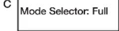
k Image format selection (MODE SELECTOR) (see F 1.5 and D 1.6):
1FULL = 16:9
2 NORMAL = 4:3
3 CINEMA = 16:9 enlarged
4 WIDE = 16:9 reduced in size
MUTE switches off the loudspeaker (see F 1.6).
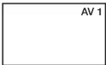
AV is used for switching the video inputs (see F 1.7).
SET direct selection of the image formats (see F 1.8).
Battery change
Push down the cover of the battery compartment (see F 2).
Insert the batteries (2 x 1.5 V, type AAA). Take care that there is correct polarity (see F 3).
Close the compartment again (see F 4).
Remote control
1) Screen graphics (menu) (see F 1.5 or D 1.6)
C
BLUE SCREEN: OFF

C
Mirror Mode: normal
2) AV 1/AV 2 (see F 1.7)

Installation of the monitor
General installation instructions!
Please observe the following points before attaching the monitor:
- Locate monitor first of all on a trial basis.
- The assembly location should be even.
- Check before the final assembly whether the necessary free space is available, also above the assembly place chosen for the attachment of discs and nuts.
- Consider the weight of the monitor. Are reinforcements (larger washers or plates) necessary?
- Is the installation of the wiring harness and connecting cable to the monitor possible?
- Pay attention when locating the monitor that this is not assembled within the radius of an AIRBAG. Otherwise there is danger of injury when it is activated. Do not assemble the monitor within the head impact range.
Installation of the monitor

- Carry out a function test before the assembly.
If an interior light should be installed in the vehicle at a suitable place e.g. between driver- and front seat passenger, the ceiling monitor can be installed at this place. Check that connecting cable has sufficient length from the place of assembly to the connectionbox.

Test whether the monitor can be opened (see H 1.5).

Caution! The ambient light must be without power in order to avoid short-circuits of the monitor during the installation. Remove the ambient light (see H 1.1). Install the mounting plate (see H 1.2). Lay the connecting cable from the monitor to the intended installation place of the connection box. Connect the service line of the original ambient light to the connections of the monitor (there is no need to take into account a polarity) (see H 1.3). Plug the connecting cable into the socket (see H 1.6).
The safety regulations must be absolutely observed.
Installation of the connection box
The assembly place must be protected against humidity. An assembly under the dashboard is recommendable due to the compact design.
The box can be fastened with the supplied sheet-metal screws or self-adhesive Velcro tape (not included in the scope of delivery).
Observe the safety- and installation instructions!
The voltage supply should be provided via a switched voltage source e.g. group 15.
The system has also a certain power consumption when it is switched off
(IRreception active), which can discharge the vehicle battery over a longer period of time.
The connection box provides inputs for 2 video sources (see I 2). This can be a DVD player (WAECO Art.-No. DVD-PL-10), a camera etc. Plug the RCA cable of the video sources into the sockets VIDEO/AUDIO (see I 2). A mono-audio signal is produced when using only one audio input.
Operation of the monitor
The monitor switches on automatically after complete connection with adjacent voltage supply (POWER DIRECT = ON) or you can switch on the device via the remote control (key POWER) (see F 1.1).
If a video source is connected and operated, the image appears and the audio signal is transmitted via the IR-headphone accessory HS-10 (see G 1) or via the car radio (when using the FM-MOD-10).
Activate the key AV (see F 1.7) when changing the video channel on the remote control. If you want to modify settings, it can be done via the keys MODE and VOL at the monitor (see D 1.5/1.6/1.7) or the remote control (see F 1.5/1.4).
The monitor can be turned to both sides and likewise to the rear by approx. 15^ (see G 1 and 2).
Use of the headphone HS-10
The monitors RV-RMM-70 and 104 are equipped with an IR-transmitter. It enables the use of the wireless IR-headphone HS-10 (please refer for more detailed information to the instructions). When using the monitor, you should stay in the range of approx. 120^ horizontally and 60^ vertically in front of it (see G). A trouble-free tone reception can be ensured then.
Failures
Flickering of the picture
The voltage supply has dropped below 12 V. Charge your vehicle battery. A connecting lead as short as possible must be provided from the voltage source to the connection box.
Running of picture
The adjusted video format (COLOR SYSTEM) does not match the video source. Change the format e.g. from NTSC to PAL.
Technical data
Dimensions (WxHxD): 210 × 230 × 40 mm (RV-RMM-70)
Dimensions (WxHxD): 285 × 310 × 40 mm (RV-RMM-104)
Operating voltage: 12 V DC, max. 15 V
Current consumption: max. 16 watts incl. ambient light (RV-RMM-70)
18 watts incl. ambient light (RV-RMM-104)
Size of picture: 7", 17.7 cm diagonal (RV-RMM-70)
Size of picture: 10.4^ 26.4 cm diagonal (RV-RMM-104)
Pixels: 337.000", 17.7 cm diagonal (RV-RMM-70)
Pixels: 480.000", 17.7 cm diagonal (RV-RMM-104)
Video standard: NTSC/PAL
Operating temperature: 0^ to +60^
Weight: approx. 1.5kg (RV-RMM-70)
Weight: approx. 2.5kg (RV-RMM-104)
We reserve the right to make changes serving technical progress.
Please keep these operating instructions in a safe place, hand them over to the buyer together with the unit if you sell the unit.
If you have any further questions about RV-RMM-70 or RV-RMM-104, please contact:
WAECO UK Ltd.
UK-Broadmayne · Dorset DT2 8LY
Unit G1 · Roman Hill · Business Park
phone: +44-13 05/85 40 00 · fax: +44-13 05/85 42 88
www.waeco.com
phone: +34-93/7 50 22 77
fax: +34-93/7 50 05 52
www.waeco.com
Power Direct: OFF Color
1
system: PAL
C
Mode Selector: Full
C
Mirror Mode: Normal
Interrupttore on/off
C Power Direct: OFF Color
System: PAL
C Mode Selector: Full
C
Mirror Mode: nomaal
2) AV 1/AV 2 (zie F 1.7)
Montage van de monitor
Algemene montagevoorschriften!

- List of contents
- Title Page
- Information on using the installation instructions
- Warning! Safety note:
- Caution! Safety note:
- WAECO UK Ltd.
- General safety and installation instructions
- Depending on the vehicle's equipment, the following data may need to be reprogrammed:
- Warning! Parts of the LCD ceiling monitor
- Tools required
- The following are required for the installation:
- The following are required for the electrical connection and the check:
- Scope of delivery
- Accessories for RMM series
- Designation
- Article No.
- Monitor
- Operating elements
- Connection box
- At the front:
- At the rear:
- Remote control
- Battery change
- Installation of the monitor
- General installation instructions!
- Installation of the connection box
- Operation of the monitor
- Use of the headphone HS-10
- Failures
- Flickering of the picture
- Running of picture
- Technical data
- Montage van de monitor
- Algemene montagevoorschriften!
Brand : WAECO
Model : Mobitronic RVRMM104
Category : LCD Screen