NavGate HeadUp SPXHUD01 - GPS Navigation System PIONEER - Free user manual and instructions
Find the device manual for free NavGate HeadUp SPXHUD01 PIONEER in PDF.
| Product Type | GPS navigation system with head-up display (HUD) |
| Brand | Pioneer |
| Model | NavGate HeadUp SPXHUD01 |
| Dimensions (mounting bracket) | Adjustable thickness from 15 mm to 33 mm; minimum height 40 mm; minimum width 185 mm |
| Weight | Approximately 200 g (main unit) |
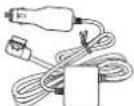
| Power supply | 12 V DC via cigarette lighter plug; built-in lithium-ion battery for remote control |
| Power consumption | Fuse of specified capacity (check on cable) |
| Main functions | Projection of images onto windshield, GPS navigation via smartphone (iPhone/Android), display modes (AR, list, junction, overview, clock), angle adjustments, brightness, geometric correction, white balance |
| Connectivity | USB (cable provided) for connection to smartphone; power cable with cigarette lighter |
| Smartphone compatibility | iPhone (compatible models) and Android devices; dedicated NavGate navigation app |
| Included accessories | Main unit, remote control (with battery), power cable, USB cable, thickness adjustment plates, screws, hex key, anti-drop strap, protective film |
| Maintenance and cleaning | Clean with a soft cloth; do not use solvents; remove protective film after installation; close display and multiplexer when exposed to sun |
| Safety | Installation on sun visor only with anti-drop strap; do not use while driving; respect traffic regulations; do not obstruct driver's view |
| Spare parts and repairability | Spare parts available from Pioneer; repair by authorized center; do not disassemble the device yourself |
| Operating temperature | Temperature range not specified, avoid extreme temperatures (device automatically reduces brightness outside range) |
| General information | Manual available in several languages; software update via SD card; usage data recorded for improvement |
Frequently Asked Questions - NavGate HeadUp SPXHUD01 PIONEER
User questions about NavGate HeadUp SPXHUD01 PIONEER
0 question about this device. Answer the ones you know or ask your own.
Ask a new question about this device
Download the instructions for your GPS Navigation System in PDF format for free! Find your manual NavGate HeadUp SPXHUD01 - PIONEER and take your electronic device back in hand. On this page are published all the documents necessary for the use of your device. NavGate HeadUp SPXHUD01 by PIONEER.
USER MANUAL NavGate HeadUp SPXHUD01 PIONEER
For the operation manual 2
Information for users on collection and
disposalofoldequipmentandoused
batteries2
Connectionandinstallation3
Aboutthisunit4
Precautionsforbattery4
If you experience problems 5
02 Important safety information
Toavo dbalteryexhaustion6
lithescreenishardtosee6
Precautionsforoperationathign/low
temperatures6
NotesonmicroSDmemorycards6
NotesoniPhone6
NotesonAndriodevces6
Copyrights7
Softwareupdates7
Vis tourwebsite7
Savedcustomerdata7
Notesonthisunit7
03 Partssupplied
04 Beforeconnection
Precautionsforconnection8
Connecting the power cab e8
Preventingnoise8
05 Precautionsforinstallation
Beforeinstallingandsecuringunit9
Whensecuringtheunit9
06 Connections
Connectiondiagram9
Settinglhesizeofthecigarettep ug10
Whenreplacingcigarettepugfuse10
07 Installationposition
Precautionsforinstallingunit10
Specfiedinstallationposition10
08 Preparationforinstallingtheunit
When replacing the unsatisf thickness
adjustmentplate11
09 InstallingMainUnit
Afterinstallation16
Connecting the powerable to the cigarette
socket16
10 SettingyouriPhoneorAndroiddevice
ConnectingyouriPhoneorAndroiddevice
totheunit17
Installingthenavigationapplication17
Startingthenavigationapplication17
⑪ Displaymodes
12 Whenyoufinishwithinstallationand connection
Adjustingthedisplaysettings18
-Position18
-Zoom18
-Rotation 19
-AspectRatio19
-GeometricCorrection19
-WhiteBalance19
13 Beforedriving
Configuringtheunitfunction
settings20
Adjusting the angle of the combiner 20
Whengeltinginandoulofthe
vehicle20
Correctcombinerposition20
Adjusting the display brightness20
Precautions
Important
• Foryoursafety, besuretoask your dealertoinstalltheunittoyourvehicle, wirethecables, orchangeitsinstallation location.
Installation, wiring, and disinstallation requires special skills and experience. Incorrect installation, wiring, or disinstallation of the unit, using parts other than those specified by the manufacturer may cause an accident, injury, or malfunction. In this case, Pioneer accepts no responsibility.
•Todealers
When you are finished with the installation andwiring.proceedtosetuptheconnen
t o w th then a v g a t o n u n i t a n d a d j u s t
thedisplaysettings,etc.
When you are finished with all of the work.
handoverthismanualtoyourcustomer.
ThankyouforpurchasingthisPIONEER product
Toensure proper use, pleasereadthrough this manualbeforeusing this product. It is especially important that your read and observe WARN-
INGsano CAUTIONsinthismanual.Please keep themanualinasafeandaccessibleplacefor futureretence.
Fortheoperationmanual
This manual describes how to install and setup this unit. Operation of this unit is explained in these separate manual for the unit.
For details on the functions and operation of this unit, visit us at the following site:
http://www.pioneer.eu/navgatenud

Informationforuserson collectionanddisposalofold equipmentandusedbatteries
(Symbolforequipment)

(Symbolexamplesforbatteries)


Pb

Engb
Precautions
Thesesymbolsontheproducts, packaging, and/or accompanying documents meant that usedelectrical and electronic products and batteries should not be mixed with general household waste.
Forpropertreatment, recovery and recycling of old products and used batteries, pleasetakethem to applicable collection points in accordance with your national legislation.
By disposing of these products and batteries correctly, you will help to save valuable resources and prevent any potential negative effects on human health and the environment which could otherwise arise from inappropriate waste handling.
Formoreinformationaboutcollectionandrecy- clingofoloproductsandbatteries,pleasecon- lactyourlocalmunicipalityyourwastedisposal serviceorthepointofsalewhereyoupurchased theitems.
ThesesymbolsareonlyvalidintheEuropeanUnion.
Forcountriesoutsidethe EuropeanUnion:
If you wish to discard these items, please contact your local author or dealer and ask for the correct method of disposal.
Connectionandinstallation

WARNING
- Use this unit with a 2-volt battery and negative earthing only. Don't use the unit for a 24-volt vehicle. There is a risk of fireorma function.
- Neverinstalltheunitandwiretnecab esto placeswhereitwillimpairtheperformance ofanairbag.
When installing the unit to a vehicle equipped with airbags, ask the vehicle manufacturer for precautions for the installation work. There is a risk of incorrect deployment of airbags, resulting in a fatal accident.
- Never install the un places where it will obstruct the driver's vision, interfered driving or caused danger to the passengers. There is an skof traffic accident and injury.
- Never cut the insulation of the power cable of this unit to raise the power with other devices. Exceeding the current capacity of the power cable may result in a fire, electric shock, or malfunction.
- Never use the bolts and nuts of safety related parts such as the steering, brakes systems and tank. Using these may cause abrake failure, fire, or traffic accident.
- Donotinstalltheunittoasunvisorwhose shapeisnotsupportedbytheunit, Installingtheunittoasunvisorwhose shapeisnotsupportedbytheunitmay causeanaccidenlormalfunction.
- Donotinstalltheunitloadefectivesun visor.
Checkiftherearenodefectionthesunvisor beforeinstallation.Installationtcadefective sunvisormaycausctnounittotfall,resulting inanaccidentorma function.
- Donolleavelheunlinaplacesubjectlodirochtsunlight.
Donotremovelhecombinerprotection sheelbeforetheinstallationiscompleted. Thecombinemayconcentratlightintoan intensebeam,causingsmokcortire.
- Foryoursafely, ask your dealer to install the unit tanowirethecaclos, or changethein-stallation location.
Precautions
Installation, wiring, and dis installation of the unit requires special skills and experience. In-correct installation, wiring, or dis installation of the unit may cause serious damage to the vehicle.
- Donctworkinaplacesubjecttodirectsunlight. Doingsomaycauseaburninjuryorblindness.
- Disconnect the negativeterminal of the battery before installation. Short circuiting the posit ve and negativeterminals may cause electric shock or injury.
- Checktnelocationofthepipes,tank.electricalwiring,etc.before installation. Wheninstallingtheunitbydrillingholein thevehiclebody,becarefulnctointertere withorcontactthepipes,tank.electricalwiring,etc.Furthermore,protecttheprocessed partsfromstingorthepenetrationof water.
- Use the supplied parts and secure them firmly. Use of part other than the supplied ones may cause damage to other parts in the unit or may not be able to firmly secure the unit, if the unit comes loose, it may interfere with driving, causing an accident and injury.
• Install the supplied parts specified. If the supplied parts are not installed as specified, the parts may come loose and drop off resulting in an accident or malfunction.
- Use the supplied cables and connect them securely. Use the supplied cables and connect them as specified. Use cable so other than the supplied ones may cause a normal malfunction.
- Followtheinstructionsinthismanualtoconnectandinstalltheunit. Failure to follow the instructions in this manual to connect and install the unit may cause a firecraccident.
- Secure the unit to sun is on with a fall prevention cell. Failure to do osomay cause the unit to fall, causing an accident and injury.
• Insulate an uninsulated paro thecable with tape, etc. A short-circuit may cause a fire, electric shock, or malfunction.
• Wire the cableless that they donot get caught on the vehicle body screws or moving parts such as a seat rail. Adisconnection or short-circuit may cause a fire, electric shock, or malfunction.
• Wire and secure the cable less so that they do not interfere with driving. Failure to do osomay cause the cable stoget tangled around the steering wheel, gear stick, brake pedal, etc., causing an accident.
- When you are finished with the installation and wiring, check that the electric equipment works normally as it did before installing the unit. Using the unit whilst there electric equipment does not work normally may cause a fire, electric shock, or traffic accident.
- Storesmallpartssuchasscrewsoutofthe reachofsmallchildren. Shouldthepartsbeswalowed,consulta doctorimmediately.

CAUTION
- Nevercuttacablepartwayalongit. Ifatuseisconnectedofnecable,thepro lectioncircuitwillnotwork,whichmay causeafire.
- Whenconnecting cables, makes sure that the cablesdonolcomeintocontactwithrot areasofthevehiclebody. There is a risk of air on electrocshock.
- Donotwirecablesusingexlens oncords. Doingsomaycause,hecablelooverheal, resultinginatireorelectricshock.
Section
Precautions
- Donot install the unit in place subject to conditions such as rain, water, condensation, dust, and oil smoke.
- Deingsomay causes smoke, fire, or malfunction.
- When wiring, donotallow the cablesto come into contact with metalparts. Allowing cablesto come into contact with metalparts may damage the cab es, causing afire, electric shock, or malfunction.
Aboutthisunit

WARNING
- Donotoperatethemenuswhistdriving.It will divert your attention on away from the safe operaton of your vehicle and may cause a serious traffic accident. Always observe traffic conditions and pedestrians ensure that you drives safely.
- Donotstareatthedisplayedimagewhilst driving. Failuretokeepyoureyesontheroadahead maycauseanaccident.
- Donoloperatethesunvisorwhilstdrving. DoingsomaycauseaseroustratticaccidenL.Parkyourvehicleinasafelocationand applythehandbrakebeforeoperatingthe survivor.
- Donot insert your hand for fingers orator eignooject intoamediaslot. Doingsomaycausaninjury, electric shock fire or malfunction.
- Donotallow this unillocome in contact with liquids. Doings may cause smoke, fire, or electric shock. Special attention is required in the case of families with children.
• If liquid foreign matters should get inside this unit turn off the power immediately and consult your dealer therenearest authorised PIONEER Service Station. Don't use the unit in this condition because doing so may result inf re, electric shock, prother failure.
- Donotleavetheremotecontrol,etc.lying around.
When stoppingthevehicleorturningabend,theremotecontrol,etc.mayclltowardyour testandgetundertheprakepedal,interferingwithdrivingandcausinganaccident.
• Donotaffixf Imorasealtcthecombiner. Doingsomayblockthetfieldotvision, causinganaccident.
- Donotusetheunitifthere sanabnormality
ormalfunct onsuchasimagesnotbeing
abletobedisplayed.
Thereisariskofanunexpectedaccident,
fire,orelectricshock.
- Donotallowchildrenchangeontheunitor applyforcetol.
Doingsomaycauseaninjury,vehicledeformation,ormaltfunction.
- When you hear thunder don't touch the unit.
There is a risk of electric shock caused by lightning.
- Dorodisassembleormodify.theunit. Thereisariskotanaccident.fire.orlectric shock.
• Always dobey the actual traffic regulators. Thou t contains a traffic regulation, but some of the data may differ from the actual traffic regulations, do such changes the traffic regulations. Even when using a route maps or to guidance the navigation always dobey the actual traffic regulation on sand actual traffic signs when operating available. Failure to dosomay causanacc dentoresult Navio adonof herad traffic laws.
Precautions
- This unit disables operation of the unit whilst the vehic eisin motion. Parkthevehic eina safeplace and app yahandbrake before operating the menus of this unit.
- Replacethefusewithanewoneofthespecifiedcapacity(ampere). Usingafuseexceedingthespecifiedcapacitymaycausefireormalfunction.
- Before using the unital night time or a dark places such as inatunnel, adjust the brightness of the unit properly so that it will not interfere with driving. Failure to do so may cause an accident.

CAUTION
- Donotusetheunitforanyourposoother thanuseinavericle. Doingsomaycausesmoke,fire,electric shock,orinjury.
- Before driving, adjust the combiner angle and display brightness, and check is screws on the unit are not loose to prevent them from interfering with driving.
Failureodosomaycauseanaccident. - When operating the sunvisor buttons, whilst driving, pays sufficient attention to your driving
Failure todos may cause an accident.
- When getting in and out of your vehicle, be careful not to bang your head on the unit. Failure to do so may cause an injury.
- Recarstulnottolethandsorfngersget caughtwhenyouareclosingthecombiner oradjustingtheangle. Failuretodosomaycausean injury.
Precautionsforbattery

WARNING
- Keep the battery out of these achofs small children to prevent an accident from a hemorrhage.
Should the battery beswallowed, consult a doctor immediately.
- Insta the battery according to the pecolarity (positive and negative) specified in this manual. If the battery pecolarity is not correct, there is a risk of an injury or contamination of the environment due to the explosion or the battery or leakage of the battery fluid.
- If the battery leakage occurs and the battery fluid gets on your skin or clothes, wash it off with clean water. If the battery fluid gets into an eye, wash it out with clean water and consult a doctor immediately.

CAUTION
- Donotshort-circuit,disassemble,orheathe battery,orplacetinfirecrwater. Explosionofthebatteryorleakageofthebatteryfluidmaycauseafireorinjury.
- Donolchargeadrybattery. Explosionofthebatterymaycausean injury.
- Donotuseabatteryotherthanthespecified one. Explosionofthebatteryorleakageofthebatterylfluidmaycaesaninjurycorcontaminationoftheenvironment.
- Replaceausedbatteryimmediatelywith a newone. Leakageofthebatteryfluidmaycausecon taminationoftheenvironment.
- Donotstoretheremotecontrolinnighttemperatures, highhumidity, indirect sunlight. Failurelodosomaycauseremotecontrol deformation, explosionofthebattery, or leakageofthebatteryful.
Precautions
Ifyouexperienceproblems

WARNING
If you notice smoke, astrangenoiseorsmell, or any other abnormalities from the unit, turn off the power rimmed ately and consul your dealer orthencarostauthorised PIONFERService Station.
Using this unit in this condition may cause an accident, fire, or electric shock.
Important safety information
• The unit does not work standalone. Connect the unit with iPhone or Android device on which an navigation application is installed before using it.
Reachesafelyprecautionsdescribedinthe instructionmanualoftheproductthatisto beconnectedtothisunit.
- Dancotoperatethisunitwhilstoriving. It will diver your attention away from the safe operation of your vehicle and may cause passenger traffic accident. Always observe traffic conditions and doiestrianstensure that you drive safely. Parkyourvehic einasaflocation and apply the handbrakes before operating this unit.
- Donctoperatethesunv sorwhilstdrving. Doingsomaycauseaserioustratficaccident. Parkyourvehicleinasafelocationand applythehandbrakebeforeoperating the sunvisor.
- DonctoperateaniPhoneorAndroiddevice whilstdriving.ParkyourvehicleinasafelocationandapplythehandbrakebeforesettingaroutetoyourdestinationonaniPhoneorAndroiddevice.
- Allfunctionsavailableintheunildonotin anywayguarantoothatyoursurroundings aresafe.Whendrving,besurelocheckthat yoursurrounding ssaefwithyouowneyes.
• The route information and voice guidance provided by navigation application are for reference purposes only. Always obey the local traffic regulations and actual traffic sign when operating vehicle. Failure to comycouloresullar ovation of real traffic laws and cause serious traffic accident to occur. In addition, information laying the distance vehicle front of flow vehicle, speciosigns and redlightcamer aspiayed by this unitist or reference purposes only. Obeyactualtraffic signs and driving conditions.
- This unit is equipped with an interlock system that detects when the vehicle is moving and disables operation of the unit whilst the vehicle is in motion. Park the vehicle is a safe place and apolyahandbrake before operating this unit.
- If you experience redness or discomfort whilst using this unit, stop use immediately and take along break to recover properly. Continue use of the tunders such circumstances may have adverse effect on your physical condition.
- If you are short-sighted or far-sighted, have astigmatismordiffering visual acuities between your left and right eyes, wear glasses, etc. to properly correct visual acuity before using this unit.
- Imagesdisplayedonthescreenmaybedis-tortedmomentarilywhenthedisplayed imageswitches.Thisisnotamalfunction
- Imageswillnotbeisplayedonthescreenif theGPSreceptionislost.
- Images displayed on the screen may be distorted if an Phone or Andro devices under heavy load.
- Positioning accuracy depends on the performance of GPSonaniPhoneorAndroid device connected to this unit.
- Thedirectionallongwhichvehicleistravellingmaynotbedisplayedcorrectlyifthe GPSaccuracyislow.
- FirmlysecureaniPhoneorAndroiddevice whilstdriving.DonotletaniPhonceor Androiddev cefallentothefloor,whereil maybecomejammedunderthebrakeoracceleratorpedal.
• Cosethed fuserwhennotusingthe.unit. - When removing the unifrom the sunvisor and storing it, because closed diffuser and combiner. Don't leave the unit places exposed directly sunlight such as dashboard. The diffuser or combiner may concentrate light into an intense beam causing smoke online
Section
02
Important safety information
- Thetaillightofthevehicleinfrontmaybere-flectedonthecombiner.
- Pioneer accepts no responsibility for any fluctuations in the value of appraisal of the vehicle, etc.
Toavoidbatteryexhaustion
- Besuretokeep the vehicleenginer running whilst using this unit. Using this unit with the vehicleenginetumedotic and rain the battery.
Don't allow the vehicleengineto die for longer than necessary whilst parkstomini mize effect on the surrounding environment.
• litheunitdocsnotturnoff(thel. FCindicator onthec garetteclugo thepowercabiere-mairslilywhenthevehicleenginesturned off.disconnectthopowercablefromthecig aretlesocketonthevehicle.Failureletodoso willdrainthevehiclablebattery.
Ifthescreenishardtosee
- This unithasarangeofang esthattheimagesonthescreencanbeclearlyseen. Adjust the angle of the combiner (page20) and thodisplaysettings (page15) when using this unithor the first metoolm is the visibility and a ty of displayed images. You can adjust the display brightness using the Button (page20).
- The display brightness differs depending on the viewing angle. Use the unit at the position where you can clearly seeth displayed image.
Precautionsforoperationat high/lowtemperatures
- If the temperature is too high to allow for the unit to operate properly, the display brightness will be lowered or the projection of images will best operate automatically to protect the unit parts. This sectional function. Wait until the temperature returns to the proper temperature for the unit to operate.
• This unit will not operate properly if the temperature stoch ghorctoclow. Operate the unit within the specified operable temperature range. Fordetails, referto the operation manual.
NotesonmicroSDmemory cards
- This units supports microSDmemorycards and microSDIICmemorycards. These types of storagemedia are collectively referred to as "SDmemorycard" in this guide.
- This unit does not support microSDXC memory cards.
- PioneerdoesnotguaranteetheoperationofallofthetypesofSDmemorycardscompat-blewiththisunit.
- DonatejectanSDmemorycardchange thepositionoftheignitionswitchwhilstthe insertedSDmemorycardisbeingaccessed. ItmaycorruptthedatastoredontheSD memorycard.Pioneeracceptsneliabilityfor anydarmagesansinginsuchcases.
- SDmemorycards haveasetlifespan. Even if an SDmemorycardhasbeenusedproperty, datamaynotbeabietobewrittentoordletedfromtheSDmemorycardcorrectly oncethecarchasreachedtheendofitsusefullife.
Important safety information
SomeSDmemorycardsmaynotecrecognisedbyhlsunileveniftheSDmemorycardscanberecognisedbyacomputer. FormattingtheSDmemorycardsusingadedicatedformattermayreso vetheproblem.SDmemorycardsformattedusingthestandard formattingfunctiononacomputerdonot complywiththeSDstandard.Problemsuch asthathosecardscannolbereacowritten couldoccur.Itisrecommendedthatyouuse adedicatedformatteroavoidsuchproblems.AllothedatastoreconenSDmemorycardwillbeceletedwhenthecards formatted.Backupanyneededatbeforehandasnecessary.Adedicateformatteror SDmemorycardscanbeobtainedfromthe followingsite.
https://www.sdcard.org/home/ (Validaso(June2012)
•PioneercannotguaranteerepairofanSD memorycardwithdefectscausedbytheSD memorycardbeingformattedInsedition. Pioneeracceptsnoliabiltyfordamages, costsacexpensesansiralingfromdatallossor corruptionoccurringduelotheSDmemory cardbeingformatted.Readtheinstruction manualfortheformatterandtollowwhen-structionsgiventoformaltheSDmemory cardlathyouplanipuse acceptingresponsibilitycourseforanyproblemthatmay occur.
NotesoniPhone
- For the Phonemodels and Phonesoftware versions supported by this product, refer to the information on our website.
•TheiPhonemode scompat blewith this unit are collectively referred to as iPhone in this guide. -
Pioneerdoesnotguaranteetheoperationof allofthetypesofiPhenemodelscompatible withthisunit.
-
Pioneeraccepts reliability for any data loss that may occur with use of a iPhone with this unit.
- Donot eaveaniPhoneindirectsunlightfor longperiodsoftime.Itmaycausethe IPhonetomalfunction.
- Donot leaveaniPhoneinhigtemperature.
- For details on the iPhone, refer to the iPhone manuals.
NotesonAndroiddevices
• For the Android device supported by this product, refer to the information on our website.
- Compatibility with all Android devices is not guaranteed.
Certain uses of an Android device may not be labeled, while the following your jurisdiction, so you must be aware if any such restrictions. If doubt about particular function, only perform whilst this could be parked. Note should be used unless it is safe to download driving conditions you are experiencing.
- Pioneeracceptsnolabilityforanydataloss thatmayoccurwithuscofanAndroiddevice withthisunit.
- Donol eavean Android device indirect sunlight for long period soft time may cause the device to function.
- Don't leave an Android device in hightemperatures.
- ForetailsonAndroiddevices, refertothe Androiddevicemanuals.
Important safety information
Copyrights
Copyrightistolhedalaandprogrammes includedwiththisproductarthropropertyofPioneeroroththirdpartieshavegrantedrightsPioneerltheuseofsuchdalaorogrammesundercopyright.Youshallnetcopy, modifyoranalyzeanypartorallothcataorprogrammesofthisproductinaryform.
Softwareupdates
• AnSDmemorycardwithacapacityofat least2GBisrequiredforsavingthesoftware uplatefile.
- AmicroSDmemorycardcontainingthelatestupdatedsoftwareversionwillbeavailable onceayearforcustomersdonotnavelinternaccess. Detailswillbepostedonthewebsite.
Visitourwebsite
Visitusatthefollowingsite:
http://www.pioneer.co.uk
- Registryyourproduct.Wewillkeepthedetailsofyourpurchaseconfiletohalpyourcferlo:hisinformationintheeventofaninsuranceclaimsuchaslossortneft.
• We offer the latest information about PIONEERCORPORATION nonour website.
Savedcustomerdata
- Incaseswhereunitrepairsareneeded,etc., Pioneeracceptsnorresponsibilityforsoftwareupdatesperformedbythecustomer.
- Settings registered to this unit may be altered or deleted automatically by accident, dueto unit malfunction, as part of the repair process, or whilst other procedures are being performed. Retainalist of important content. Poneer accepts sol liability for damages or lost benefits arising from data loss in such cases.
- Pioneerdoesnotprovideaservicetorecover damagedoreraseddata.
Notesonthisunit
The operating history of this unit is recorded for performance improvement purposes. No customer information is obtained during the recording of this history. The recorded information can be shared with other facilities or subcontractors specified by Pioneer thereafter analysis only per permission from the customer is obtained in advance.
- Pioneerhasted and confirmed that projected images can be seen at distance of 3m from the front of the windscreen of the vehicle. However, distances may appear different depending on the driver's seating height and seat position, the ghtandtilt of the vehicle's scelling, and the amount of ambient light.
- Pioneerdoesnotguarantesthattheproduct conformstolheparticularpurposeofaspecificuser.
- Unitspecificationsanddesignsaresubject tochangewilhoutoriornoliceforproduct improvementpurposes. Pioneerdoesnotac- capturevenacknowledgementorrequests forproductmodificationorexchangebaccommodatespecific Customerneedsfor productsthatmatcthespecificationsand designsdescribedherein.
- Thescreenimagesinthismanualmaydiffer fromthosefortheactualproduct.
Important safety information
- Thescreendisplaydesignissubjectto changewithoutpriomoticeforproductim-provementpurposes.
Section
- Thescreendisplaydesignissubjectto changewithoutpriomoticeforproductim-provementpurposes.
Partssupplied
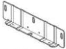
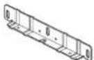
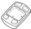
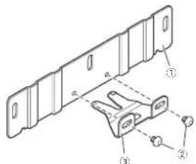
Head-updisplayunit:
Mainunitx
Mountingbracket
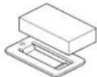
Survivorthicknessad|c.s.mont plate(srge)x1
Sunvisorthickness adjustment plate(sma lix1

Mountrose sawb

Hexagona soan hex1
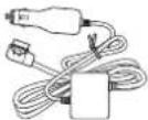
Powercablex1
Sunv sorcushionx1

Double-sidedlapex1
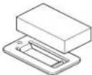
HUDremotecontrol:
Mainunit
(Aithiumion battery is preinstalled. Remove the insulationsheet before using the unit.)
Beforeconnection
Precautionsforconnection

CAUTION
- DonottakeaccessorypowerfromtheCAN BusinInterface etc.Besure,connectlthe accessorypowersupplyofthevehicle.
• Installthesupplicopartsaspecif ed. Useofpartsotherthanthesuppliedones maycauseama function.
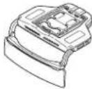
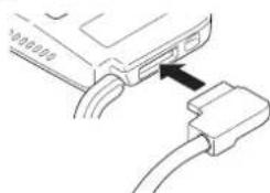
Connectingthepowercable
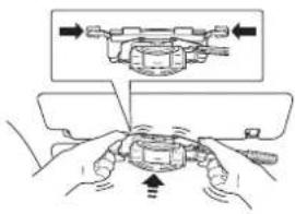
- Firmlyconnectropowercablebyinserting it into the power connector on the unit. If the connector cannot be inserted, the orientation may not be correct. Check the orientation of the connector Donutuse force to push it. Doings may cause an malfunction.
natural_image
Diagram of a USB cable connector with an arrow pointing to the cable (no text or symbols present)Preventingnoise
- Topreventnoise placethefollowingitemsas farfromaniPhone,anAndro ddevice,and othercablesandcordsaspossible.
—Fimaeria andaerialcable
—FM/AMaerialancitsaerialcable
—GPSaerialanditsaerialcable
—Beaconreceiveranditsaerialcable
—Powercable
Placetheaerialsasfarfromeachotheras possible.
- Donottietheaerialstogether,stackthem,or crossthemovereachother.
Noisereceived by the aerial and aerial cable reduces reception sensitivity.
Precautionsforinstallation

WARNING
- Secure the unit to disunvisor with a fall prevention bolt. Failure to do so may cause the unit to fall, causing an accident and injury.
- When installing the unit to vehicle equipped with airbags, never install the unit on the cover of fan airbag or nplace where it will interfere with the deployment fan air bag. Doings may prevent the airbag from deploying normally, or the deployed airbag may hit the unit, causing an accident and injury.
- Donotworkinaplaces,bjectocirectsunlight,Doingsomaycauseaburninjury. Furthermore,there isariskofblindness caused byexposureosunlight reflected from thecombiner.Ifthecombiner exposed to direct sunlight,closethecombiner.
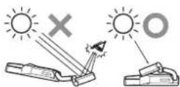
- Donotleavetheunitnaplacesubject:odiroctsunlight. Donotremovethecombinerprotection sheetbeforetheinstallationiscompleted. Thecomb-normayconcentrateightintoan intensebeam,causingsmokeonfre.
- Never install the unit to a vehicle equipped with as unroofortoconvertible. Sunlight may be affected by the combiner and concentrated into an intense beam.
- Donotusethesunvisoronthesidewindow with this unit mounted on it.

CAUTION
- When installing the un-tloa vehicle equipped with airbags, ask the vehicle manufacturer for precautions for the installation work. There is a risk of incorrect deployment of airbags resulting in fatal accident.
- Asunvisonightandotheroptionalaccessoriesaroundthesunvsorsuchasacardholderandsunvisomirromaynotbeacletobeusedafterinstallingtheunit.Checktheaccessoriesinthevehiclebeforehand.
• The installation of the unit may leavemarks on the surface of the survivor. - This suritisnotsupposedtoeinstalledon thepassengerseat.
- Parts,dust,etc.mayfallcnyouwhilstyou areinstallingtheunit.Topreventdust,etc.fromgettingltoaneye.donotlookupat.theunitfromdirectlycelowwhilstinstallingtheunit.
• Thediffuserandcombineroftheunitaredelicateparts.Donottouchthemwithbare handsorcauseatooltocomeintocontact withthemwhilstinstallingtheunit.
Beforeinstallingand securingunit
Firstconnecttheunittemporarilycheck that theunitworksnormally, and then install the unit. If theunitdoesnotworknormally, check if theconnectioniscorrect.
Whensecuringtheunit
- Recommended tightening torque for securing the unit with screws from 0.36N·mto 0.59N·m.
- Before applying the double-sided tape to the connection box of the powerable thoroughly peptany dirt from the surface to which the double-sided tape is be applied.
Connections
Connectiondiagram
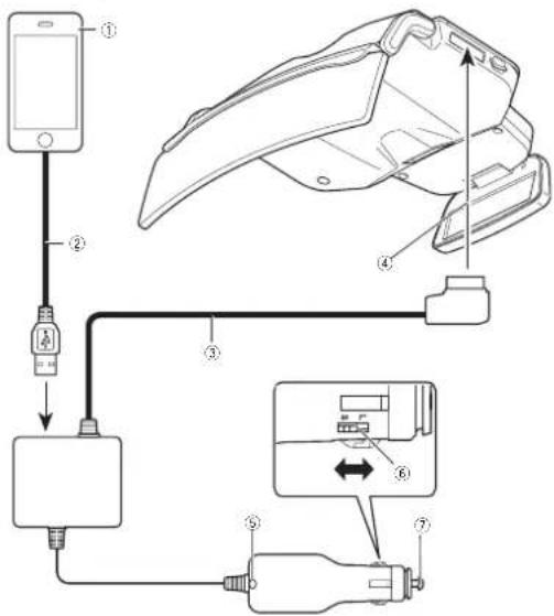
①iPhoneorAndroiddevice
②USBcable
③Powercable
④Tothepowerconnector
⑤LEDindicator
⑥Plugsizeswitch
⑦Tothecigarettesocket
ForiPhoneusers
- Use the cable (2) supplicowiththeiPhone. Donotleavethacableinthevehicle. The cablesupplicowiththeiPhone snotdesignedforuseinavehicle.
ForAndroiddeviceusers
- UseaUSB microUSB data communication cable(2) of 1 morless. A chargeable cannot be used.
Notes
• The LEDind catoronthecigarettepluglights when the powerison, and turnsoffwhen the unitsturnedoff.
If the LEDindicatordoes notumoffwhen the vehicleengineisturnedoff, disconnect the powercablefromthe cigarettesocketon the vehicle. Failurecosowill drainthe vehiclebacteria.
- FordetailsonconnectinganiPhoneor Androiddevice,refertoSettingyouriPhone orAndroiddeviceonpage17.
Settingthesizeofthe cigaretteplug
Setthecigaretteplugs zetoL(large)orS (small)according to the size of the cigarette socket on the vehicle.
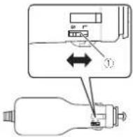
①Plugsizeswitch
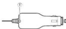
Whenreplacingcigarette plugfuse
1Turntheplugcounterclockwisetoloosen it.
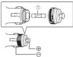
①Fuse(3A)
2Replacethefusewithanewonewith thesamecapacity.
Installationposition
Precautionsforinstallingunit

WARNING
• Use the supplied screws and install the unit as specified. Use of screw other than the supplied ones may cause damage to the unit.
- Securethe unittothesurvisortirmlyusing thesuppliedscrews. Failurelodosomay causetrounittotallduringdriving,hittinga headandcausingan injury.
- Read this manual fully and carefully, and install the unit correct ytoabioebythesafety standards.
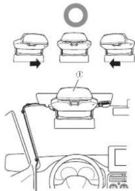
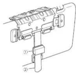
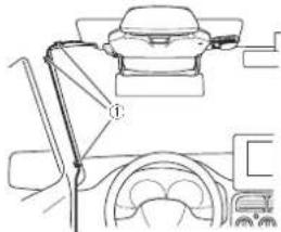
Specifiedinstallationposition

CAUTION
Installthoun tinthospecifiedinstallationpositionloprovide.hedriverwithasafeifedvisionandensure.heunilcanperforms requiredfunctions.installingthoun.tinapositionothernantrespecifiedonemaynoormestthesafelystandalsforrcdruckingvehicles,andthevehiclomaytallasafetyinspection,for example,dueloamaintenanceerror.
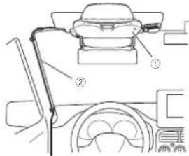
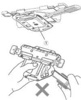
①Mainunit
②Powercable
Preparationforinstallingtheunit

CAUTION
Dorolinstalltheunitioarunstableordefective surveyor.Doingsomaycausetheunititofall,ro- sultinginanaccidentormalfunction.
1Checkthesunvisor.
Checkthethicknessofthesunvisortoinstall treun tlo.
The unit can be installed to surveillance that meet the following specifications.
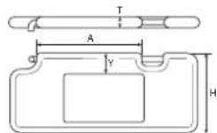
T:Thickness15mm to 33mm
H:Height140mm to240mm
| A:Distancebetweensupportpoints | 185mmormore |
| Y:Distanoctothemirror,etc. | 45mmormore(recommended) |
2Checkthesunvisorthicknessadjustment platetobeused.
The sizeofthesunvisorthickness adjustment plate to be mounted to the mounting bracket difference depending on the sunvisorthickness.
Trisunitcomes with the unvisorth ckness adjustment plate (medium) premounted.
Use the sunvisorth ckness adjustment of the zematching the sunvisorth ckness.
| SunVisorThick-ness | Sunvisorthicknessadjustmentplate |
| 15mmto20mm | Sunvisorthicknessadjustmentplate(small) |
| 20mmto26.5mm | Sunvisorthicknessadjustmentplate(cmodium) |
| 26.0mmto33mm | Sunvisorthicknessadjustmentplate(large) |
Whenreplacingthesunvisor thicknessadjustmentplate
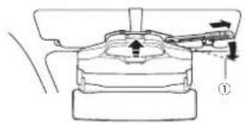
1 Pull the HUDlock lever, and slide it to the lock-release position.
①Lock-releaseposition ②HUDlocklever
2Removetheeightscrewsincludinglongitudinaldirectionadjustmentscrews(shown intheillustration)onthemountingbracket, andthenremovethesunvisorthicknessadjustmentplate(medium).
Ithelongitudinal direction adjustments screws are removed, the longitudinal direction adjustment plate is removed from the unviscrt thickness adjustment plate.
Preparationforinstallingtheunit
①Sunvisorthicknessadjustmentplate
② Longitudinal direction adjustment screws
③ Longitudinal direction adjustment plate
3Attachthelongitudinaldirectionadjustmentplatetothesunvisorthicknessadjustmentplatetobeused.
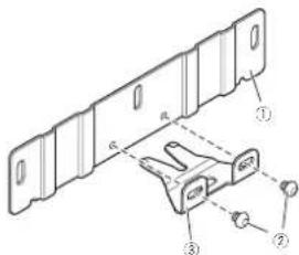
① Sunvisorthicknessadjustmentplate
② Longitudinal direction adjustment screws
③ Longitudinal direction adjustment plate
4Alignthescrewholesonthesunvisor thicknessadjustmentplatewiththoseon themountingbracket,andtightentheremainingscrewsthatwereremovedatthe originalpositions.
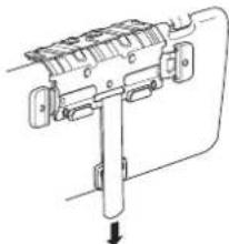
InstallingMainUnit
1AligntheHUDlocklevertothelock-releaseposition.
Pullthel UBlocklever, and sliceit to the lock-release position.
①Lock-releaseposition
②HUDlocklever
- Dorothold:themovingpartonthamounting bracketwhenoperatingtheHUDlocklever.If holdingthemovngpart,theHUDlocklever cannotbomoved
① Movingpart
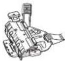
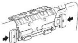
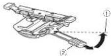
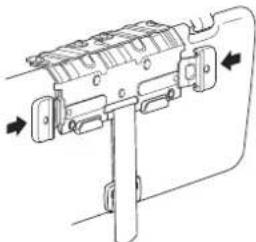
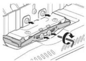
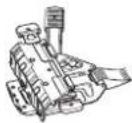
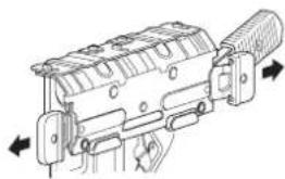
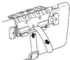
2Releasethelockplatesonthemounting bracket.
Pullthelockplatesonthemountingbracketto theleftandrighttoreleasethe ock,

natural_image
Technical line drawing of a firearm internal component with directional arrows indicating movement (no text or symbols)3Adjustthemountingbracketthickness.
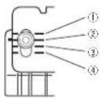
Align helines onhemountingbracket to the scale marks located at the land right on the sunvisorthickness adjustment plate according to the thickness softness advisor and thontightenthreescrews.
①Mountingbracket
②Sunvisorthicknessadjustmentplate
• The approximate figurestorthosca omarks on the unvisorthickness adjustment plate (medium) areas follows (the illumination shows the incontnomounting brackets aligned to thosca omark of 22mm).
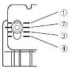
①20mm
InstallingMainUnit
②22mm
24mm
④26mm
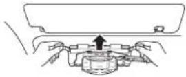
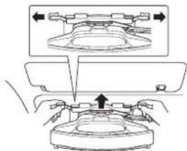
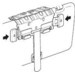
4Mountthemountingbrackettothesun visor.
Pushthesunvisoruptothehorizontalposition. Holdtheleftandrightencosflockplatesonthe mountingbracket, andmountthemounting brackettothesunvisorbypushingthemountingbracketallthewayin.
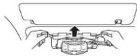
- If themounting bracket cannot be fully pushpin, the mounting bracket thickness needstobe increased. Removethe mounting bracket from the sunvisor return ostep3 andad us these a eposition, and then mountthemounting bracket to the sunvisor again.
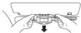
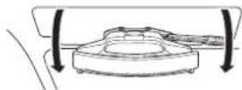
5Pushthesunvisordowntothevertical position.
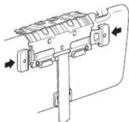
6Lockthemountingbracket.
Pushinthelockplatesfromthelettandright firmlylo ockthemountingbracket.
- If the lock plates cannot be fully pushed, then mounting bracket thickness needs to be increased. Removethemount ring bracket from the sunvisor return to step 3 and adjust the scale position, and then mount the mounting bracket to the sunvisor again.
7Checkthatthemountingbracketis mountedsecurely.
Pushlresunvisorbacklothehorzontalposition.
Push the mounting bracketback and forth to make sure that the mounting bracket is mounted securely.
- If themountingbracket can be removed from the sumy soreasily, then mount ngbracket; thickness needs to be decreased. Remove the mount ngbracket from the sunvisor, return to stop3 and just the scale posit on, and then mount the mount ngbracket to the sun visor again.
8Removethemountingbracket.
Pushlresunvisordownloltheverticalposition andpullthelockplatestothelettandrigattore-leaselhelock.
Pushlinesunvisor-uplothenorizontalposition andromovothemountingbracketfromthesun visor.
InstallingMainUnit
9Checkiftheadjustedthicknessofthe mountingbracketsappropriate.
Pushinthelockplatesontremountingbracket fromtheleftandrightfirmlytolockt.
Check that the mounting bracket cannot be mounted to these unvisores easily whilst the lock plates are locked.
If the mounting bracket cannot be mounted to the unvisoreasily, the thickness is correct.
- If the mounting bracket can be mounted to the sunvisora easily whilst the lock plates are locked themounting bracket thickness is not appropriate.
Removethemountingbrackelfromthesun visor, return to step3 and adjust the scale position, another mounthemountingbracket to the sun visor again.
10Mountthemountingbracketofwhich thicknesswasadjustedtothemainunit.
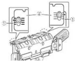
Check that the diffuser and combNER of the main unit are closed, and align the IUDlock ever on the amounting bracket to the lock release position.
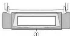
Mainunit:

①Combiner
②Diffuser
Mountingbracket:
①Lock-releaseposition
②HUDlocklever
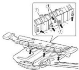
Secure themounting bracket and rain until four places at the ironlandback using the supplied mountingscrews.
Mainunitfront:
①Groove
InstallingMainUnit
②Alignthebosseswiththegroove.
Mainunitback:
①Alignthebosseswiththegroove.
②Groove
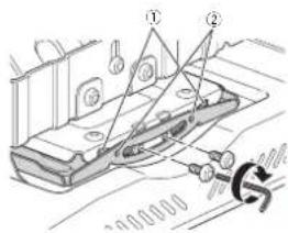
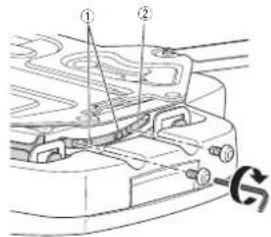
11Loosenthefourmountingscrewsthat weresecuredinstep10oneturn.
12Loosenthelongitudinaldirectionadjustmentscrewsontheunitoneturn.
Mainunitfront:

natural_image
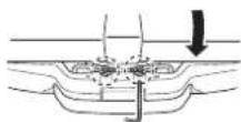
Technical line drawing of a vehicle chassis with two arrows indicating movement or force (no text or symbols present)13Mounttheunittothesunvisor.
Pull the lockplates on themountingbracket to the left and right release the lock.
Pushthesunvisoruptothehorizontalposition.
Holoth-cleftandrightendsoflockplatesontnemountingbracket,andmountheunitolnesunvisorbypusningthemountingbracketallthewayn.
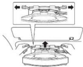
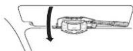
14Pushthesunvisordowntothevertical position.
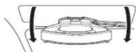
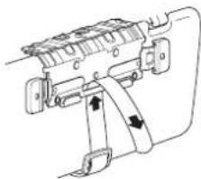
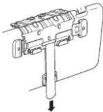
15Securetheunittosunvisorwithafall
preventionbelt.
Pullthefal preventionbellforwardfromthe backofthosunvisorthatwaspushedcownto trevert calposition.
natural_image
Pure mechanical diagram showing a lever mechanism with no text or symbolsInstallingMainUnit
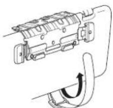
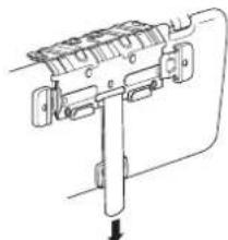
Passthefallpreventionbeltthroughasshown intheillustration.

natural_image
Technical line drawing of a mechanical device with no visible text or symbolsPullthetallprevent onbeltdownwardandsecurellasitispuIeddownward.

natural_image
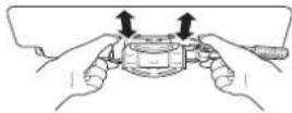
Technical line drawing of a mechanical assembly with no visible text or symbols16Lockthemountingbracket.
Pushinthelockplatesfromtheleftandright firmlytolockthemountingbracket.
natural_image
Technical line drawing of a mechanical device with directional arrows indicating movement (no text or symbols)17Pushthesunvisoruptothehorizontal position.
18Lockthemainunitposition.
PulltheHUDlocklever, and slide it to the lock position.
①Lockposition
Thema nun slidesforwardandtheunitpositionislocked.
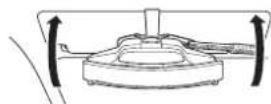
19Adjustthetiltofthemainunit.
Adjust the angle to level the main unit.
InstallingMainUnit
Tillthesunvisorverticallyabout20degreesand firmlytightenthetwomcountingscrewsatthe backoffnemainunitthatwerelcoosenedinstep 11.
- Ifthecombinerprotectionsheetinterferes withtheadustment.removelheprotection sheet. Attachthecombinerprotectionsheet, againafterheadjustmentisfinshed.
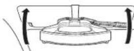
20Adjustthedirectionofthemainunit.
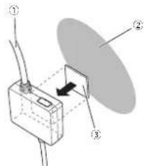
Openthediffuserandcominerofthemain unit.
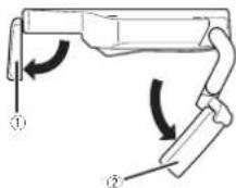
①Diffuser
②Combiner
Adjusted direction of the main unit to align the diffuser and combiner in the travelling direction.
①Aligntheunitinthetravellingdirection
①Adjustthecombinersothatthediffuser canbedisplayedinthecentreofthe combiner.
- Bosurotoadjustthem a nunit stobe alignedirthetravellingdirection.
21Unlockthemainunitposition.
PulltheHUDlocklever,andslicciftothelock-releaseposition.
InstallingMainUnit
①Lock-releaseposition
TremainunitslidesbackwardandtheunilpositionSunlocked.
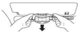
22Removetheunitfromthesunvisor.
Closethediffuserandcombnerofthomain unit,and thenpushthesunvisordowntothe vertical position.
Pullthelockplatesonthemountingbracketto theleftandorigntlore easethelock.Unlockthe fallpreventionbell.Pushthesunvisoruptothe horizontalposition,andthenremovethemountingbracketfromthesunvisor.
• Becarefulnottocausetheurittofal out.
23 Firmlytightenthemountingscrewsat thefrontofthemainunit.
Firmlyghtenthetwomountingscrewsatthe frontofthemainunitthatwereloosenedinstep 11andnetwolongitudinaldirect onadjustment screwsthatwereloosenedinstep 12.
24Mounttheunittothesunvisor.
Perform the operation from steps 13 to 17 to mount the unit to the advisor.
• Align the LCD clock over-tothelock release position before mounting the urittothesun visor.
- If there is a gap between vehicle's scaling and sun vision when the horizontal position, attach the sun vision cushion to the fetal prevention belt.
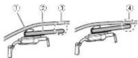
①Vehicle'sceiling
②Sunvisor
③ Gapbetweenthevehicle'sceilingand sunvisor
④Nogapbetweenthevehicle'sceiling andsunvisor
- When attaching as unvisor cushion affix the sum sorcush entothes sum sorcush on no car attach it to the total prevention belt, and then secure the full prevention belt.
①Fallpreventionbelt
②Sunvisorcushion
③Sunvisorcushionholder
InstallingMainUnit
①Sunvisorcushion
②Fallpreventionbelt
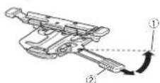
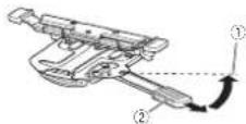
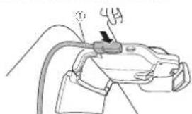
25Connectthepowercabletotheunit.
natural_image
Line drawing of a mechanical device with a handle and cable (no text or symbols)① Powercable
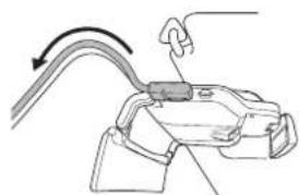
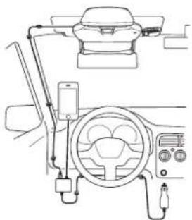
26Routethepowercable.
Routethepowercablesothat:thecablewillnot interferewit:driving,andensurethedriverhas asafetielo:vision.
natural_image
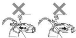
Diagram of a mechanical clamp or bracket with a hook and arrow indicating direction (no text or symbols)- Adjust the powercablesothality will not be structured driver's vision. - Routethecablesothality will not interfere with the backward and forward movement of them in unit when operating the HUDlock lever.
Routethepowercablebyfixingthepointswith clampscommerciallyavailable.
natural_image
Line drawing of a car interior showing steering wheel, dashboard, and steering wheel (no text or symbols)① Fixthecablewithclampscommercially available.
- Donotaffixormounttnecabletothewin-screen.
- Donotroule the powercable at the foot of the driver's seat. There is a risk that the powercable got a rounded undorthorake pedaland interferes with driving, resulting in a serious accident.
27Lockthemainunitposition.
PulltheHUDlocklever, and slide it to the lock position.
InstallingMainUnit
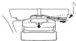
①Lockposition
The main units slices forward and the unit position is locked.
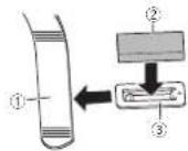
28Securethepowercable.
Attachthedouble-s dectapetothecconnection boxofthepowercable and thenattachthecon- nctionboxtoalocationwherethacablecanbe securefirmly.
①Powercable
② Dashboardsideetc.
③Double-sidedtape
Fixlthecablewithclarnoscommerciallyavailable,

natural_image
Line drawing of a car steering wheel and dashboard (no text or symbols)- Never install the power cableinalocation where the cable cannot be secured due to vehicle vibration, etc.
- If the cable cannot be secured with the application double-sided tape, secure it firmly using commercial yava lab double-sided tape, etc.
• FirmlysecureaniPhoneorAndroiddevice in aholdercommerciallyavailable.
- Insert nec garette a ugofthepowarcable into the garettesocketontnevehiclewith the E Dindicatorface-upsothatthadriver canseat.
TheLEDindicatoronthecigarettepluglights greenifthepoweristurnoon.
①LEDindicator
Formorocetails,robertoConnectingthe powercabletothecigarettesocletonpage16.
InstallingMainUnit
29Removethecombinerprotectionsheet.
Check that the power cable is connected and routed correctly, and then removed the combiner protection sheet.
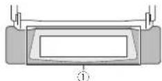
Afterinstallation

CAUTION
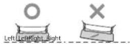
- Checkiftheunitis installed correctly. In the following cases, return to step 1 and install the unit correctly.
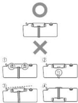
①Thelockplatesarenotfixed.
②Theunitisnotsecuredwithafallpreventionbelt.
③Theunitisinstalledobliquely.
④Positionoftheunitisinstalledreversed.
•Closethediffuserwhennolusingtheunit.
- When removing the un-tron thosunvisor and storing it besurelocoselhediffuser and combiner. Donotieve the un tin placesexcosedtodirectsunlight, suchasonadsh board. The diffuser combiner may concentrate light into an intense beam, causing smokeoffire.
Connecting the powercable tothecigarettesocket
● Firmlyconnectthecigaretteplugofthe powercablebyinsertingitintothecigarette socketonthevehicle.
The LED indicator on the cigarette plug lights green if the power is turned.
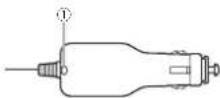
①LEDindicator
Notes
- Insert the cigarette plug of the powerable into the cigarettes socket on the vehicle with the LED indicator face-up so that the driver can see it.
- Ithrel E. Dindicatordoesnottumortwhen thevehicleengineisturnedoff, disconnect, thepowercablefromtheo.garcttesocketon thevehicle. Failurebosowildrainthevehiclebattery.
SettingyouriPhoneorAndroiddevice
ConnectingyouriPhoneor Androiddevicetotheunit
ForiPhoneusers
- Use the cables uppli cowith the iPhone. Don o le a v e t h e c a b l e i n t h e v e h i c l e. The cables uppli cowith the iPhone is not de signed for use in a v e h i c l e.
ForAndroiddeviceusers
- UseaUSB-microUSBdalacommunication cableof1morless.Achargecablecannot beused.
1ConnecttheUSBcabletoyouriPhoneor Androiddevice.
2ConnecttheotherendofUSBcable firmlytotheconnectionboxofthepower cable.
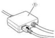
①Connectionboxofthepowercable Connectionoverview:
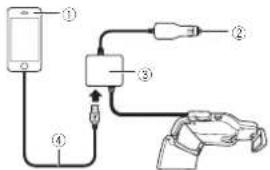
①iPhoneorAndroiddevice
②Tothecigarettesocket
Connectionboxofthepowercable
④USBcable
Installingthenavigation application
InstallthenavigationapplicationloyouriPhone orAndroiddevcobeforeutilisingthisunit. Youcandownloadthenavigationapplication fromiTunesApoStoreorGooglePlay. Formerdetailsonnavigationapplication, rctor tothe'ollowingsile. http://www.cioneer.eu/navigalehud
Startingthenavigation application
When you set the navigation application for the first time, start the application yourself. The application will start automatically from the next timestamp of iPhone or Android device is connected to the unit.
CAUTION
- Forutilisingthenavigationapplication,you needtopurchasetheNavGateHUDSupport first.PurchasetheNavGateHUDSupportin theapplicationbyfollowingtheinstructions onthescreen. - Theinternetconnectionisrequiredtopur chasetheNavGateHUDSupportL
Notes
•ForiPhoneusers
If the application does not start automatically when the iPhone is connected to the unit, tap "Allow in the popup that appears on the iPhone.
•ForAndroiddeviceusers
SettingyouriPhoneorAndroiddevice
If the application does not start automat call when the Android device is connected to the unit, tap the application in the popup that appears on the Android device. If you select the checkbox and then select the application in the popup, the popup will not appear from then next time.
Displaymodes
FlxtypesofviewareavailableforthisunitARview(lowspeedmodeandhighspeedmode)listview(lowspeedmodeandhighspeedmode),junctcreview,rouseeview,andclockview If the communication between the unit and then navigation application is established, either the following views appears.
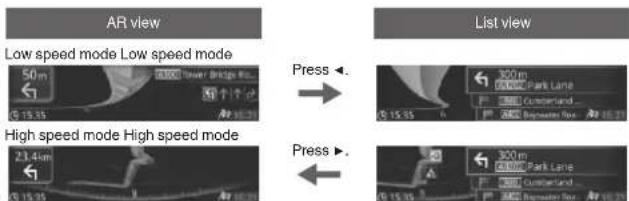
If a vehicle approaches a junction If a vehicle approaches a junction
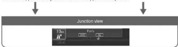
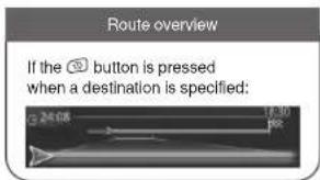

Notes
- The low speed mode of the Review is displayed when Destination is not specified.
- Formoredetailsontheviews,refertothecoperationmanual.
Whenyoufinishwithininstallationandconnection
Adjustingthedisplaysettings
When you finish with the installation and connection, tumontneunit(start the vehicle engine) and adjust the combining angles that the image can be seen.
Note
Thescreenmayro:beabletobeseenclearly dependingonthescreenbrightnessandsurroundingconditions.Adjustthescreenbrightnessproperly(referto:Adjustingthedisplay brightnessonpage20),ormovethevehicletoa locationwherethodisplayismoreclearlyvisible, andthenoperatetheunit.
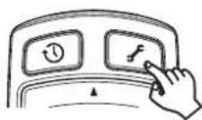
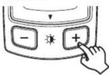
1Pressthe
button.
2Pressthe▲/▼buttontoselectDisplay Settings, and then pressthe▶ button.
3Pressthe▲/▼buttontoselectasetting item, and then pressthe▶ button.
Position
Adjust the position of the displayed image.
1Pressthe▲/▼buttontoselectasetting item, and then pressthe▶ button.
| Position | |
| Horizontal Position | |
| Vertical Position | |
| SettingitemDescription | |
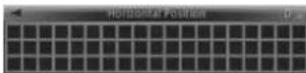
| HorizontalPosi-tion | Selectloadustthehorizon-talpositionofthed splayed image. |
| VerticalPosition | Selectloadustthevertical positionofthedisplayed image. |
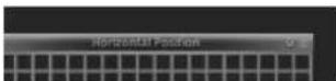
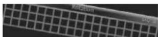
2Pressthe▲/▼buttontodisplaythegrid patterninitsentirety.
Ex.:Whenitiscorrectlyadjusted
Ex.:Whenitisnotcorrectlyadjusted
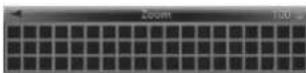
Zoom
Adjustthesizeofthedisplayedimage
- Pressthe ▲/▼ buttonodisplaythegrid patterninitsentirety.
Whenyoufinishwithinstallationandconnection
Rotation
Adjusttherolation of the displayed image.
●Pressthe▲/▼buttontolevelthegrid pattern.
Ex.:Whenitiscorrectlyadjusted
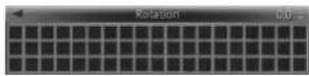
Ex.:Whenitisnotcorrectlyadjusted
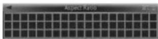
AspectRatio
Adjust the aspect ratio of the displayed image.
●Pressthe▲/▼buttontomakethegrid patternrectangular.
GeometricCorrection
Correctthedistortionoffredisplayedimage.
1Pressthe▲/▼buttontoselectasetting item, and then pressthe▶ button.
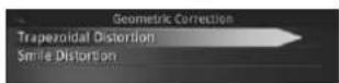
SettingitemDescription
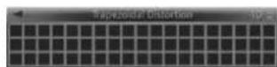
| TrapezoidalDistortion | Selectocorrectthetrapezoidaldistortion. |
| SmileDistortion | Selectocorrectthesmiledistortion. |
2Pressthe▲/▼buttontomakethegrid patternrectangular.
Ex.:Adjustingthetrapezoidaldistortion
WhiteBalance
Adjust the white balance of the displayed image.
1Pressthe▲/▼buttontoselectasetting item, and then pressthe▶ button.
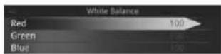
SettingitemDescription
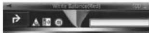
| Red | Selecttoadjustthered tones. |
| Green | Selecttoadjustthegreen tones. |
| Blue | Selecttoadjusttheblue tones. |
Whenyoufinishwithininstallationandconnection
2Pressthe▲/▼buttontoadjustthe brightness.
Ex.:Adjustingtheredcolour
Beforedriving
Configuringtheunit functionsettings
Unitfunct onsettingscanbeconfigurefrom theSettingsscreen.

CAUTION
- This unit is ab esoperation of the unit whilst the vehicle is in motion. Park the vehicle is a safe place and apply an handbrake before cooperating this unit.
- If the vehicle starts moving whilst setting the unit functions, the Settings screen will close automatically.
●Pressthe
button.
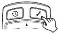
TheSettingsscreenappears.
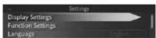
MenuDescription
DisplaySettings
Adjusthedisplaysett ngs forprojected images.
FunctionSettingsSetthefunctionsettings.
LanguageSetthedisplaylanguage.
About
Confirm the unit software version and legal notices.
ResetAllSettingsRestoredefaultsettings
Notes
- FunctionSettingscanonlybesetwhenthe communicationwiththeravigationapplicationhasbeenestablished.
- Pressthe buttonoclosetheSettings screen.
• Fordetails refer to the operation manual.
Adjusting the angle of the combiner
Adjust the angle of the combinator these at position.

CAUTION
Holdentothedgessoftthecombinerwhenadjustingtheangle.
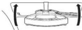
10penthediffuserandcombiner.
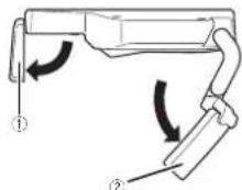
①Diffuser
②Combine
Beforedriving
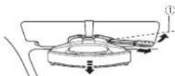
2Adjustthecombineranglesothatthe wholediffusercanbereflectedonthe combiner.

natural_image
Illustration of a hand holding a pen above a device with a magnified view below (no text or symbols)①Adjustthecombinersothatthediffuser canbedisplayedinthecentreofthe combiner.
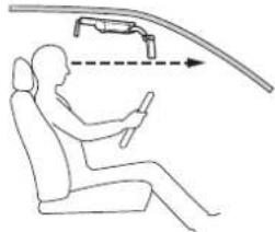
Whengettinginandoutof thevehicle
Beforeuse,besure lo check that relowerend of the combineris abov your line of sight when you sit in the scat and lock straight forward in the actual driving position. If the lower end of the combiner is below your line of sight don't use the unit, Folothecombiner not the storage position to ensure field of vision for driving.
natural_image
Line drawing of a person seated in a car with a curved road and directional arrow indicating motion (no text or symbols)Adjustingthedisplay brightness
Thedimmerfunctiononthisunitadjuststhe displaybrightnessautomaticallyaccordingto theamountlofambenlight. Thedisplaybrightnesscanbeadjustedman- uallyusingthe /button.

CAUTION
Before using the unit at night time on dark places such as a tunnel, adjust the brightness of the unit properly so that will not interfere with driving. Failure to cosomay cause an accident.
Beforedriving
●Pressthe/button:
Note
Changingthebrightnessmayalsocausethe
d sp ayhuetochange.
Section
Section
Précautions
01 Précautions
Remarquesuriemanueide
fonctionnement22
Précautionsderaccordement28
Connex onducabled'alimentation28
Préventioncontrelebruit28
1 support demor lage
1câoled al merlation
1amortisseurdepare-sole I

1 bandeadnosvoudoub elace
Précautionsderaccordement

PRÉCAUTION
natural_image
Diagram of a USB cable connector with an arrow pointing to the port (no text or symbols present)①Fusible(3A)
①Appareilprincipal
②Câbled'alimentation
①Plaquederéglaged'épaisseurdupare-
soleil
②Visderéglagededirectionlongitudinale
③Plaquederéglagededirectionlongitudinale
3Fixezlaplaquederéglagededirection longitudinaleàlaplaquederéglaged'épaisseurdupare-soleilàutiliser.
①Plaquederéglaged'épaisseurdupare-
soleil
②Visderéglagededirectionlongitudinale
③Plaquederéglagededirectionlongitudinale
①Piécemobile
2Libérezlesplaquesdeverrouillagedu supportdemontage.
Tirezlesplaquesdeverrouillagedusupportde montageverslagauchectladroitepourlibérer leverrou.
natural_image
Technical line drawing of a firearm internal component with arrows indicating movement (no text or symbols)
①20mm
②22mm
③24mm
④26mm
4Installezlesupportdemontagesurle pare-soleil.
Reevezlepare-soleilenpositionhorizontale. Tenczloscxtrém tõsgauchoctdroitodosplaquesdevorrouillagousupportdemontage, puisinstallezlesupportdemontagesurlepare-sole-enl'engageantcomplèlement.
8Retirezlesupportdemontage.
Abaissezlepare-soleilenpositionverlcale,puis tirczlespiquesdeverrouillageverslagauche etladro tepourlibérerleverrou.
Installationdel'appareilprincipal
Relevezlepare-soleilenpositionhorizontale, puisrelrezlesupportdemontagedupare-soleil.
①Fente
natural_image
Technical line drawing of a mechanical component with two arrows indicating features (no text or symbols present)13Installezl'appareilsurlepare-soleil.
Tirezlesplaquesdoverrouillagedusupportde montageverslagaucheeeltacroitepourlibérer leverrou.
Relevezlopare-solcelenpositionhorizontale. Terezlosextrémitésgauchecectorodosolaquesdeverrouillagedusupportde montage. pulinstallezl approvalsurlopare-solcelionengagecantcomplètementlesupportdementnage
14Abaissezlepare-soleilenpositionverticale.
Installationdel'appareilprincipal
natural_image
Pure mechanical diagram showing a lever mechanism with no text or symbolsFaitespasser asanglecantichutecommelindicuédans Illustration.
natural_image
Technical line drawing of a mechanical assembly with no visible text or symbolsAbaissezlasangleantichuteeff xez-la.
natural_image
Pure mechanical assembly diagram without any text, numbers, or symbols16Fixezlesupportdemontage.
Appuyezfermentsurlesplaqueseverrouillageverslagaucheelladroitepourfixerlesupportdemontage.
natural_image
Technical line drawing of a mechanical device with arrows indicating assembly or movement (no text or symbols)17Relevezlepare-soleilenpositionhorizontale.
18Verrouillezlapositiondel'appareilprincipal.
①Afficheur
②Multiplexeur
natural_image
Diagram of a mechanical component with directional arrows indicating motion or flow, no readable text or symbols present.24Installezl'appareilsurlepare-soleil.
①Amortisseurdepare-soleil
② Sangleantichute
natural_image
Line drawing of a mechanical device with a handle and cable (no text or symbols)①Câbled'alimentation
26Acheminezlecabled'alimentation.
natural_image
Diagram of a mechanical device with a curved arrow indicating motion or force (no text or symbols)natural_image
Top-down line drawing of a car interior showing steering wheel, dashboard, and steering wheel (no text or symbols)natural_image
Line drawing of a car steering wheel and dashboard with no text or symbolsInstallationdel'application denavigation
Installez applicationdanavigationsurvotre iPhoneoupériphériqueAndroidavanto'utiliser celappareil.
natural_image
Illustration of a hand holding a tool with an arrow indicating motion, above a device with a screen (no text or symbols)natural_image
Line drawing of a person sitting in a car with a car above showing a vehicle trajectory (no text or symbols)natural_image
Diagram of a USB cable connector with an arrow pointing to the cable (no text or symbols present)①Fusibile(3A)
①Partemobile
natural_image
Technical line drawing of a firearm internal component with arrows indicating movement (no text or symbols)①20mm
②22mm
③24mm
④26mm
4Fissarelastaffadimontaggioalparasole.
①Fessure
②Allineareimozziallefessure.
① Allineareimozziallefessure.
②Fessure
natural_image
Technical line drawing of a mechanical component with two arrows indicating assembly or movement (no text or symbols present)natural_image
Technical line drawing of a mechanical component with a curved arrow indicating rotation (no text or symbols)natural_image
Technical line drawing of a mechanical device with labeled components (no text or symbols)Tirarelacinghiaarticaculaversoilbassoefissarlamentrevieneliralairbasso.
natural_image
Technical line drawing of a mechanical device with a downward arrow indicating force or movement (no text or symbols present)natural_image
Technical line drawing of a mechanical device with arrows indicating assembly or movement (no text or symbols)natural_image
Technical diagram of a mechanical component with directional arrows and a circular motion symbol (no text or labels)24Installarel'unitàsulparasole.
①Cuscinettoperilparasole
②Cinghiaanticaduta
natural_image
Line drawing of a mechanical device with a tool and cable (no text or symbols)natural_image
Diagram of a mechanical device with a tool and curved arrow indicating motion (no text or symbols)natural_image
Diagram of a car interior showing steering wheel, dashboard, and steering wheel (no text or labels)①Fissareilcavoconmorsettidisponibiliin commercio.
natural_image
Line drawing of a car dashboard and steering wheel assembly (no text or symbols)natural_image
Illustration of a handheld tool interacting with a device, showing motion capture (no text or symbols)natural_image
Line drawing of a person sitting in a car with a car above showing a vehicle mounted on a lift (no text or symbols)natural_image
Two identical rounded rectangular shapes with no text, numbers, or symbols
Italiano
631
Sección
Precauciones
01 Precauciones
natural_image
Diagram showing a USB cable connector with an arrow pointing to the port (no text or symbols present)Prevenciónderuido
①iPhoneodispositivoAndroid
②CableUSB
③Cabledealimentación
④Alconectordealimentación
⑤IndicadorLED
⑥Interruptordetamānodelconector
⑦Alencendedor
ParausuariosdeiPhone
①Fusible(3A)
①Unidadprincipal
①Piezamóvil
2Sueltelasplacasdebloqueodelsoporte.
Tirede asplacasdebloqueode soporlehacia fucraparadesbloquearlo,

natural_image
Technical line drawing of a firearm internal component with arrows indicating movement (no text or symbols)3Ajusteelgrosordelsoporte.
①Soporte
②Placadeajustedegrosordelparasol
①Ranura
②Alineelasguiasconlaranura.
①Alineelasguiasconlaranura.
②Ranura
natural_image
Technical line drawing of a mechanical component with two arrows indicating assembly or movement (no text or symbols present)13 Montelaunidadenelparasol.
natural_image
Mechanical assembly diagram showing a clamping mechanism with no visible text or symbolsSección
natural_image
Technical line drawing of a mechanical device with no visible text or symbolsnatural_image
Pure mechanical assembly diagram without any text, numbers, or symbols16Bloqueeelsoporte.
Paraello.empu:elasplacasdebioquechacia dentro.

natural_image
Technical line drawing of a mechanical device with directional arrows indicating movement or force (no text or symbols)17Tiredelparasolhaciaarribahastaque estéhorizontal.
24Montelaunidadenelparasol.
natural_image
Technical line drawing of a mechanical component with labeled parts (no readable text or symbols)natural_image
Diagram of a mechanical device with a curved arrow indicating direction (no text or symbols)natural_image
Line drawing of a car interior showing steering wheel, dashboard, and steering wheel (no text or symbols)①Fijeelcableconlaabrazaderadisponible enelmercado.
• Nofijecmonteelcae alparabrisas
Sección
①Cabledealimentación
②Lateraldelsalpicadero,etc.
③Cintadedoblecara
Fijeelcaoleconlaabrazaderacisonibleenel mercado.
natural_image
Line drawing of a car dashboard and steering wheel assembly (no text or symbols)①iPhoneodispositivoAndroid ②Alencendedor ③Cajadeconexióndelcabledealimentación ④CableUSB
natural_image
Illustration of a hand holding a pen with a curved arrow indicating motion, above a device component (no text or symbols)natural_image
Line drawing of a person seated in a car with a car above showing a vehicle mounted on a curved road (no text or symbols)natural_image
Diagram of a USB device showing port and cable connections (no text or symbols)①Sicherung(3A)
natural_image
Technical line drawing of a mechanical assembly with labeled component (no text or symbols present)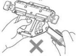
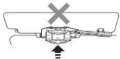
natural_image
Illustration of hands using a handheld device to adjust or install a mechanical component, with a cross mark indicating cancellation (no text or symbols present)①Bewegliche Teile
natural_image
Technical line drawing of a firearm internal component with directional arrows indicating movement (no text or symbols)① Montagehalterung
①20mm
②22mm
③24mm
④26mm
natural_image
Technical line drawing of a mechanical component with two arrows indicating assembly or movement (no text or symbols present)natural_image
Pure mechanical diagram showing a lever and housing assembly without any text, numbers, or symbolsnatural_image
Technical line drawing of a mechanical device with no visible text or symbolsnatural_image
Pure mechanical assembly diagram without any text, numbers, or symbolsnatural_image
Technical line drawing of a mechanical component with arrows indicating assembly or movement (no text or symbols)①Streuscheibe
②Combiner
natural_image
Diagram of a car interior showing dashboard, steering wheel, and dashboard-mounted device (no text or labels)natural_image
Diagram of a mechanical component with directional arrows indicating motion or flow, no readable text or symbols present.natural_image
Technical line drawing of a mechanical clamp or connector assembly (no text or symbols)①Stromkabel
natural_image
Diagram of a mechanical device with a curved arrow indicating direction (no text or symbols)natural_image
Diagram of a car interior showing dashboard, steering wheel, and dashboard frame (no text or labels)natural_image
Line drawing of a vehicle steering wheel and dashboard (no text or symbols)natural_image
Illustration of a hand holding a pen above a device with a magnified view below (no text or symbols)natural_image
Line drawing of a person seated in a car with a car above showing a vehicle trajectory (no text or symbols)natural_image
Two horizontal oval shapes with rounded ends, one black and one white, against a white background (no text or symbols)Deutsch
105de
Hoofdstuk
natural_image
Diagram of a USB cable connector with an arrow pointing to the port (no text or symbols present)Ruisvoorkomen
①iPhoneofAndroid-apparaat
②USB-kabel
③Stroomkabel
④Naarstroomaansluiting
⑤LED-indicator
⑥Schakelaarstekkerformaat
⑦Naaraansluitingvansigarettenaansteker
①Zekering(3A)
①Bewegendgedeelte
2Maakdevergrendelingsplatenopdebevestigingsklemlos.
natural_image
Technical line drawing of a firearm internal component with directional arrows indicating movement (no text or symbols)①Bevestigingsklem
①20mm
22mm
③24mm
①26mm
①Groef
natural_image
Technical line drawing of a mechanical component with mounting holes and internal features (no text or symbols)13Plaatshettoestelopdezonneklep.
Hoofdstuk
natural_image
Pure mechanical diagram showing a lever and handle without any text, numbers, or symbolsLe doevalbeveilig ngsriemzoalsinde illustratie wordlgeloond.
natural_image
Technical line drawing of a mechanical device with no visible text or symbolsTrekoevalbeveilig ngsriemnaarbenedenaan enzelhemdanvast.
natural_image
Pure mechanical assembly diagram without any text, numbers, or symbols16Vergrendeldebevestigingsklem.
Duwdevergrendelplaten inksenrechtsnaar binnenomdebevest gingsklemstevigvastle zetten.
natural_image
Technical line drawing of a mechanical device with arrows indicating assembly or movement (no text or symbols)①Hettoestelafstelleninderijrichting
natural_image
Diagram of a mechanical component with rotating parts and directional arrows, no readable text or symbols present.24Plaatshettoestelopdezonneklep.
Voorstappen 13t/m 17uitomhettoestelopde zonnek eptebevestigen.
- BrengdeHUD-vergrendel ngshendelnaarde geoper depositievoor uhettoestel opdezon-noklapmonteart.
natural_image
Line drawing of a mechanical device with a cable and connector (no text or symbols)①Stroomkabel
natural_image
Diagram of a mechanical assembly with a tool and curved arrow indicating motion (no text or symbols)natural_image
Diagram of a car interior showing steering wheel, dashboard, and steering wheel (no text or labels)Hoofdstuk
①Stroomkabel
②Dashboarde.d.
natural_image
Line drawing of a car steering wheel and dashboard with attached sensors (no text or symbols)natural_image
Illustration of a hand holding a pen or tool with a curved arrow indicating motion, above a device with a screen (no text or symbols)natural_image
Line drawing of a person seated in a car with a car above showing a vehicle mounted on a lift (no text or symbols)natural_image
Diagram of a USB cable connector with an arrow pointing to the port (no text or symbols present)①Подвижная часть
natural_image
Technical line drawing of a firearm internal component with directional arrows indicating movement (no text or symbols)natural_image
Technical line drawing of a vehicle chassis with two wheels and mounting brackets (no text or symbols)natural_image
Diagram of a mechanical device with hoses and a curved arrow indicating rotation (no text or symbols)natural_image
Technical line drawing of a mechanical device with no visible text or symbolsnatural_image
Pure mechanical assembly diagram without any text, numbers, or symbolsРаздел
natural_image
Technical line drawing of a mechanical device with directional arrows indicating movement or assembly (no text or symbols)natural_image
Line drawing of a mechanical device with a handle and cable (no text or symbols)①Кабель питания
natural_image
Diagram of a mechanical assembly with a hook and directional arrow (no text or symbols)natural_image
Line drawing of a car interior showing steering wheel, dashboard, and steering wheel (no text or symbols)natural_image
Line drawing of a car steering wheel and dashboard (no text or symbols)natural_image
Illustration of a hand holding a wrist with a finger and wristband, showing motion direction (no text or symbols)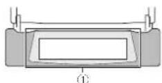
natural_image
Line drawing of a person seated in a car with a car above showing a vehicle trajectory (no text or symbols)©2013PIONEERCORPORATION.Allrightsreserved.
©2013PIONEERCORPORATION.Tousdroitsdereproductionetdetraductionréservés.
PIONEERELECTRONICSAUSTRALIAPTY.LTD.
5ArcoLane,Heatherton,Victoria,3202Australia
TEL:(03)9586-6300
PIONEERELECTRONICSOFCANADA, INC.
340FerrierStreet,Unit2,Markham,OntarioL3R2Z5,Canada
TEL:1-877-283-5901
TEL:905-479-4411
PIONEERELECTRONICSDEMEXICO.S.A.deC.V.
Blvd.ManuelAvilaCamacho13810piso
Col.LomasdeChapultepec,Mexico,D.F.11000
TEL:55-9178-4270
先锋股份有限公司
台北市内湖區瑞光路407號8樓
電話:886-(0)2-2657-3588
先锋電子(香港)有限公司
香港九龍長沙灣道909號5樓
電話:852-2848-6488