2CKA006599A2870 - Smart Home Busch-Jaeger - Free user manual and instructions
Find the device manual for free 2CKA006599A2870 Busch-Jaeger in PDF.
| Product type | Universal relay insert for smart home |
| Reference | 2CKA006599A2870 (model 6401U-102) |
| Brand | Busch-Jaeger |
| Category | Smart home |
| Power supply | 230 V ~, ±10 %, 50 Hz |
| Power consumption | < 1 W |
| Max. switching voltage | 250 V ~ |
| Max. switching current | 2300 W/VA |
| Protection type | IP 20 |
| Ambient temperature | -20 to +55 °C |
| Number of buttons/additional stations | Unlimited |
| Dimensions (approx.) | 71 x 71 x 35 mm (flush-mounted) |
| Weight (approx.) | 100 g |
| Main functions | Switching of incandescent lamps, halogens, fluorescent tubes; control via push buttons, IR, motion detectors, timer, presence indicator |
| Maintenance and cleaning | No maintenance required; clean with a dry cloth, avoid moisture |
| Safety | Follow DIN VDE 0100 standard; risk of death in case of different phases; IP20 |
| Spare parts | Not supplied; device not user-repairable |
| Repairability | 12-month warranty; repair or replacement by Busch-Jaeger |
| General information | Manual available in multiple languages; compatible with Busch-Jaeger products (sensors, IR controls, etc.) |
Frequently Asked Questions - 2CKA006599A2870 Busch-Jaeger
User questions about 2CKA006599A2870 Busch-Jaeger
0 question about this device. Answer the ones you know or ask your own.
Ask a new question about this device
Download the instructions for your Smart Home in PDF format for free! Find your manual 2CKA006599A2870 - Busch-Jaeger and take your electronic device back in hand. On this page are published all the documents necessary for the use of your device. 2CKA006599A2870 by Busch-Jaeger.
USER MANUAL 2CKA006599A2870 Busch-Jaeger
6810-xxx-10x, 6800-xxx-10x(M),
text_image
6067-xxx-10x Fig. 6Fig. 6
text_image
L1 LS16 N N L L 1 NContact de fermeture
6805U 6401U-102
Fig. 3

natural_image
Simple icon of a rectangular device with a curved top and rectangular body, no text or symbols present.text_image
6067-xxx-10x Fig. 6Fig. 6
Universal Relay Insert in stand-alone operation with pushbutton control
text_image
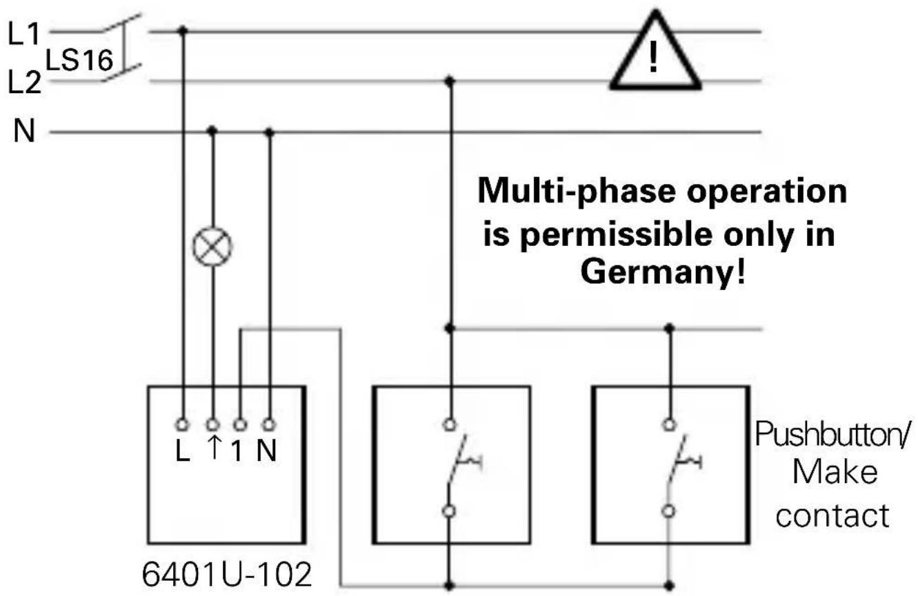
L1 LS16 L2 N Multi-phase operation is permissible only in Germany! L ↑ 1 N 6401U-102 Pushbutton/ Make contactNOTE
In the case of illuminated pushbuttons, only pushbuttons with a separate N terminal can be used. Illumination via parallel contacts is not permissible!
Fig. 2

Universal Relay Insert in conjunction with active extension 6805U and NO pushbutton
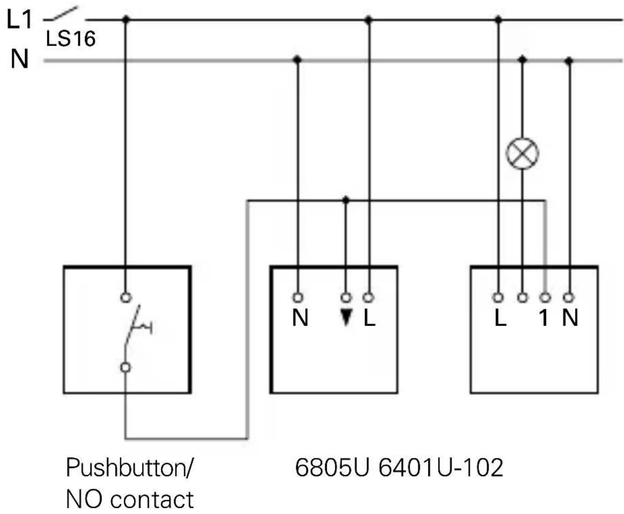
text_image
L1 LS16 N Pushbutton/ NO contact 6805U 6401U-102Fig. 3

IR receiving range
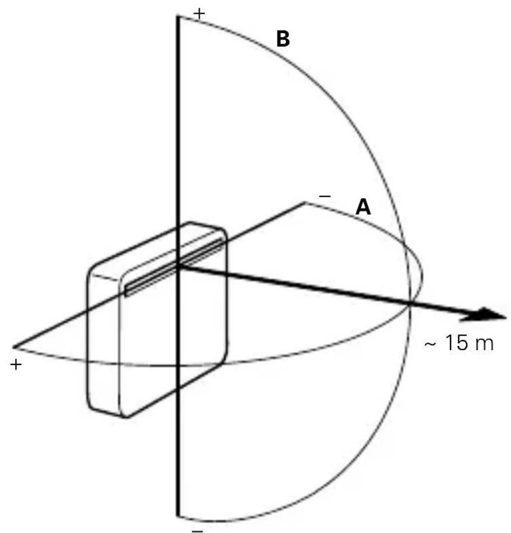
text_image
B A ~ 15 mFig. 4

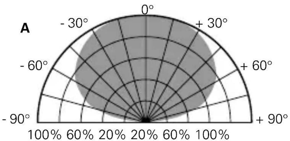
IR receiving range
radar
| Angle (°) | Value (%) | |---|---| | 0° | 100 | | +30° | 60 | | +60° | 40 | | +90° | 20 | | -60° | 10 | | -90° | 5 | | -30° | 10 | | 0° | 100 |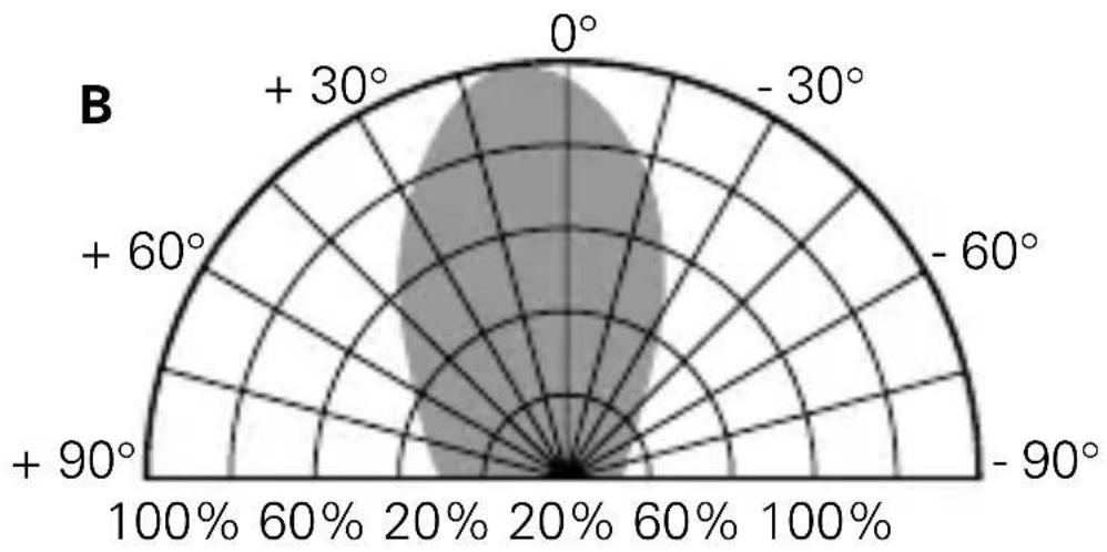
radar
| Angle (°) | Value | | --------- | ----- | | 0 | 100% | | +30 | 60% | | +60 | 20% | | -60 | 60% | | -90 | 100% |Fig. 5

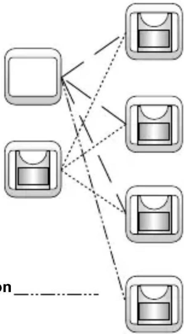
Possible combinations with Busch-Watchdog ^® , 180 FM Sensors
NC/NO Pushbutton
Extension Insert 6805U
flowchart
graph TD
    A["Device 1"] --> D["Node"]
    B["Device 2"] --> D
    C["Device 3"] --> D
    E["Device 4"] --> D
    F["Device 5"] --> D
    G["Device 6"] --> D
    H["Device 7"] --> D
    I["Device 8"] --> D
    J["Device 9"] --> D
    K["Device 10"] --> D
    L["Device 11"] --> D
    M["Device 12"] --> D
    N["Device 13"] --> D
    O["Device 14"] --> D
    P["Device 15"] --> D
    Q["Device 16"] --> D
    R["Device 17"] --> D
    S["Device 18"] --> D
    T["Device 19"] --> D
    U["Device 20"] --> D
    V["Device 21"] --> D
    W["Device 22"] --> D
    X["Device 23"] --> D
    Y["Device 24"] --> D
    Z["Device 25"] --> D
    AA["Device 26"] --> D
    AB["Device 27"] --> D
    AC["Device 28"] --> D
    AD["Device 29"] --> D
    AE["Device 30"] --> D
    AF["Device 31"] --> D
    AG["Device 32"] --> D
    AH["Device 33"] --> D
    AI["Device 34"] --> D
    AJ["Device 35"] --> D
    AK["Device 36"] --> D
    AL["Device 37"] --> D
    AM["Device 38"] --> D
    AN["Device 39"] --> D
    AO["Device 40"] --> D
    AP["Device 41"] --> D
    AQ["Device 42"] --> D
    AR["Device 43"] --> D
    AS["Device 44"] --> D
    AT["Device 45"] --> D
    AU["Device 46"] --> D
    AV["Device 47"] --> D
    AW["Device 48"] --> D
    AX["Device 49"] --> D
    AY["Device 50"] --> D
MOS - Fet Insert 6804U
Universal Dimmer 6590U-10x
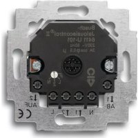
Universal Relay Insert 6401U-10x
Relay Insert 6812U-101
Fields of Application

The Universal Relay Insert 6401U-102 (hereinafter referred to as Insert 6401U-102) is a switch which is equipped with an extension input terminal to control
- incandescent lamps
- halogen lamps and
- LV halogen lamps with transformers, and
- fluorescent lamps
Insert 6401U-102 makes it possible, among other things, to use the following Busch-Jaeger products:
- IR Operating Element 6067-xxx-10x
- Operating Element 6543-xxx-10x
- NO pushbuttons (e.g., Art. No. 2020 US or 2021/6 UK) with extension operation
- FM Standard Sensors 6810-xxx-10x
- FM Comfort Sensors 6800-xxx-102(M)/103M/104(M)
- Timer Operating Element 6412-10x
- Presence Detector 6813
Important Information

If multi-phase (2-phase) operation is desired to control and operate the Insert 6401U-102, fulfillment of the following requirements in accordance with DIN VDE 0100 is imperative:
CAUTION DANGER!
If different phases are permissible on Insert 6401U-102, it must be ensured that all poles are disconnected in case of faults or when work is performed on the unit. This mode of operation is permissible only in Germany.
Documentation
In these Operating Instructions, not only the Standard Busch Watchdog ^® , Sensors (Art. No. 6810-xxx-10x), but also the Comfort Sensors (Art. No. 6800-xxx-10xM), are referred to as "FM Sensors". Please ensure that the appropriate types are used as specified in the description.
The type marking is on the back of the device in each case.
Technical Data

Rated voltage: 230 V \~ ± 10%, 50 Hz
Power input: < 1 ~W
Max. switching voltage: 250 V -
Max. switching current: 2300 W/VA
Max. ripple voltage 100 V with 100 m line
at extension: length
No. of pushbuttons: unlimited
Type of Protection: IP 20
Ambient temperature range: -20°C to +55°C
Switch off supply voltage!
Installation of the Insert 6401U-102
The Insert 6401U-102 is installed in a conventional flush-mounted box in accordance with DIN 49073, Part 1.
a. Installation in Conjunction with an Operating Element For installation site (see Fig. 3 and 4)
When combined with the IR Operating Element 6067-xxx-10x-500, the installation site should be within the values stated for the IR receiving range. Take into account the fact that the IR receiving range can change as a result of extraneous light (e.g, solar radiation, lighting).
To install the Operating Element
First set the desired address on the IR Operating Element 6067-xxx-10x-500. Clip the Operating Element onto the Insert 6401U-102.
To remove the Operating Element
Lift the operating element up via the notches provided on the left and right.
Installation

b. ... in Conjunction with Timer Operating Element 6412-10x
The installation site, as well as the mode of installation and removal, are identical to what has previously been described under point a. for the mechanical operating element.
c. ... in Conjunction with Presence Detector 6813 Installation Site
When combined with Presence Detector 6813, ceiling installation only is recommendable. If possible, Presence Detector 6813 should be installed directly above the respective workplace.
To install Presence Detector 6813
Clip Presence Detector 6813 onto Insert 6401U-102.
To remove Presence Detector 6813
Remove Presence Detector 6813 from Insert 6401U-102 via the housing ring.
Installation

d. ... in Conjunction with Extensions
Insert 6401U-102 can be operated via extensions. In this case, the following must be taken into account:
- The maximum line length depends on the maximum permissible ripple voltage at the extension inputs. However, the ripple voltage must not exceed 100 V (in practice, this is equivalent to a minimum line length of 100 m).
The following can be used as extensions:
- NO pushbutton (e.g., 2020 US or 2021/6 UK)
CAUTION
It is not permissible to illuminate the pushbutton extension parallel to the switching contact. Use pushbutton with separate "N" terminal.
NOTE
In order to ensure optimum operation, switched lines must be laid separately to the extension lines.
Mounting Height/Fields of Application

In order to ensure optimum operation of the FM sensors, refer to the following table.
| FM Sensor Mounting Height Mounting Position Type Field Position of Application Terminal Screws | ||
| 6810-xxx-10x 0,8 - 6800-xxx-10x | 1,2 m bottom | |
| 6800-7x-10xM 0,8 - | 1,2 m (stairwell) top | |
| 2,0 - 2,5 m (room monitoring) top | ||
| 6800-2xx-10xM 0,8 - | 1,2 m (stairwell) bottom | |
| 2,0 - 2,5 m (room monitoring) bottom | ||
Installation

e. ... in Conjunction with FM Sensors
Insert 6401U-102 can be operated with the FM Sensors Type 6810-xxx-10x and 6800-xxx-10x(M). The mounting height depends on the type of FM Sensor chosen.
Please refer to the relevant Operating Instructions for further information regarding mounting height, setting the FM sensors, etc.
Setting the Addr. on the IR Oper. Element GB
The address on the IR Operating Element 6067-xxx-10x is set ex Works at the number 1. You can change the address via the rotary addressing device on the back of the Operating Element.
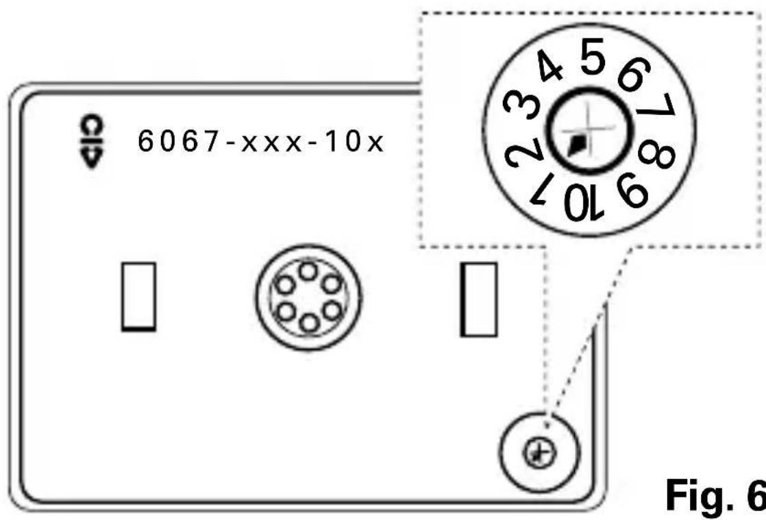
text_image
6067-xxx-10x Fig. 6When setting the address, take into account the "IR receiving range" (see Fig 3 and Fig. 4).
Operation

When the operating element is clipped on, Insert 6401U-102 automatically recognises which type of operating element is concerned.
a. Single-face Operation
Operation via Operating Element 6543-xxx-10x
- ON/OFF: Momentarily press/Hold down the face - Connected consumers will be switched ON or OFF
Extension operation via pushbuttons is identical.
b. Double-face Operation
Operation via Operating Element 6067-xxx-10x
- I: Momentarily press/hold down the upper face - Connected consumers will be switched ON.
• 0: Momentarily press/hold down the lower face - Connected consumers will be switched OFF.
The LED of the IR Operating Element blinks during transmission.
Operation

Extension operation via pushbuttons is identical to single-face operation.
NOTE
The command "dim darker" via the IR Remote Control does not trigger a switching operation in Insert Insert 6401 U-102. Please refer to, e.g., the Operating Instructions for the handheld IR Transmitter for further information regarding IR operation.
The last operation (also at extensions) always triggers the switching operation, even if, when the operating face is held down for a longer period, operation does not appear to have been completed.
c. Busch Remote Control, IR Operation
The MEMO memories M1 and M2 can be accessed via IR hand-held or wall-mounted transmitters - refer to the relevant operating instructions.
- Actuate ON: Relay Insert switches ON
- Actuate OFF: Relay Insert switches OFF
- Brighter: Relay Insert switches ON
- Darker: No function
Operation

- MEMO: - Select control state
- Store MEMO
- Invoke MEMO 1 or 2
- ALL OFF: Relay Insert switches OFF
d. Operation with FM Sensors
After the supply voltage has been interrupted, or after connection to the supply system, irrespective of the degree of brightness measured, the Insert 6401U-102 switches connected consumers on again
- for approx. 80 seconds in the case of FM Sensors 6810-xxx-10x and, in the case of FM Sensors 6800-xxx-10x(M),
- for the time set (at least 1 minute with time settings of < 1 minute, with the exception of the short-time impulse ∠).
Operation

e. Extension Operation with FM Sensors
This extension operation is possible by means of:
- activation via an NO pushbutton,
- or Extension Insert 6805 U.
Passive Extension Operation via Pushbutton
The function effected via the NO pushbutton causes the connected consumers to be switched on
- irrespective of the degree of brightness measured
- for approx. 80 seconds in the case of FM Sensors 6810-xxx-10x and, in the case of FM Sensors 6800-xxx-10x(M),
- for the time set on the FM Sensor (even with time settings of less than 1 minute).
NOTE:
- In the case of extension operation via NO pushbutton, the maximum length of the extension line must not exceed 100 m.
- Use only pushbuttons without parallel-contact illumination.
Operation

- To prevent disturbances as a result of ripple voltage, the switched line must be laid separately to the extension line.
- Switching off is not possible via the extension.
- Repeated actuation when the lighting is switched on causes the set OFF delay to "restart".
Active Extension Operation with Insert 6805 U and FM Sensors:
Since the master and the extension each have a separate setting for the dusk value, the actual brightness conditions at the installation site can be individually taken into account.
The effective overtravel time is calculated by adding the times of the master and extension together. When used in conjunction with FM Sensors 6800-xxx-10x(M), it is recommendable to operate the extensions with the time-setting short-time impulse ∠ if the times set at the master should be adhered to as precisely as possible.
Operation

NOTE:
For further information, please refer to the relevant Operating Instructions.
f. Operation with Timer Operating Element 6412-10x
Please follow the relevant Operating Instructions.
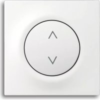
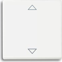
The lighting can be switched on and off via the two pushbuttons ▲▼.
Extension operation via pushbuttons is identical.
g. Operation with Presence Detector 6813
Please follow the relevant Operating Instructions.
With extension operation via pushbuttons, the lighting can be switched on and off irrespective of the brightness.
The active extension 6805 U, equipped with a presence detector, causes, as sensor, detected movement to be transmitted to the master (6401U-102). Depending on the brightness, the master decides whether the lighting is to be/to remain switched on.
Fault Elimination

Diagnosis Cause/Remedy
Load does not switch - Check extensions via extension: - Reduce ripple voltage > 100 V
Load does not generally - Change defective load switch: - Replace device if necessary
Load switches on - Reduce ripple voltage > 100 V independently: - Remedy incorrectly laid line (see chapter "Installation")
IR receiver/consumer - IR receiver is not within does not react: IR transmission range
- IR transmission range is covered (objects, hands or bodies)
- Battery is dead
LED of the - Remove extraneous IR light IR C-disc is OFF: source
- Apply supply voltage - Disconnect supply voltage for approx. 5 seconds
Fault Elimination

Diagnosis Cause/Remedy
LED of the IR C-disc - Remove extraneous IR light blinks continuously: source
LED of the IR C-disc - Check IR signal reception does not blink when - Replace battery of the IR a signal is transmitted: handheld, or wall-mounted, transmitter
- IR transmission range has been exceeded
Relay Insert cannot be - Remove illuminating device operated via the from pushbutton extension extension:
Light is not on: - Replace defective lamp
- Replace/re-energize line-side fuse
- Repair broken incoming line
Warranty for final user

Busch-Jaeger devices have been manufactured according to the latest techniques and subjected to quality control. If, how-ever, a defect should occur, Busch-Jaeger Elektro GmbH (hereinafter referred to as Busch-Jaeger) provides a warranty to the following extent:
Period of warranty:
The period of warranty covers 12 months from the date of purchase of the device by the final user. It expires 18 months after the date of manufacture at the latest.
Scope of warranty:
All components of the device which are verifiably unserviceable or the serviceability of which is considerably impaired as a result of a circumstance prior to the transfer of risk, in particular as a result of defective design, poor material or faulty workmanship, shall, at the discretion of Busch-Jaeger, either be repaired in the works of same or remanufactured free of charge. The supplier must be informed in writing, without undue delay, that such defects have been determined.
Exclusion clause:
Our warranty does not cover natural wear or damage during transport. Moreover, damages on account of not
Warranty for final user

following the instructions concerning installation and un-professional installation of the device are not covered by our warranty. Busch-Jaeger must be given enough time and opportunity to remedy the fault. There is no warranty for any damage arising from inappropriate modifications or repair. This also applies to all spare parts.
Busch-Jaeger shall not be liable for any damage which has not occurred to the delivery item itself, in particular, any indirect, consequential or pecuniary damage.
Statute of limitation:
If Busch-Jaeger should not accept complaints made in time, the right of the complainant to claim damages on account of a faulty delivery is nullified in all cases six months from the date of the first complaint.
Return of goods:
In order to safeguard the rights arising from this express warranty, in the case of a warranty claim, the device, together with the completed warranty certificate and a brief description of the defect which is the subject of complaint, is to be sent to the distributor responsible or to the Busch-Jaeger Service Center.
Fig. 1

text_image
6067-xxx-10x Fig. 6Fig. 6
6810-xxx-10x 0,8 - 1,2 m under 6800-xxx-10x
6800-7x-10xM 0,8 - 1,2 m (trappehus) over
2,0 - 2,5 m (romovervåkn.) over
6800-2xx-10xM 0,8 - 1,2 m (trappehus) under
2,0 - 2,5 m (romovervåkn.) under
Montering

text_image
6067-xxx-10x Fig. 6Vær oppmerksom på "IR-mottaksområde" ved adressering (se Fig. 3 og Fig. 4).
Betjening

Innsats 6401 U-102 registrerer automatisk hvilket betjening-selement det dreieier seg om, när det settes på plass.
a. Enkeltvirkende impulsbryter
Betjening via element 6543-xxx-10x
- PÅ/AV: Trykk/Hold betjeningstasten
Betjening via IR-element 6067-xxx-10x