2CKA006430A0385 - Smart Home Busch-Jaeger - Free user manual and instructions
Find the device manual for free 2CKA006430A0385 Busch-Jaeger in PDF.
| Title | Description |
|---|---|
| Product Type | Smart Home Controller |
| Compatibility | Compatible with Busch-Jaeger smart home systems |
| Features | Control of lighting, roller shutters, and connected devices |
| Installation | Flush-mounted installation in walls, requires electrical wiring |
| Power Supply | Standard power supply, check local specifications |
| Dimensions | Specific dimensions not provided |
| Materials | High-quality plastic, elegant finish |
| Maintenance | Regular cleaning with a soft cloth, no abrasive products |
| Safety | Complies with current electrical safety standards |
| Warranty | Manufacturer warranty, duration to be confirmed with retailer |
| Additional Information | Refer to the user manual for detailed instructions |
Frequently Asked Questions - 2CKA006430A0385 Busch-Jaeger
User questions about 2CKA006430A0385 Busch-Jaeger
0 question about this device. Answer the ones you know or ask your own.
Ask a new question about this device
Download the instructions for your Smart Home in PDF format for free! Find your manual 2CKA006430A0385 - Busch-Jaeger and take your electronic device back in hand. On this page are published all the documents necessary for the use of your device. 2CKA006430A0385 by Busch-Jaeger.
USER MANUAL 2CKA006430A0385 Busch-Jaeger
D F G B N L I E P L R U S
6800-xxx-102(M)/103M/104(M)-500
- Fig. 1: Wiring example (Normal Mode) 62
- Fig. 2: Wiring example (Modes of Operation) 63
- Fig. 3 and 4: IR Receiving Range 64
1. Overview
- Fields of Application 66
- Possible Combinations 66
2. Important Information
- Documentation 68
-Waste Disposal 68
3. Technical Data 69
4. Installation
- Installation 70
- ... in conjunction with Operating Elements .... 70
- ... in conjunction with Präsenz 6813-xxx-500 ....... 71
- ... in conjunction with Extensions 71
- ... in conjunction with Flush-mounted (FM) Sensors 73
- Addressing the IR Operating Element/Fig. 5 ......... 74
- Modes of Operation 76
Table of Contents

5. Operation
- ... via Operating Element 6430-… /6543-… 78
- ... via IR Operating Element 6066... /6067... 78
- .. via Busch Remote Control 80
- .. via Sensors 81
- Extension Operation via Sensors 81
- ... Passive Extension Operation 82
-
... Active Extension Operation 83
-
.. via Prasenz 6813-xxx-500 84
-
Supply Voltage Interruption 85
- Fault Elimination 86

Fig. 1/Normal Mode
Universal Series Insert in Operating Mode 1 (see Chapter 4.4) in individual mode with pushbutton control
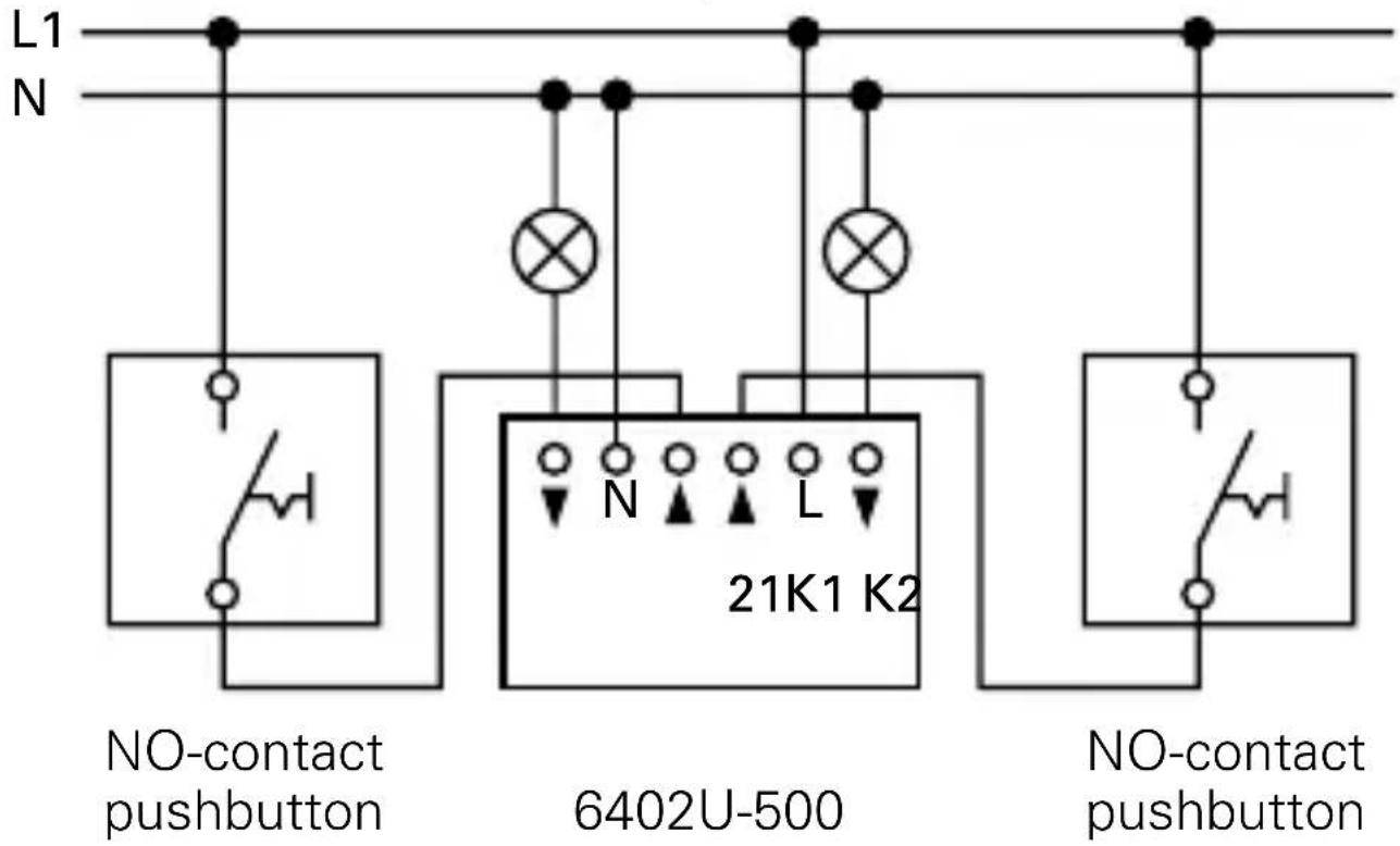
NOTE
In the case of illuminated pushbuttons, only pushbuttons with a separate N terminal can be used. Illumination via parallel contacts is not permissible!

Fig. 2
Universal Series Insert in Operating Mode 2 (see Chapter 4.4)
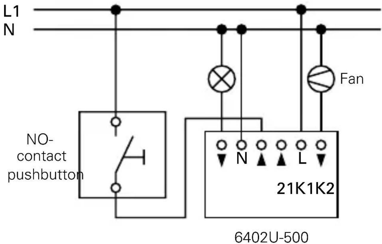

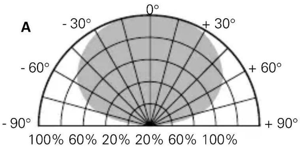
Fig. 3
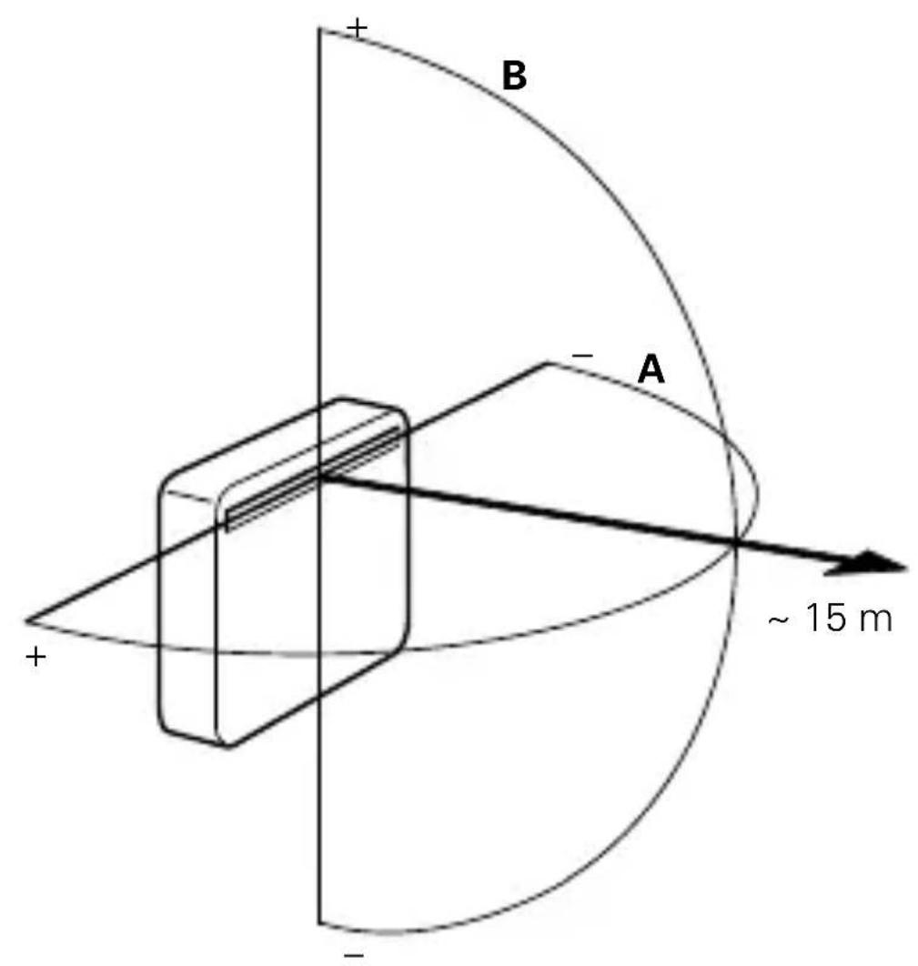
IR Receiving Range

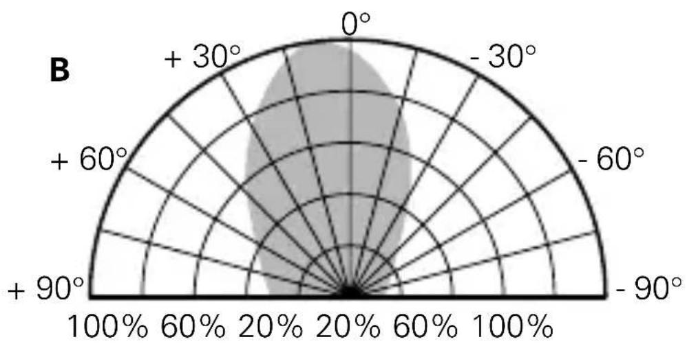
Fig. 4
IR Receiving Range
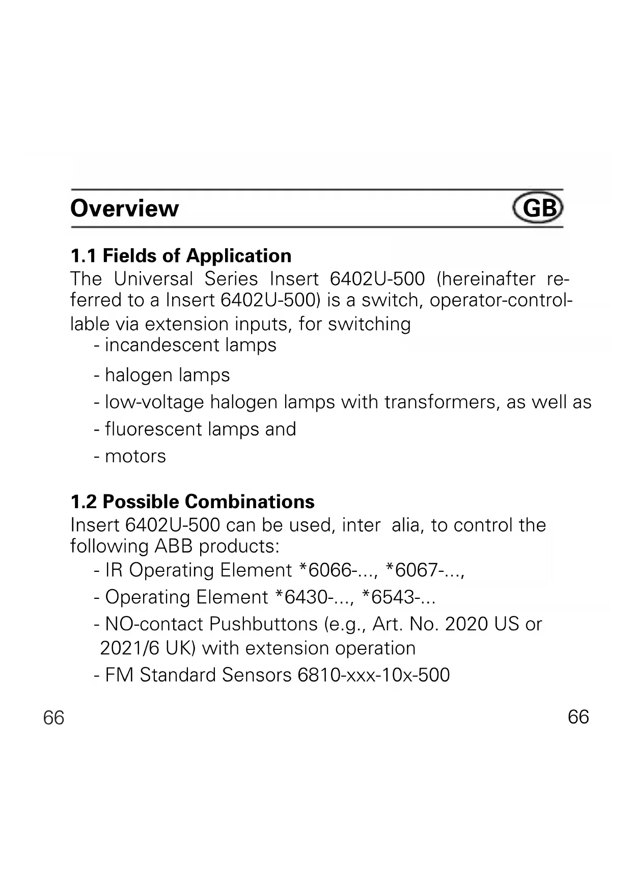
Overview

1.1 Fields of Application
The Universal Series Insert 6402U-500 (hereinafter referred to a Insert 6402U-500) is a switch, operator-controllable via extension inputs, for switching
- incandescent lamps
- halogen lamps
- low-voltage halogen lamps with transformers, as well as
- fluorescent lamps and
- motors
1.2 Possible Combinations
Insert 6402U-500 can be used, inter alia, to control the following ABB products:
- IR Operating Element 6066-, 6067-,
- Operating Element 6430-, 6543-...
- NO-contact Pushbuttons (e.g., Art. No. 2020 US or 2021/6 UK) with extension operation
- FM Standard Sensors 6810-xxx-10x-500
Overview

- FM Comfort Sensors 6800-xxx-102(M)/103M/104(M)-500
-
Busch Watchdog® Präsenz 6813-xxx-500
-
The type of operating element chosen depends only on the appropriate lettering. Operation is always identical.
Important Information

CAUTION
Work on the 230 V supply system may only be carried out by authorized electricians.
2.1 Documentation
Both the Busch Watchdog Standard (Art. No.6810-xxx-10x-500) and Comfort Sensors (Art. No. 6810-xxx-10x-500), as well as "FM Sensors" are described in these Operating Instructions. Always pay attention to the correct type assignment in the description.
The type description is on the back of each device.
2.2 Waste Disposal
All packaging materials and devices from ABB are provided with identification and test marks to ensure appropriate and proper disposal. Dispose of packaging materials, as well as electrical devices and their electronic components, via appropriately authorized collection centres or wasted disposal operations.
Technical Data

Supply voltage: 230 ~V ± 10% , 50 Hz
Wattage: < 1.5 W
Max. switching voltage: 250 ~V
Max. switched current (for all outputs together): 2300 W/VA, 10 AX
Max. ripple voltage 100 V with 100 m line at the extension: length
No. of pushbuttons: unlimited
Type of protection: IP 20
Operating temperature: 0 to +35 °C
Installation
GB
Switch off supply voltage!
4.1 Installation of Insert 6402U-500
Insert 6402U-500 is installed in a conventional FM device box in accordance with DIN 49073, Part 1.
4.2.1 Installation in conjunction with Operating Elements
Installation Site (see Fig. 3 and 4)
When used in conjunction with IR Operating Elements 6066- ... and 6067- ... , the installation site should be within the specified values for the IR reception range. In this context, please note that the IR reception range can change due to ambient light (e.g., solar radiation, lighting).
To fit the Operating Element
Prior to fitting IR Operating Elements 6066-… and 6067-…, set the desired address. Clip the operating element onto Insert 6402U-500.
To remove the Operating Element
Use the notches on the left and right to lift off the operating element.
Installation
GB
4.2.2 Installation in conjunction with the Busch Watchdog Prasenz 6813-xxx-500
Installation Site
When used in conjunction with Presence Detector 6813-xxx-500, only ceiling installation is of advantage. If possible, Presence Detector 6813-xxx-500 should be installed directly above the respective workplace.
To fit Presence Detector 6813-xxx-500
For installation and testing mode, it is recommendable to use the adapter provided. Subsequently, Presence Detector 6813-xxx-500 is firmly clipped onto Insert 6402U-500.
To remove Presence Detector 6813-xxx-500
Pull Presence Detector 6813-xxx-500 off Insert 6402U-500 by means of the ring on the housing.
4.2.3 Installation in conjunction with Extensions
Insert 6402U-500 can be operated via extensions. In this context, the following must be taken into account:
Installation

- The maximum line length depends on the maximum permissible ripple voltage at the extension inputs. However, the ripple voltage must not exceed 100 ~V (in practice, this corresponds to a line length of at least 100 ~m ).
The following can be used as an extension:
- NO-contact pushbutton (e.g., 2020 US or 2021/6 UK)
CAUTION
Illumination of the pushbutton extension parallel to the switching contact is not permissible; use pushbuttons with separate "N" terminal.
To ensure optimum operation,lay switched lines separately to the extension lines.
Installation

4.2.4 ... in conjunction with FM Sensors/Presence Detectors
To ensure optimum operation of the FM sensors, refer to the following table.
| Type of FM Sensor/Presence Detector | Installation HeightField of Application | Installation loca-tion of the con-necting screws |
| 6810-xxx-10x-500 06800-xxx-10x-500 | 8 - 1,2 m bottom | |
| 6800-7x-10xM-500 | 0,8 - 1,2 m(staircase) top | |
| 2,0 - 2,5 m(room monitoring) top | ||
| 6800-2xx-10xM-500 0 | 8 - 1,2 m(staircase) bottom | |
| 2,0 - 2,5 m(room monitoring) bottom | ||
| 6813-xxx-500 depencds onceiling height as desired | ||
Installation/Fig. 5

For further information regarding the installation height, setting of the FM sensors, etc., please refer to the appurtenant Operating Instructions.
4.3 Addressing the IR Operating Element
The address of the IR Operating Elements 6066... and 6067... is set ex Works to the number 1. The address can be changed via the rotary address disc on the back of the operating element.
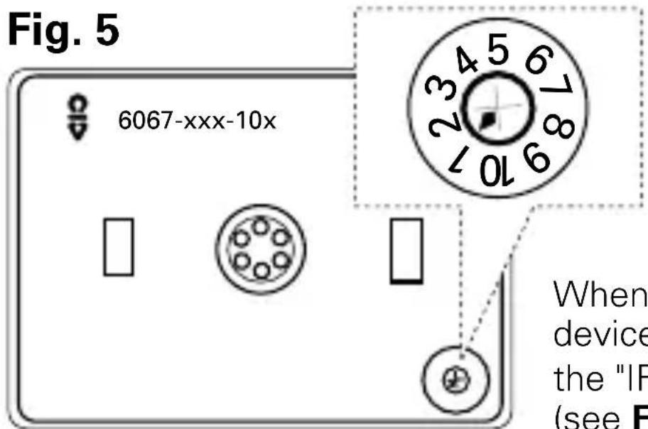
When addressing the device, pay attention to the "IR reception range" (see Fig. 3 and Fig. 4)
Installation

The address set applies in respect of output K1; the next highest address automatically applies in respect of the second output, K2.
| Setting the outputs (6402U-500) | ||
| 6066-/6067-xxx K1 K2 6010-25 | ||
| 1 1 2 | white | |
| 2 2 3 | ||
| ……… | ||
| 5 5 1 | ||
| 6 6 7 | blue | |
| 7 7 8 | ||
| ……… | ||
| 10 10 6 | ||
Installation

4.4 Modes of Operation
Set the operating mode desired prior to fitting the 1 × 5 operating element on the potentiometer.
Operating Mode 1 (Normal Mode):
Separate switching of both outputs via the Operating Elements 6430-..., 6543-..., 6066-... and 6067-...
Operating Modes 2 - 5:
| Operating Output K1 ON Output Mode Output K2 Output K2 | K1 OFF | |
| 2 ON after 10 s OFF after 5 min | ||
| 3 ON after 2 min OFF after 5 min | ||
| 4 ON after 2 min OFF after 10 min | ||
| 5 ON after 2 min OFF after * | min | |
- as long as Output K1 is switched on, however, a maximum of 21 minutes.
Installation

NOTE
Output K2 is independent of Output K1, except in Operating Mode 1 (left limit stop, see Fig. 1 and 2). If Output K1 is switched off again during the switch-on delay period of Output K2, Output K2 is not switched on.
Operation

When the operating element is clipped on, Insert 6402U-500 automatically recognizes the type of operating element concerned.
5.1 Mechanical Operating Element 6430-../6543-...
Single-surface operation in Operating Modes 2 - 5
- Surface: Press/hold down
- Output K1 ON/OFF
Output K2 switches according to the operating mode selected (see Chapter 4.4)
5.2 IR Operating Element 6066-../6067-
a. Operation in Operating Mode 1
- Upper surface: Output K1 is switched over
- Lower surface: Output K2 is switched over
b. Two-surface operation in Operating Modes 2 - 5
- Upper surface: Press/hold down
- Output K1 is switched ON
- Lower surface: Press/hold down
- Output K1 is switched OFF
Operation

Output K2 switches according to the operating mode selected (see Chapter 4.4)
NOTE
The command "Dim down" via the IR Remote Control does not initiate a switching operation. For further information regarding IR control, please refer, e.g., to the Operating Instructions of the IR Hand-held Transmitter.
The last operation in each case (also at extensions) initiates the switching operation, even if, when the operating surface is held down longer, the operation does not appear to have been completed.
Operation

5.3 Busch Remote Control IR Operation
a. Operating Mode 1:
The MEMO memories M1 and M2 are accessed via the IR Hand-held, or Wall-mounted Transmitter - see appurtenant Operating Instructions.
- Switch ON: Insert 6402U-500 switches ON *
- Switch OFF: Insert 6402U-500 switches OFF *
- Brighter: Insert 6402U-500 switches ON *
- Darker: No operation
-
MEMO: - Create control state **
-
Save MEMO
-
Invoke MEMO 1 or 2
-
ALL OFF: Insert 6402U-500 switches OFF **
-
Depending on which pair of pushbuttons on the IR Handheld Transmitter is operated, Output K1 or K2 is switched. ** Applies in respect of both Output K1 and K2.
b. Operating Modes 2 - 5:
In these operating modes, only Output K1 is controlled. Output K2 switches according to the Table on page 76.
Operation

5.4 Operation via Sensors (Operating Modes 2 - 5)
After interruption of the supply voltage or connection to the supply, Insert 6402U-500 switches the connected consumers connected of Output K1 on again
-
irrespective of the brightness measured
-
for 80 seconds when FM Sensors 6810-xxx-10x-500 are used,
-
for the selected period (at least 1 minute with time-setting < 1 minute) (with the exception of the short-time impulse ).
5.5 Extension Operation via Sensors (Operating Modes 2 - 5)
This type of extension operation only has an effect on Output K1; Output K2 switches according to the operating mode set (s. Chapter 4.4). Extension operation is possible by
- activating via the NO-contact pushbutton, or
- Extension Insert 6805U-500.
Operation

Passive Extension Operation via Pushbutton
The operation effected via the NO-contact pushbutton causes the connected consumers
a. to be switched ON and OFF in Operating Mode 1
b. in Operating Modes 2 - 5,
-
irrespective of the brightness measured (Output K1),
-
to be switched on for approx. 80 seconds when FM Sensors 6810-xxx-10x-500 are used
-
to be switched on for the time set on the FM sensor when FM Sensors 6800-xxx-10x(M)-500 are used (even with time settings of less than 1 minute)
-
to be switched over (ON > OFF > ON > ...) when the Busch Watchdog® Präsenz 6813-xxx-500 is used.
NOTE
- In the case of extension operation via NO-contact pushbuttons, the maximum length of the extension line must not exceed 100m .
- Use only pushbuttons without contact-parallel illumination.
Operation

- In order to prevent faults as a result of ripple voltage, the switched line is to be laid separate to the extension line.
Active Extension Operation via 6805U-500 and FM Sensors (Operating Modes 2 - 5)
Since the master and extension each have a separate dusk-value setting, the current brightness conditions at the installation site must be taken into account individually.
The effective reset time is determined by adding the times at the master and extension. In conjunction with UP Sensors 6810-xxx-10x(M)-500, it is recommendable to operate the extensions with the time setting short-time impulse ) if the times set on the master are to be kept virtually precisely.
NOTE
For further information, please refer to the appurtenant Operating Instructions.
Operation

Please follow the appurtenant Operating Instructions.
With extension operation via pushbuttons, the lighting can be switched on and off irrespective of the brightness.
Active Extension 6805U-500, with a presence detector as sensor, ensures that the movements detected are transmitted to the master (Insert 6402U-500 and 6813-xxx-500).
The master, Presence Detector 6813-xxx-500 decides, irrespective of the brightness, whether the lighting is to be/ remain switched on.
Supply Voltage Interruption

6. Supply Voltage Interruption
In conjunction with the Operating Elements 6430-..., 6543-..., 6066-... and 6067-..., in case of a supply voltage interruption < 200 ms, the control state is restored.
In case of a supply voltage interruption >200 ms, the old state will be restored, or both outputs are OFF, when the supply voltage is restored.
In conjunction with sensors, Insert 6402U-500 behaves as described in Chapter 5.4.
Fault Elimination

Diagnosis Cause/Remedy
Load does not switch - Check extensions via extension: - Ripple voltage >100 V, reduce
Load does not generally - Defective load, replace switch: - Replace device if necessary Load switches on - Ripple voltage >100 V, automatically: reduce
- Line(s) laid incorrectly, remedy (s. chapter "Installation")
IR Receiver/Consumer - IR Receiver is not within the does not react: IR transmission range
- IR transmission range covered (objects, hands, or body)
- Transmitter battery flat
LED of the - Eliminate IR ambient light IR C-disc off: source
- Apply supply voltage
- Switch off supply voltage for approx. 5 seconds
Fault Elimination

Diagnosis Cause/Remedy
LED of the IR C-disc - Eliminate IR ambient light blinks continuously: source
LED of the IR C-disc - Check IR signal reception does not blink upon - Replace battery of IR Hand-transmitting signal: held, or Wall-mounted
Transmitter
- IR transmission range exceeded
Insert 6402U-500 - Remove lighting from the cannot be controlled pushbutton extension via the extension:
No remote control - Operating Element is jammed possible:
Light is not on: - Replace defective lamp
- Replace upstream fuse/ switch on again
- Repair broken feeder
- Check operating mode/change if necessary (s. chapter 4.4)
Inhoudsopgave
NL
Afbeeldingen
BCEX BbIXoIOB: 2300 Bt/BA, 10 A
MaKcImaJIbHoe HaVeIeHHoe
HanpЯЖeHne Ha
KolnueCTBO KHONOK: He orpaHnueHo
BnДЗaцNTы:IP20
- 3aMbIkaHou KhoNkU (HaNP. 2020 US nnn 2021/6 UK).
BHIMAHNE!
Ha notehcnoMeTppe XeJaembI peXIM pa60Tbl.
PexnM pa60tbl 1 (HopMaJIbHbI)
Pexnmbi pa60tbi 2-5:
Pexim BbIXoJ K1 noKJIooH, BbIXoJ K1 oTKJIooH, pa60TbI BbIXoJ K2: BbIXoJ K2:
2 noKJIouaETc8 OTKJIouaETc8 yepe3 10 cek. yepe3 5 mH.
3 noiklouaetcnoKlouaetcnyepe3 2 mH. yepe3 5 mH.
4 noKIOUaETc8 OTKIOUaETc8 uepe3 2 mH. uepe3 10 mH.
5 noKIOUaETc8 OTKIOUaETc8 uee3 2 MnH. uee3 * MnH.
MoHTaK

* - cTOLbKO BpeMeHn, cKoJIbKO BpeMeHn IOdKJIoueH BbIXoI K1, B IIO6OM cIyuae MaKcImaJIbHo uepe3 21 MInHyTu.
ПРИМЕЧАНЕ.
BbIXoJ K1 haxoIITcB 3aBnCmOCTN OT BbIXoJa K2, 3a NCKJIoueHHeM pa60TbIB peXnme 1 (KpaJHee JleBoe noloxHne noteHcnomeTpA, cm. Pnc. 1, 2).
Ecni BbIXoJ K1 B TeueHne BpeMeHn 3aepKKn nepeKJIoueHn CHOBa OTKJIouaETcR BbIXoJOM K2, T0 BbIXoJ K2 6OJIbIe He BKJIouaETcR.
Ynpablenne

YHnBepcaIbHbI cepHbI 6Jok 6402 U-500 npu yCTaHOBKe Ha Hero ynpaBIAUoJero 3JeMeHTa aBTOMaTnueckn paCNo3HaET KaKOrO Tnna 3TOT 3JeMeHT.
5.1 MexaHnueckn ynpabJIouoIy IeMeHT 6430-.../ 6543...
ynpaBJIeHne C NOMOoiIO OJIeMeHTa C OJHOI IOBepxHocTbIO B pexmMax pa6OTbl 2 - 5.
pa6o7aHaKaTbHaIOBepXHocTb/ NOBepxHOCTb ydepxNBaTb B HaKATOM IPOJKeHN, -BbIXoJ K1 BkIIOyaeTcra nIN BBIKIIOyaeTcra
BbIXoI K2 nepeKJIIOUaETcB B COOTBETCTBnC BbI6paHHbIM peXmOM pa60TbI (cM. pa3dE1 4.4)
5.2 Инфрак расьй плььт упаBLе_HЯ 6066-../6067-... a.ynpaBLeHneВpeЖиme pa6OTbI1.
- BépxHЯ NOBépxHocTb: - nepeKJIouaetcRy BbvXoJ K1.
- HIXHЯ NOBepxHOCTb: - NepeKJIIOuaETcR BbIXoJ K2.
Ynpablenne
RUS
6. упаьени С поюю зLEM enta C DByma NOBepxHocTamy B peXnme pa60tbi 2 - 5.
BepxHnHaXaTb Ha BepxHIOIO NOBepxHOCTb/ NOBepxHOCTb: yIepxNBAtB HnKaTOM NIOJKeHn, -BbIXoD K1 BkJIouaETcra.
- HNXHЯ HaKaTb Ha HNXHIOI NOBepXHOCTb/ NOBepXHOCTb: ydepxnBaTb B HaKaTOM NOLOKeHIn, - BbIXoJ K1 BblKJIIOuHaeTcJ.
BbIXoI K2 nepeKJIIOUaETcR B COOTBETCTBm C Bbl6paHHbIM peXnMOM pa60TbI (cm. n. 4.4)
ПОНМЕЧАНЕ.
Komanda "3aTeMHeHne", NOdaHHaC NOMOu HnΦpaKpachoro pYbTa ynpaBLeHna, YHNBepCaJIbHbIM cepiHbIM 6IokOM 6402 U-500 He BOCpHnHaMeTcra. POnDpo6HyIO INΦopMaUIO NO DInCTaHcNtOHHomy ynpaBHeHIO Bbl NaIdTe B INHcTpkyuNIO NO 3KcPlyaTaUcN K IpeHocHOMy INΦpaKpachOMy pYbTy ynpaBHeHna. KaJdoe nocJeDuOuCe DeIcTBNe ynpaBHeHna (n C NOMoBu DOIpONHITeNbHbIX yCTPOIcTB ynpaBHeHna)
Ynpablenne

BbI3bIBAeT cpa6aTbIBaHne, daJKe ecJI npN dJIInTeIbHOM yIepXaHn IOBePxAOCTN BbIKJIouaTeJI, yIpaBJIeHne Ka3aJIOc6 bI He 3aKOHuINOCb.
5.3. YnpaBleHne ot dNcTaHcNoHHoro IK nyIbTa ynpaBleHn.
a. peşknm pa60tbi 1:
Дocун К памати M1 ул m2 ocyusectBJIeTc C nOMOью HHФраКрachoro NepeHOCHO uIN HAcTeHNO rYIbTOB UnpaBJIeHn, CMOTPnte COOTBETCTBYIOUIne INHCTpyKcIIN NO 3KcPnyaTaUIn.
EIN - BKJIIOHTb: 6JOK 6402U-500 BKJIIOUaETcra
AUS - BBKJIIOHTb: 6Jok 6402U-500 BBIKJIIOuaeTcra
Heller-cBetnee: 6lok6402U-500 BkJIouaETcra*
Dunkler - TemHee: 6JOK He pearnpyeT.
- MEMO (namЯть): - yctaHOBNTb JKeJaEMOE
COCTOHNHe*
- 3aПиСаТь KOMаHДуВпamЯТь
- Bbl3BaTb пamЯТь M1 ул m2
ALLES AUS 6ko6402U-500
(Bcè OTKJIIOyeHo): OTKJIIOyaeTcra*
Ynpablenne

- He3aBnCmO OT 3amepeHHoN OcBeuHHOCTN
YcTpaHHe HEnCnPaBHOCTeI

He ropnt cBeToaNoD - yCTpaHnTb NOCTOpOHn
CBeToIIOvIK - yCTpaHnTb NOcTOPOHHN
YcTpaHHe HEnCnPaBHOCTeI

CBeT He ropnt: - 3aMeHnTb DepeKTHyIO Iamny,
- 3aMeHnTb IpeIoXpaHnTeIb IN CHOBa BkIIOuHTb Ipn6Op,
- yctaHTb 06pbB B npoBOdKe,
-Проберпь реки м рабтbl, пи Heo6xOДIMOCТСмEHNTb (сm.раздел 4.4).


238
238