6411 U101 - Smart Home Busch-Jaeger - Free user manual and instructions
Find the device manual for free 6411 U101 Busch-Jaeger in PDF.

| Product type | Flush-mounted blind/awning control |
| Brand | Busch-Jaeger |
| Model | 6411 U101 / 6411U/S-101 |
| Rated voltage | 230 V ~ ±10 %, 50 Hz |
| Max. inrush current | 3 A cos φ 0.5 |
| Power consumption | < 1 W |
| Shortest switching time | > 500 ms |
| Max. consumption per additional station input | < 3 mA |
| Sensor connection | SELV potential (protective extra-low voltage) |
| Ambient temperature range | 0 - +35 °C |
| Operating modes | Normal, Slat, Awning (with sensor), Central, Programming |
| Functions | Manual control, IR remote control, additional stations, brightness sensor, glass break detector |
| Mounting | In flush-mounted box depth 60 mm |
| Max. additional station line length | Approx. 100 m (ripple voltage < 100 V) |
| Safety | Disconnect power before mounting/dismounting; comply with DIN VDE 0100 |
| Maintenance | No special maintenance required |
Frequently Asked Questions - 6411 U101 Busch-Jaeger
User questions about 6411 U101 Busch-Jaeger
0 question about this device. Answer the ones you know or ask your own.
Ask a new question about this device
Download the instructions for your Smart Home in PDF format for free! Find your manual 6411 U101 - Busch-Jaeger and take your electronic device back in hand. On this page are published all the documents necessary for the use of your device. 6411 U101 by Busch-Jaeger.
USER MANUAL 6411 U101 Busch-Jaeger
Fields of application ENG 45
The 6411U-101 and 6411U/S-101 flush-mounted inserts are used to control
- shutters/louvres
- roller blinds
- sunblinds
- domelight covers, etc.
From now on, the term "shutter" is synonymous for the above listed applications in the operating instructions.
Both insets have various modes of operation, e.g. for simple movement of the shutter or for the adjustment of louvres (see the chapter on "Modes of operation").
Fields of application ENG 46
Special features of the type 6411U/S-101
The flush-type insert 6411U/S-101 has an additional terminal block to connect the brightness sensor and glass breakage detector and a knob for setting a threshold value for the brightness sensor. In this way either the brightness sensor 6414 and/or the glass breakage detector 6413 can be connected.
Fields of application ENG 47
Fig. 1
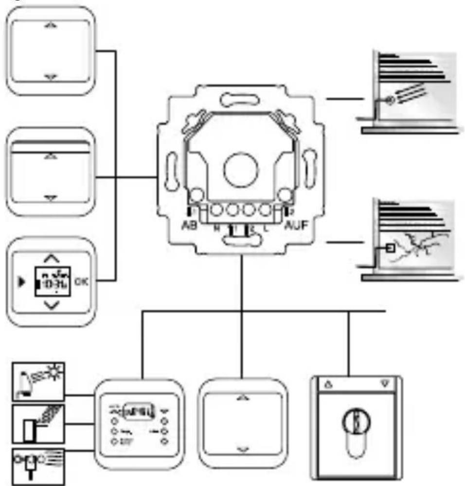
Possible combinations
Fields of application ENG 48
Fig. 2
6411 U/x-101
Stand-alone control
Fields of application ENG 49
Shutter control 1 controls the entire shutter motor bank. The shutters can also be moved individually by means of the other shutter control equipment.
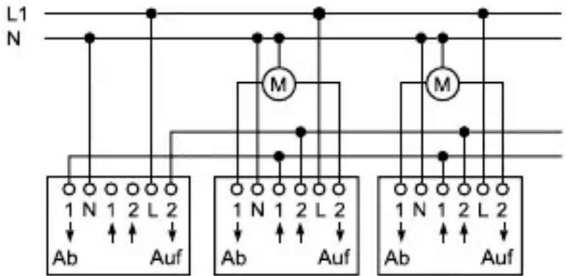
Fig. 3
Shutter control 1 Shutter control 2 Shutter control 3
UP inserts 6411U/x-101, 6411 U/x and 6410U-102 can be combined.
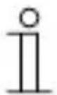
Fields of application ENG 50
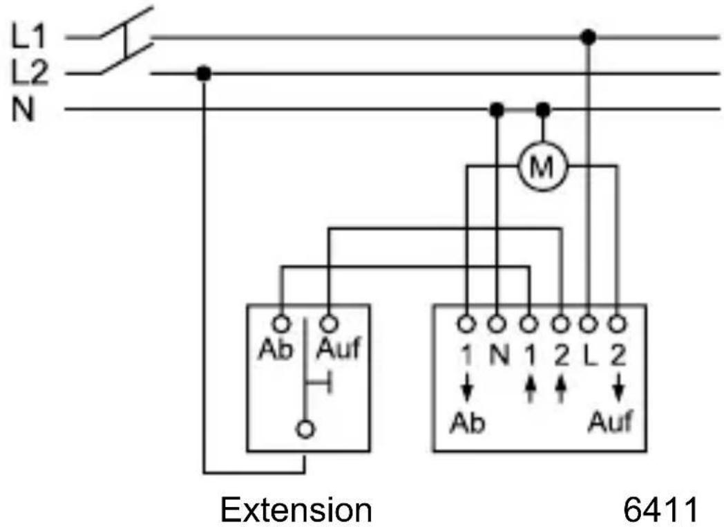
Fig. 4
Multi-phase operation
Important information ENG 51

Multi-phase operation is permissible only in Germany.
Work on the 230 V supply system may only be performed by specialist staff! De-energize mains power supply prior to installation and/or disassembly!
Failure to observe installation and operating instructions may result in fire and other hazards!
If multi-phase (2 phase) operation is desired for the control and function of the 6411 U/x-101 flush-mounted insert, the following requirements in accordance with DIN VDE 0100 are to be complied with without fail:
For the use in different differential current circuits, see circuit diagram in the Busch shutter control II user manual.
Only the same phase may be connected to the extension inputs terminals 1 and 2.
Important information ENG 52

CAUTION DANGER!
If different phases are permissible on the 6411U/x-101 flush-mounted insert, it must be ensured that all poles are disconnected in case of faults or when working on the unit.
This mode of operation is permissible only in Germany.
For use in different differential current circuits, see circuit diagram in the Busch shutter control II user manual.
For use via 3 phases, see circuit diagram in the Busch shutter control II user manual.

Ensure that
- the information of the respective shutter motor manufacturer is observed if you wish to connect up several motors in parallel.
- there are no people or objects in the radius of action of the shutters.
- the unit is off circuit when working on the flush-mounted insert.
Technical data ENG 53
Flush-mounted insert 6411U/x-101
Rated voltage: 230 ~V ± 10 % , 50 Hz
Max. switching current: 3 ~A 0,5
Power input: < 1 W
Cyclic duration factor of approx. 3 minutes relay (max. movement
operation time):
Shortest switch-over time: >500 ms
Max. current consumption < 3 mA
per extension input:
Sensor connection: SELV- potential, safety
extra-low voltage
Ambient temperature 0 - + 35^ C
range:
Overview of unit ENG 54
Fig. 5
Overview of unit
Overview of unit ENG 55
- Flush-mounted insert 6411U/S-101
- Supply system/extension connection
- Connection for shutter motor
- Adjustment knob for changing the mode of operation
-
- Detachable cover for shock-hazard protection (mounted ex works)
- Terminal block for connection of the sensor/detector
- Adjustment knob for setting the threshold for the brightness sensor
- Loop compartment for the sensor lead
- Connection to the operating element/connection dome
Items 6 and 7 are missing for the flush-type insert 6411U-101.
Modes of operation ENG 56
a. Changing the mode of operation
- Operating mode switch

Fig. 6

6411 U/S-101 6411 U-101
- Use a screwdriver to lift the control element over the frame.
- Rotate the adjustment knob to the desired mode of operation.
- Secure the operating element in the previous position. The new mode of operation is immediately active.
The mode of operation can be changed under voltage.
Modes of operation ENG 57
b. Modes of operation
Normal operation (N) = factory setting
- Application example: Moving the shutter UP/DOWN
- A brief actuation (tapping) of the operating area triggers a motion command that moves the shutter to the upper or lower limit position. If this is done again, the up/down motion is suspended.
- If the operating area is pressed continuously, the shutter moves up/down as long as this is done. If this is done for more than three minutes, the flush-type insert is switched off.
Adjustment of louvres (L)
- Application example: Moving the shutter UP/DOWN and slat adjustment in small steps.
- The brief actuation (tapping) of the operating area is identical to normal operation.
Modes of operation ENG 58
- If the operating area is pressed continuously, the shutter moves up/down – timed – as long as this is done. If this is done for more than three minutes, the flush-type insert is switched off.
Sun-shutter function (M)
- This operating mode open is only available for version 6411U/S-101 if a sun sensor is connected.
- The function is available with brightness sensor 6414.
- It has no effect without sun sensor or in the U-version (identical to normal operation).
- If the set brightness value is exceeded when this operating mode is activated, the shutter moves down for 3 min or a previously programmed motion time is carried out (and - if programmed - a return pulse).
- If the brightness value is no longer reached, the shutter is only moved back up again automatically if the operation time ensures that the sun is "in sight" of the sun sensor.
Modes of operation ENG 59
"Central" (Z)
- Application example: A shutter control flush-mounted insert is used as a central control unit for other shutters.
- Any actuation (short or long) of this central control unit is interpreted as a motion command (3 minutes) and put into effect. In this way, r it is ensured that all subordinate shutters move to the end position.
- Programmed down motion times are carried out for the extension units.
Programming (P)
- Application example: A move down command automatically moves the shutter downwards to a specified position and adjusts the louvres.
- After change-over to another mode of operation, the programmed motion time is only active if the shutter was moved upwards beforehand by a motion command (3 minutes) - only in this manner is it ensured that the desired position is approached.
Programming ENG 60
a. Procedure
- Activate this mode of operation as described in the chapter "Modes of operation" and re-attach the respective operating element.
- For practical purposes, the shutter is in its upper limit position. The shutter is moved downwards to the desired position by long actuation. The shutter can be stopped in between. The downward motion times are totalled up and stored.
- The return pulse (for slat adjustment, airing position for roller blinds) begins when the shutter moves UP for the first time. All subsequent motion times are added (UP motion) or subtracted (DOWN motion) and stored as an overall return pulse.
The max. return motion time is 25 s. The shutter is stopped if this time is not reached or exceeded.
- Before a return motion time is learned, a starting motion time of at least 10 seconds must have been learned beforehand.
Programming ENG 61
- Use a screwdriver to lift the control element off with the frame once more.
- Exit the "Programming" mode of operation and reset the originally desired mode of operation.
- Re-attach the operating element.

Programming can simplified, if an extension has been installed and is used to program the intermediate position.
Programming ENG 62
- If programming has been correctly carried out and the shutter is in the upper end position, the shutter moves downwards for the programmed downward motion time on receiving a move down command, pauses for 0.5 s and then moves upwards again for the time programmed for the return travel pulse.
- If the shutter is not in the upper end position, the move down command is executed without the programmed intermediate position. Shutter moves downwards for three minutes.
b. Clearing the programming
- With the control element removed, switch to "Programming" mode and then back to the previous operating mode.
Any existing programming is deleted.
Party/lock-out function ENG 63
- The party/lock-out function can only be activated in combination with the flush-type inserts 6411 U/x-101 and the control elements 6430-xx.
- This function excludes the flush-type insert from a group-controlled unit. That means that signals received via the extension unit inputs and on-site operation are ignored.
- The function can only be activated in the upper limit position (observe relay time of 3min.). Press the UP key to activate for >5 s. As acknowledgement, the shutter is moved down for two seconds and then back up to the upper limit position.
- The function is deactivated by pressing the DOWN key for >5 sec. The shutter moves down as acknowledgement. Deactivation is performed automatically after approx. 8 hours.
- Activating the party switch deactivates the sun protection, nightfall or sun-blind function. The party switch cannot be activated in Central and Programming operating modes.
Installation ENG 64
Switch off the supply voltage!
The unit is suitable for installation in conventional flushmounted boxes; we recommend installation in a branchcircuit switch box with an installation depth of 60 mm.
- When connecting, take note of the connection examples Fig. 2, 3 and 4.
Always check the direction of motion of the shutter.
a. Installation in conjunction with an operating element
Installation site
When combined with the 6066 IR operating element, the installation site should be within the stated IR receiving range (see Fig. 12 and 13). Take into account the fact that the IR receiving range can change as a result of outside light (e.g. solar radiation, lighting).
Installation ENG 65
If the use of a brightness sensor 6414/glass breakage detector 6413 is planned for the flush-type insert 6411U/S-101, the factory-set line length of approx. 2m must be taken into account.
Attaching the operating element
First set the desired address on the 6066 IR operating element (see chapter "Setting the address on the IR operating element").
- Attach the operating element onto the flush-mounted insert
Removing the operating element
- Use a screwdriver to lift the control element off with the frame.
Installation ENG 66
b. Installation in conjunction with extensions
The flush-mounted insert can be operated via extensions. Please note the following in this connection:
- The maximum line length depends on the maximum permissible ripple voltage at the extension inputs. However, the ripple voltage may not exceed 100 ~V (in practice this is equivalent to a minimum line length of 100 ~m ).
- In order to avoid faults caused by switching operations of the shutter drives, the motor and extension feeder circuits must be in separate cables and not laid in the immediate vicinity of each other (minimum distance 5 cm).
- When calculating the maximum number of units which can be operated in parallel in one fused circuit, the current consumption of the motors and the extension inputs and the power consumption of the UP inserts must be considered.
Operation ENG 67

The phase for extension inputs "1" and "2" must be the same and in the same circuit.
Operation of the shutter depends on the operating element used or the employment of sensors.
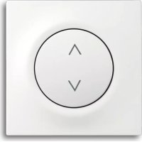
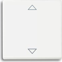
a. Operation via the 6430 operating element
Modes of operation N, E (see also chapter on "Modes of operation")
$$ \mathrm {U p} = \Delta : $$
Brief actuation (tapping) of the upper surface
- the shutter is moved into the upper end position.
Long actuation of the upper surface
- The shutter moves up as long as the key is pressed.
Operation ENG 68
Down = ∇: Brief actuation (tapping) of the lower surface
- the shutter is moved into the lower end position.
Long actuation of the lower surface
- The shutter moves down as long as the key is pressed.
Pressing it again stops the shutter motion.
Mode of operation L (see also chapter on "Modes of operation")
Brief actuation (tapping) has the same effect as in "normal operation". The shutter moves up to the corresponding limit position.
The long actuation can be used to change the slat angle in stages:
Up = : Long actuation of the upper surface, the shutter moves up, timed.
Down = ∇: Long actuation of the lower surface, the shutter moves down, timed.
Operation ENG 69
b. Operation via the 6066 IR operating element
Manual local operation and remote control via the IR handheld transmitter (Article no. 6010-25) are effected in the same way as in the actuation of the 6430 operating element.
The red LED on the 6066 IR operating element flashes in the transmit mode.
The upwards and downwards movement of the shutter can be stored in the M1 or M2 MEMO memories via the IR hand-held transmitter:
- Actuate the operating elements or the IR hand-held transmitter in the desired direction (UP/DOWN).
- Save the direction in M1 or M2. Press the Memo key beforehand.
Operation ENG 70
Clearing the MEMO memories
- Press the red EVERYTHING OFF button on the handheld transmitter
- Store the EVERYTHING OFF condition in M1 or M2. Memo key beforehand.

A louvre setting cannot be stored in a MEMO memory. The M1 and M2 MEMO memories can be accessed via IR hand-held or wall-mounted transmitters. You will find further information in the IR operating instructions.
Operation ENG 71
c. Operation via extensions
All types of signal generators are suitable that generate a 230V signal (no permanent signal) for extension units "1" and "2" (see fig. 1).
Operation depends on the respective range of function of the extension and on the selected mode of operation.
The flush-type insert interprets short voltage pulses as "short actuation (tapping)" and long voltage pulses as "long actuation".
Note about priorities of operation
The glass break detector has the highest priority. On triggering, the extension inputs are switched off. The shutter is moved downwards and can only be moved upwards again by local operation.
The extension unit input 2 for UP has second highest priority (wind alarm). If the input is powered, the shutter moves up and stays up as long as extension unit 2 is powered. All other operations have an equal ranking.
Brightness sensor ENG 72
The brightness sensor 6414 can only be used in conjunction with the 6411U/S-101 flush-mounted insert.
a. Function
Sunshade function
Can be combined with operating modes N, L.
Precondition for the faultless sun protection functionality is that the shutter can cross the sensor. If this is not ensured, then the sun-blind function (see operating mode M) must be used.
The sensor constantly measures the brightness and compares this value with the pre-set threshold value. If the threshold value is exceeded for more than 90 seconds, the shutter moves downwards.
As soon as the shutter obscures the sensor, the downward movement is stopped. The shutter is moved upwards again and stopped just above the sensor position.
The shutter is not moved into the upper end position again until the sensor measures a value which remains below the pre-set threshold value for more than 15 minutes, or an
Brightness sensor ENG 73
adjusting command is received from an operating element or an extension.
The sunshade function is interrupted by operation from an extension or operating element and manual operation is executed. The sunshade function is re-activated by a move up command (3 minutes motion time) or by the next light/ dark changeover. This takes place automatically through the outside brightness (dusk).
Dusk function only possible in conjunction with the timer operating element.
See separate operate instructions.
Brightness sensor ENG 74
b. Connection
Connection can be made under voltage.
Proceed as follows:
- If necessary, use a screwdriver to lift off the control element with the frame.
- Lift the cover (see Fig. 5, Pos. 5) off the flushmounted insert.
- Pull the terminal block (see Fig. 5, Pos. 6) off carefully upwards.
- Connect the brightness sensor.
Brightness sensor ENG 75

The polarity of the two cables must be respected:
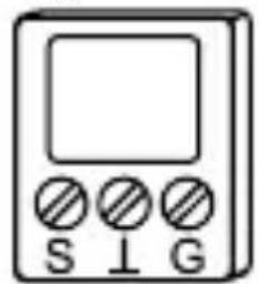
Fig. 9 S: Brightness
: Earth (white)
- Lay the sensor lead in the flush-mounted insert with a small loop for strain relief (see Fig. 5, Pos. 8).
Do not extend the sensor lead, since this could lead to impaired performance.

Please note that the shutter may be unexpectedly set in motion during adjustments/relocation of the brightness sensor.
Brightness sensor ENG 76
c. Setting (for operating element 6430 or 6066)
Please proceed as follows to set the threshold value for the brightness sensor irrespective of the current brightness:
- Ensure that the brightness sensor is attached at the planned position and uncovered.
- Change the position of the adjustment knob
- to the right if the sunshade function is to be actuated at a low brightness value,
- to the left if the sunshade function is only to be actuated at high brightness value.
Fig. 10
- Saving the current brightness as desired threshold value for the brightness sensor:
If the current brightness is to be stored as a threshold value, the adjustment knob (Fig. 5, Pos. 7) must first of all be turned to the minimum value (all the way to the right). Wait for a few seconds and then turn it to the
Brightness sensor ENG 77
maximum value (all the way to the left). In this manner, the programming of the brightness value is activated. The shutter moves upwards (if it is not already at the top) as an acknowledgement of this mode of operation. Next, slowly turn the adjustment knob (Fig. 5, Pos. 7) in the direction of decreasing brightness until the shutter moves downwards. The current brightness value is hereby stored. The sunshade function is immediately active.
d. Setting via timer operating element 6455, 6412-101
The sunshade and the dusk function are only adjustable in conjunction with a timer operating element. The threshold values are set via the timer operating element; the adjustment knob of the flush-mounted insert is then without function.
You will find further information about setting, etc. in the operating instructions for the timer operating element.
Glass break detector ENG 78
The glass break detector (Article. no. 6413) can only be used in conjunction with the 6411U/S-101 flush-mounted insert. This sensor is an optional accessory unit which can detect a bursting window pane.

Please note that the 6411U/S-101 flush-mounted insert in conjunction with the glass break detector is not suitable as a burglary/robbery protection device, since there is no sabotage security as prescribed in VdS.
a. Function
The flush-mounted insert automatically detects a connected glass break detector. If a pane of glass bursts, certain ultrasonic signals are produced which are evaluated by the detector. The detector sets off a move down command.
Glass break detector ENG 79

The shutter cannot be moved upwards via the brightness sensor, a timer signal or via an extension during or after triggering of the switching command. Once the shutter has moved down, it can only be moved up-wards again via the operating element of the flushmounted insert concerned.
When using a timer operating element, a separate signal, is sent to the operating element - you will find further information in the operating manual.
b. Connection
The connection can be made under voltage. Proceed as described in section b of the chapter on "Brightness sensor". The correct polarity of the twin stranded hook-up wire must only be respected with the brightness sensor.

You will find further information on the function and attachment in the operating manual of the glass break detector.
Addressing the IR control element
ENG 80
The address on the 6066 IR operating element is set ex works at number "1". You can change the address via the rotary addressing device on the back of the IR operating element. When setting the address, take into account the "IR receiving range" (Fig. 12 and 13).
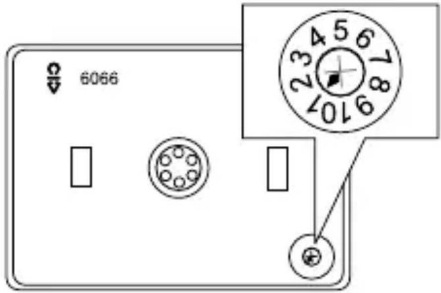
Fig. 11
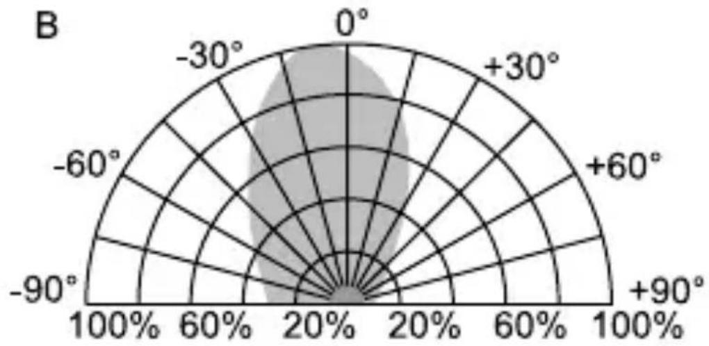
IR receiving range ENG 81
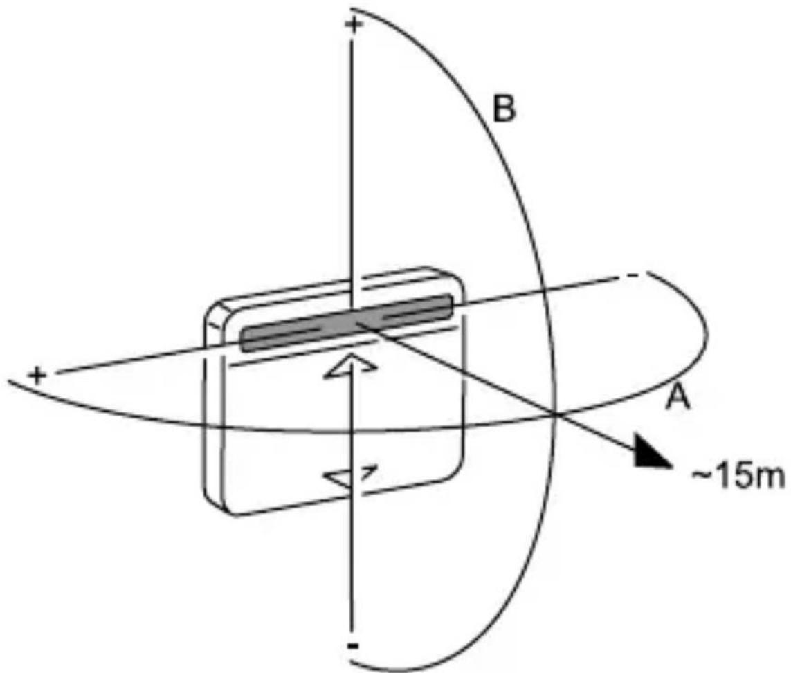
Fig. 12
IR receiving range ENG 82
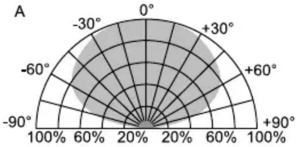
Fig. 13
Fault elimination ENG 83
Diagnosis
Shutters move variably (with group control):
Poss. cause/remedy
- change outputs on the 6411U/S 6411U/S-101
- exchange extension inputs on the 6411U/S-101
- Disconnect load line from control line
- Extension unit with higher priority is applied (e.g. wind alarm)
- Thermal motor protection active - wait a moment
- check mode of operation
- Party function is activated.
Fault elimination ENG 84
You will find further information about the use of a 6455 oder 6412- 101 timer operating element in the operating manual.
In addition, the following IR-specific faults can occur:
Diagnosis Poss. cause/remedy
LED on: - eliminate IR light from
external source
- apply supply voltage
LED flashes
- eliminate continuous signal
constantly:
from external source
LED does not flash
- keep within IR range of
with transmitted
transmission
signal:
- replace battery of the IR
handheld transmitter or
wallmounted transmitter

The IR receiving range can change as a result of outside light from external source (e.g. solar radiation, lighting).