
SCSL3NAAE - Air Conditioning MITSUBISHI - Free user manual and instructions
Find the device manual for free SCSL3NAAE MITSUBISHI in PDF.
| Product type | Centralized controller for air conditioning |
| Brand | Mitsubishi Heavy Industries |
| Model | SCSL3NAAE (SC-SL3NA-AE) |
| Display | Backlit LCD touch screen |
| Power supply | 220-240 V ~ 50/60 Hz (estimated) |
| Maximum number of blocks | 16 blocks |
| Maximum groups per block | 9 groups |
| Maximum units per group | 16 units |
| USB port | Yes (for data backup and transfer) |
| Main functions | On/Off control, mode (auto, cool, heat, dehumidify, fan), temperature, fan speed, louver direction, timer programming, remote controller lock, alarm history |
| Energy management | Consumption calculation (BE model only) |
| Available languages | Multilingual (FR, DE, EL, EN, ES, IT, NL, PT, RU, TR, ZH...) |
| Maintenance and cleaning | Clean with a soft dry cloth; for stubborn stains, use a damp cloth with diluted neutral detergent; do not use solvents or strong acids |
| Safety | Mandatory grounding; installation by professional; password for settings access; protection against electrostatic discharge |
| EMC class | Class A (may cause radio interference in residential environments) |
| Operating ambient temperature | 0 °C to 40 °C (estimated) |
| Ambient humidity | Up to 80% RH without condensation (estimated) |
Frequently Asked Questions - SCSL3NAAE MITSUBISHI
User questions about SCSL3NAAE MITSUBISHI
0 question about this device. Answer the ones you know or ask your own.
Ask a new question about this device
Download the instructions for your Air Conditioning in PDF format for free! Find your manual SCSL3NAAE - MITSUBISHI and take your electronic device back in hand. On this page are published all the documents necessary for the use of your device. SCSL3NAAE by MITSUBISHI.
USER MANUAL SCSL3NAAE MITSUBISHI
SC-SL3NA-BE (with Calculating Function)
MANUAL DEL PROPIETARIO
CONSOLA CENTRAL SC-SL3NA-AE, SC-SL3NA-BE
GEBRUKERSHANDLEIDING
CENTRALE CONSOLE SC-SL3NA-AE, SC-SL3NA-BE
MANUAL DO UTILIZADOR
CENTER CONSOLE SC-SL3NA-AE, SC-SL3NA-BE
O△HΓIEΣ XPHΞHΞ
KENTPIKH KONZOANA SC-SL3NA-AE, SC-SL3NA-BE
PYKOBODCTBO NO 3KcIyATAUIN
LIÉHTPAJIbHbI KOHTPOJIJIEP SC-SL3NA-AE, SC-SL3NA-BE
KULLANIM KILAVUZU
MERKEZI KOMSOL SC-SL3NA-AE, SC-SL3NA-BE
使用说明书
中央控制台SC-SL3NA-AE, SC-SL3NA-BE
ENGLISH
FRANCAIS
DEUTSCH
ITALIANO
ESPANOL
NEDERLANDS
PORTUGUES
EAAHNIKA
PYCCKM
TURKCE
中国语
C
This center console complies with EMC Directive 89/336/ EEC, 91/263/EEC, 92/31/EEC, 93/68/EEC, 2004/108/EC, LV Directive 2006/95/EC.
Cette console centrale est conforme à la Directive EMC: 89/336/EEC, 91/263/EEC, 92/31/EEC, 93/68/EEC, 2004/108/EC, LV Directive 2006/95/EC.
Esta consola central cumple con la directiva EMC: 89/336/ EEC, 91/263/EEC, 92/31/EEC, 93/68/EEC, 2004/108/EC, LV Directiva 2006/95/EC.
Deze centrale console voloet aan EMC Directive 89/336/ EEC, 91/263/EEC, 92/31/EEC, 93/68/EEC, 2004/108/EC, LV Directive 2006/95/EC.
Thank you very much for employing the Central Control of Mitsubishi Heavy Industries, Ltd.
Before using, read through this instruction manual for proper operation. After reading through it, carefully store it for future reference. If any trouble should occur during operation, it will be helpful. Also, read through the instruction manual which is attached to the air conditioner.
Table of contents
ENGLISH
■ Safety Precautions 2
■ Introduction Overview 4
Names and Functions of Parts 4
Blocks, Groups 4
Startup Screen 5
Quick Reference Chart for Operations 6
Main Menu 7
System Confi guration Screen 8
All Blocks Display 9
Icons 10
Changeover Confirmation Screen 10
Operation
Time & Date Setting 11
Group Defi nition 11
Block Definition 13
Group Operation Settings 15
Multiple Groups Operation Settings 18
Group Batch Operation 19
Schedule Settings 20
Viewing Detailed Unit Information 24
Calculating Settings (SC-SL3NA-BE only) 25
Convenient Functions
Entering Numbers and Characters 26
Function Settings 27
Corrections for Power Outages 28
Using USB Memory 28
Viewing Alarm History 30
System Information 30
Help 30
■ Maintenance 31
■ Shut Down 31
Troubleshooting 32
■ Installation 34
■ After Sales Service 34
PRECAUTIONS FOR WASTE DISPOSAL
Your central control may be marked with this symbol. It means that waste electrical and electronic equipment (WEEE as in directive 2002/96/EC) should not be mixed with general household waste. Central control should be treated at an authorized treatment facility for re-use, recycling and recovery and not be disposed of in the municipal waste stream. Please contact the installer or local authority for more information.

This symbol printed in the batteries attached to your central control is information for end-users according to the EU directive 2006/66/EC article 20 annex II.
Batteries, at their end-of-life, should be disposed of separately from general household waste. If a chemical symbol is printed beneath the symbol shown above, this chemical symbol means that the batteries contain a heavy metal at a certain concentration. This will be indicated as follows:Hg:mercury(0.0005%), Cd:cadmium(0.002%), Pb:lead(0.004%)
Please, dispose of batteries correctly at your local community waste collection or the recycling center.
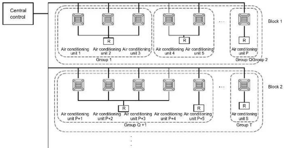
Safety Precautions
- Before starting to use the central control, read these "Safety precaution" carefully to ensure proper operation of the central control.
- The safety precautions are classified as “ DANGER” and “ CAUTION”. Precautions as shown in the column “ DANGER” indicate that improper handling could have serious consequences like death, serious injury, etc.
"CAUTION" might pose a serious problem, depending on the circumstances. Please observe these precautions with great care, since they are essential to your safety.
- Symbols which appear frequently in the text have the following meaning:

Strictly prohibited.

Observe instructions with great care.

Provide positive earthing.
- When you have read the instruction manual, please keep it near at hand for consultation. If someone else takes over as operator, make sure that the manual is also passed on to the new operator.
INSTALLATION PRECAUTIONS
DANGER
The central control must be installed by your dealer or a qualifi ed professional.

It is not advisable to install the central control yourself, as faulty handling may cause electric shock or fire.
CAUTION
- Make sure to perform grounding work. Depending on the place of
Installation, a leakage
breaker may be necessary.

Do not connect the ground wire to any gas pipes, water pipes, lightning conductors or a ground wire connected to telephones. Incomplete grounding may cause electric shock.

If a leakage breaker is not installed, electric shock may happen.
Consult your dealer.
OPERATION PRECAUTIONS
DANGER
If the central control is damaged with water due to a natural disaster such as a flood or a typhoon, consult your dealer.

Operating the central control under such conditions may lead to failure, electric shock and/or fire.
If the central control is under abnormal conditions, stop the operation, turn the power supply switch off and consult your dealer.

Continuing operating the central control under abnormal conditions may lead to failure, electric shock and/or fire.
CAUTION
Do not handle with wet hands. Do not pull the connecting wire.

This may cause an electric shock or failure.

If the core wire is disconnected, it could cause a short-circuit.
Do not wash the central control with water.

It may cause electric shock or failure.
Discharging static electricity through the unit could cause a break-down.
Before starting operation, touch a grounded metal object and discharge any static electricity.
If the screen freezes frequently, it is recommended to attach an antistatic sheet or similar object.
PRECAUTIONS FOR RELOCATION OR REPAIR
DANGER
Never modify or disassembling the central control. If it requires service, consult your dealer.

If servicing is inadequate, electric shock and/or fire may occur.
If it is required to relocate the central control, consult your dealer.

Improper installation of the central control may cause electric shock and/or fire.
The energy consumption calculated by this unit does not conform to OIML, and there are no guarantees concerning the results of the calculations.
This unit calculates only energy consumption distribution (gas, electric power). You need to calculate the air-conditioning rates.
Warning
This is a class A product. In a domestic environment this product may cause radio interference in which case the user may be required to take adequate measures. This unit is not a domestic use.
Introduction
Overview
Central controls are made to collectively control air conditioning indoor units. All the controls such as unit monitoring, operation, settings and scheduling can be done on the touch panel.
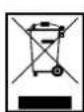
Names and Functions of Parts
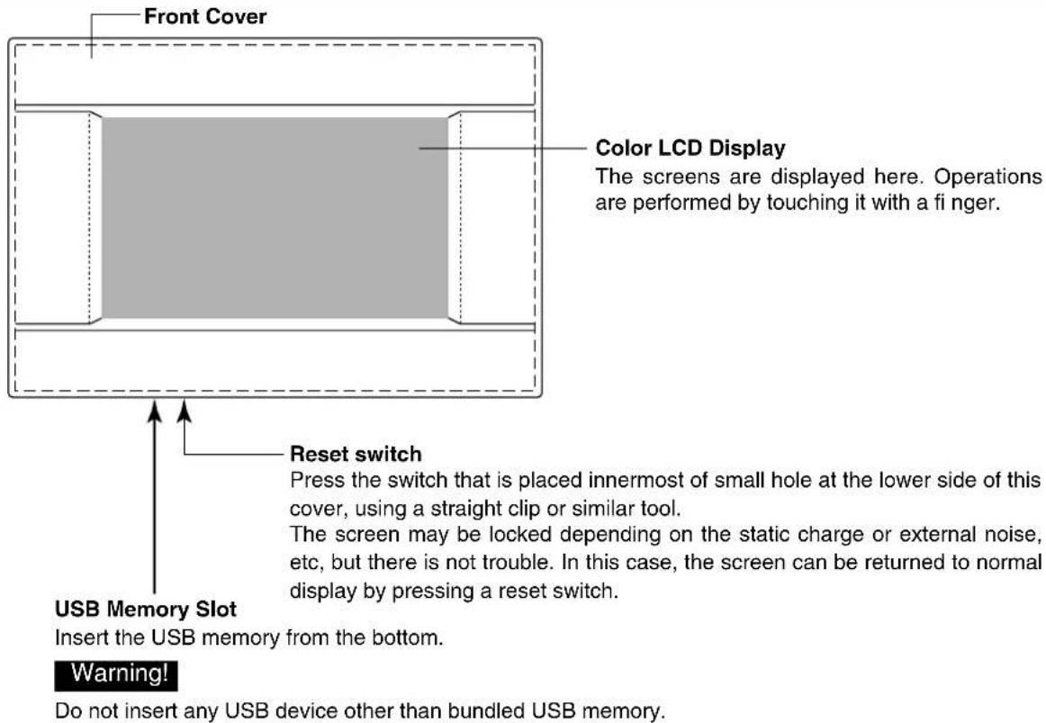
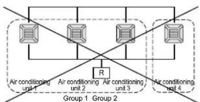
Blocks, Groups
[Example of Connections]
- A maximum of 16 air conditioning units can be set up in one group.
- Do not use one remote controller for different groups of air conditioning units.
- A maximum of 9 groups can be set up in one block.
- A maximum of 16 blocks can be set up.
R : Remote controller

Startup Screen
[Startup Screen]

[Information Screen]
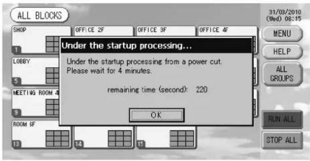
This screen is displayed at startup.
After a brief time, the following screen is displayed. It is not possible to do any setting when information screen is displayed.
- ALL GROUPS Display
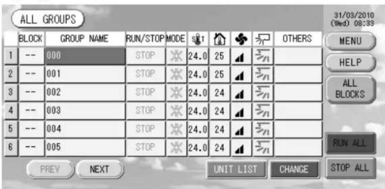
This display appears the first time the unit starts up or when block have not been registered. Make the initial settings in the following order.

Time & Date Setting page 11

Group Definition page 11

Block Definition page 13
- Once blocks are registered, it is very convenient because the status of all groups can be viewed on a single screen.
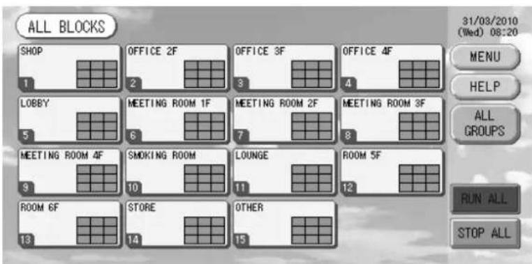
- ALL BLOCKS Display
When blocks have been registered, this display appears.
Note
It may take time for the settings to be read into the unit. Do not perform any operations until all the groups that have been set are displayed.
Quick Reference Chart for Operations
| Initial settings | Date & time Page 11 (Time & Date Setting) | |
| Groups Page 11 (Group Defi nition) | ||
| Blocks Page 13 (Block Defi nition) | ||
| Viewing status | All blocks Page 9 (All B ocks Display) | |
| All groups Page 17 (AL GROUPS screen) | ||
| Each group | Pages 15 & 17 (Group Operation Settings: GROUP(PANEL) & GROUP(List) screen) | |
| Each unit Page 24 (Viewing Detailed Unit Information) | ||
| Group operation Page 15 (Group Operation Settings) | ||
| Multiple groups operation Page 18 (Multiple Groups Operation Settings) | ||
| Batch operation Page 19 (Group Batch Operation) | ||
| Setting and checking schedules Page 20 (Schedule Settings) | ||
| Making calculating settings (SC-SL3NA-BE only) | Page 25 (Calculating Settings) | |
| Entering numbers and characters Page 26 (Enter ng Numbers and Characters) | ||
| Using convenient functions | Page 27 (Function Settings) | |
| Page 28 (Corrections for Power Outages) | ||
| Page 28 (Using USB Memory) | ||
| Page 30 (System Information) | ||
| Alarm history | Page 30 (Viewing Alarm History) | |
| Further Information | Page 30 (Help) | |
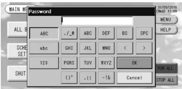
[Password Input Screen]
(*) Password
The password of SC-SL3NA-AE is SLNA.
- The password of SC-SL3NA-BE is SLNB.
It is not possible to change the password.
Main Menu
When the MENU button is pressed, the screen switches to the one shown below.
Please enter your password (*) after you press the SCHEDULE SETTING, SYSTEM CONFIG., SHUT DOWN, FUNCTION SETTING or IMPORT EXPORT button.
(*) Refer to page 6.
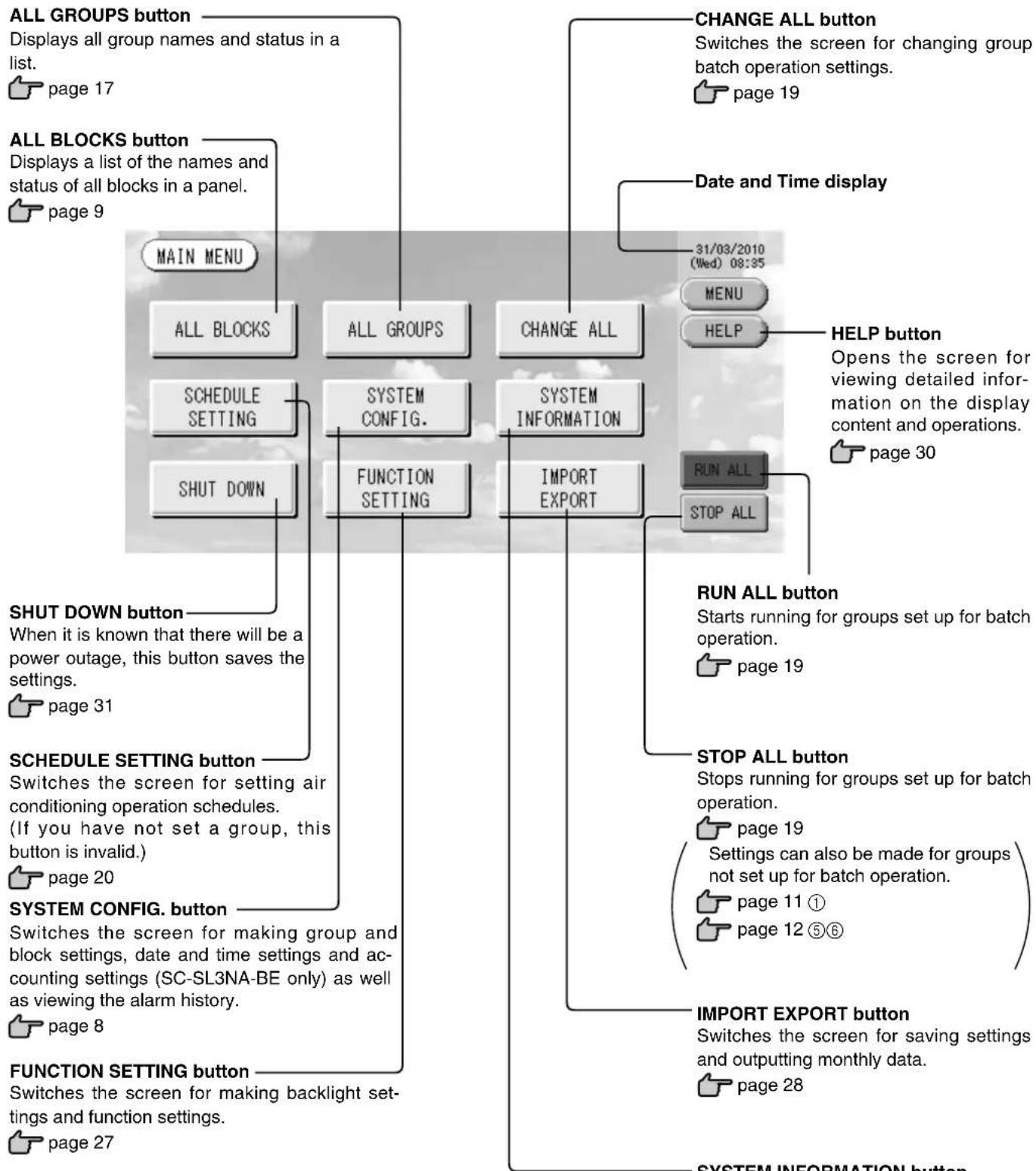
SYSTEM INFORMATION button
Displays the central control version number and number of units registered.
page 30
System Configuration Screen
This is displayed when the SYSTEM CONFIG. button is pressed on the Main Menu.

page 7
UNITDEFINITIONbutton
Switches the UNIT DEFINITION screen.
(SC-SL3NA-BE only)

page 25
GROUP DEFINITION button
Switches the GROUP DEFINITION screen.

page 11
BLOCKDEFINITIONbutton
Switches the BLOCK DEFINITION screen.

page 13
ACCOUNTING PERIOD button
Switches the ACCOUNTING PERIOD TIME screen. (SC-SL3NA-BE only)

page 25
TIME&DATE SETTING button
Switches the TIME & DATE SETTING screen.

page 11
MENUButton
Returns to the MAIN MENU.

page 7
Date and Time display
HELP button
Opens the screen for viewing detailed information on the display content and operations.

page 30
31/03/2010
(Wed) 08:48
MENU
HELP
STOP ALL button
Stops running for groups set up for batch operation.

page 19
Settings can also be made for groups not set up for batch operation.

page 11 ①

page 12 ⑤⑥
RUNALLbutton
Starts running for groups set up for batch operation.

page 19
ALARM HISTORY button
Displays the Alarm History of the units.

page 30
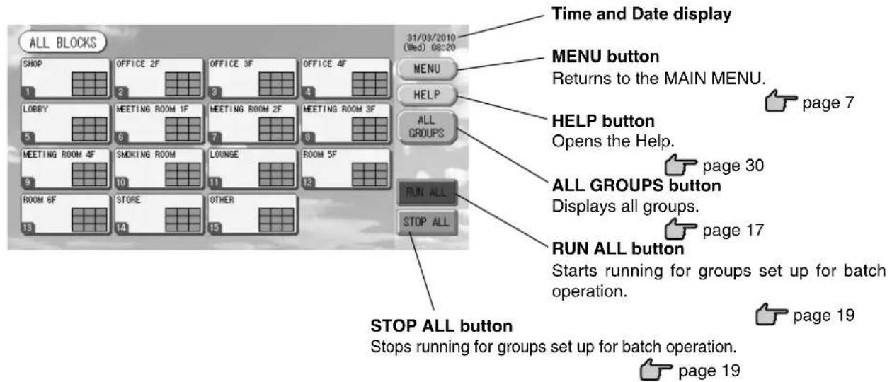
All Blocks Display
This is displayed when the ALL BLOCKS button is pressed on the MAIN MENU. Page 7 The names and the status of all blocks are displayed in the panels. Unestablished blocks or blocks without any groups are not displayed. If a block button is pressed, the GROUP (PANEL) screen is displayed.
page 15
- Settings can also be made for groups not set up for batch operation.

page 11 ①
page 12 ⑤⑥
- Individual Block Displays
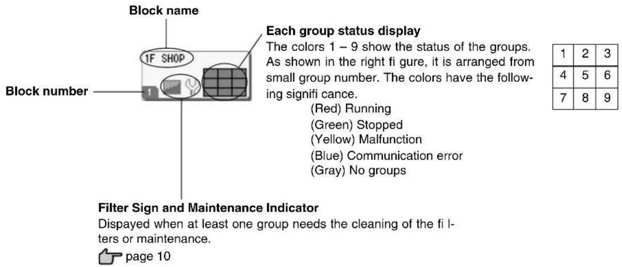
Icons
(1) Unit icon
The unit status is shown by colors.
(Red) Running (when at least one unit is running)
(Green) Stopped (when all units are stopped)
(Yellow) Malfunction of one or more units
(Blue) Communication error with one or more units
(2) Filter sign
If at least one air conditioning unit in a block or group needs fi iter maintenance, this indicator lights up. When this happens, clean the fi iters.

(3) Maintenance Indicator
When the maintenance indicator is lit for at least one air conditioning unit in a block or group, the maintenance indicator is displayed. If the maintenance indicators are off on all units, the maintenance indicator turns off. Contact the shop where the units were purchased if this indicator is on.

(Gray) Inspection, Inspection 1, Inspection 2

(Yellow) Backup operation (Inspection 3)
(4) Scheduling
This shows the groups that are the targets of the current day's schedule.

(5) Air direction
This shows the status of louver operation.

Swinging (AUTO)

Position 1 (STOP 1)

Position 2 (STOP 2)

Position 3 (STOP 3)

Position 4 (STOP 4)
(6) Unit states
The unit status is shown by figures.

Error stop (One or more units have been stopped because of malfunction.)
Please contact the shop where the unit was purchased.

Demand (The external signal is input to the demand terminal. page 12)
The target unit will switch to fan mode and remote controller operations are prohibited. When the external signal is cancelled, the setting will return.

Emergency stop (The external signal is input to the emergency stop terminal.)
All connected units stop and are prohibited operation. When the emergency stop signal is cancelled, the remote controller lock/unlock setting will be reverted but the units remain stopped. If schedule setting was done, the units start operation according to the set schedule.
Changeover Confirma rmination Screen

This is a screen for confirming the changes to various settings. The text displayed varies according to the screen called up, but the operation is as follows.
Press the Yes button to save the settings and to exit. Press the No button to exit without saving your settings.
Operation
Attention
A static electric discharge to the unit could cause a break-down.
Before performing operations, touch a grounded metal object and discharge any static electricity.
Time & Date Setting
- Press the MENU button and then press the SYSTEM CONFIG. button.
- Press the TIME&DATE SETTING button on the SYSTEM CONFIGURATION screen. page 8
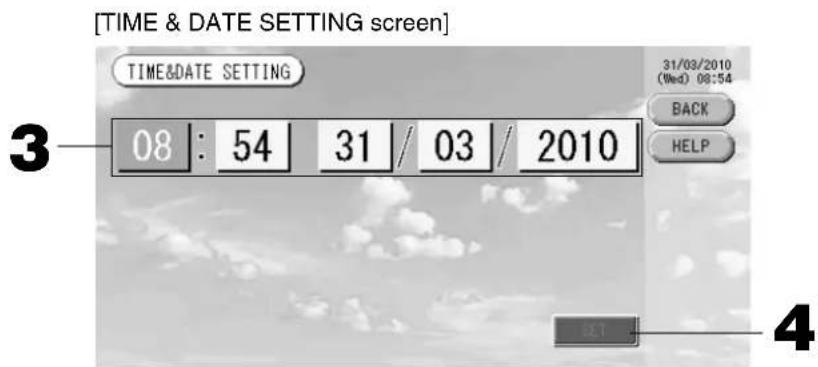
- Press the Year, Month, Day and Time buttons.
Input the current time and date. page 26
- Press the SET button, and press the Yes button on the confirmation screen.
The specified date and time are set at the 00 seconds. When you do not want to make the setting, press the No button.
Note
- If the BACK button is pressed, it will return you to the SYSTEM CONFIGURATION screen.
- It is unnecessary to reset the time and date for power outages lasting less than 48 hours.
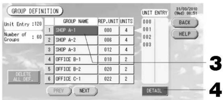
Group Definition
① Selecting the groups to register and display the registered units
- Press the SYSTEM CONFIG. button on the MAIN MENU.

page 7
- Press the GROUP DEFINITION button on the SYSTEM
CONFIGURATION screen page 8
The GROUP DEFINITION screen is displayed.
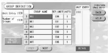
[Initial GROUP DEFINITION screen]
Initial GROUP DEFINITION screen may vary according to the transmission method.
(Example for previous setting)
1
SuperLink No. Unit address
(Example for new setting) 005
Unit address
One indoor unit is registered with one group on the initial screen previously.
When registering the indoor unit to other groups, register it with other group after deleting it from the group, and moving it in the list of ALL UNITS.
- Select a group name.
When adding a group, press an empty group name area. When changing the settings for a registered group, press that group name. The selected group is reverse highlighted. To change the page, press the PREV or NEXT button.
4. Press the DETAIL button.
The GROUP DEFINITION DETAILS screen is displayed.
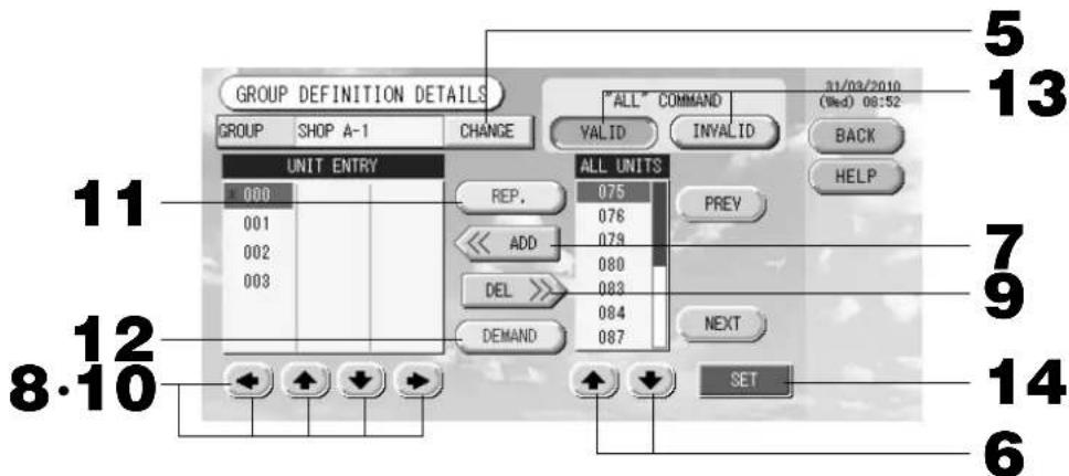
② Registering and changing the Group Name being set
5. Press the CHANGE button.
Enter the name for the group. page 26
③ Adding and deleting units making up the group
- or directly press a unit name to select the unit from the list of ALL UNITS.
To change the page, press the PREV button or the NEXT button.
7. Press the ADD button.
The selected unit is added to the list of UNIT ENTRY and deleted from the list of ALL UNITS.
- or directly press a unit name to select the unit from the list of UNIT ENTRY.
9. Press the DEL button.
The selected unit is deleted from the list of UNIT ENTRY and moved to the list of ALL UNITS.
(4) Setting the representative unit and demand
- or directly press a unit name to select the unit from the list of UNIT ENTRY.
11. Press the REP. button
That unit is set as the representative unit, and an asterisk is placed to the left of its name in the display.
Representative unit: unit for which the status is shown when the group is displayed
12. Press the DEMAND button.
That unit is set as the for demand operation, and a "D" is placed to the right of its name in the display.
- Demand: a unit that switches to fan mode and then cannot be operated from the remote controller when there is an external demand input.
Note
By the demand input, it is possible to save on power costs in summer by reducing the power consumption. Operation of the unit when demand input is released, is conformed to nearest schedule before release time of the day.
In case of that schedule of the day is not set, the unit is for the operation mode and remote controller permission prohibited setting which is just before the demand input.
⑤ Setting and unsettling batch operation for the group
13. Press the VALID or INVALID button.
- VALID: group set up for batch operation
- INVALID: group not set up for batch operation
⑥ Saving the settings
14. Press the SET button. Press the Yes button on the confirmation screen.
The group settings are saved. When you do not want to save the settings, press the No button.
Note
- If the BACK button is pressed, it returns to the previous screen.
- 1 to 16 units can be registered in a group.
- When you will delete all group defi nition, please press the DELETE ALL DEF. button and enter your password () . Press the Yes button on the confirmation screen.
Caution
The all schedule settings are deleted too.
(*) Refer to page 6.
Block Defi nition
Note
Register the group beforehand. page 11
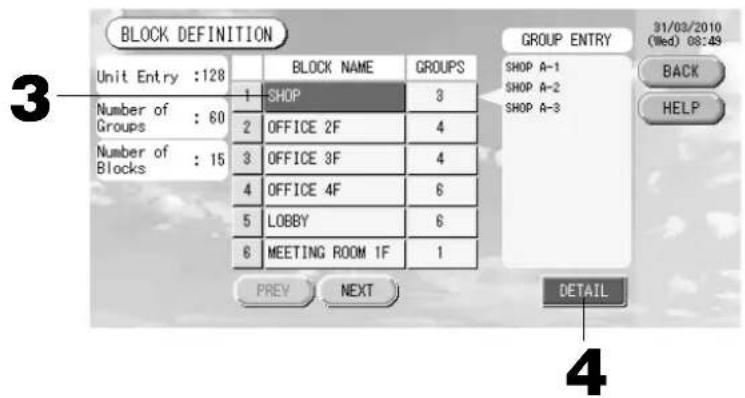
① Selecting the blocks to define and displaying the registered groups
- Press the SYSTEM CONFIG. button on the MAIN MENU. page 7
- Press the BLOCK DEFINITION button on the SYSTEM CONFIGURATION screen. 1 page 8 The BLOCK DEFINITION screen is displayed.
[Initial BLOCK DEFINITION screen]
When defining a new block, the block names and registered groups are empty.
3. Select a block name.
When adding a block, select an empty block name area. When changing the settings for a registered block, press that block name. The selected block is reverse highlighted. To change the page, press the PREV or NEXT button.
4. Press the DETAIL button.
The BLOCK DEFINITION DETAILS screen is displayed.
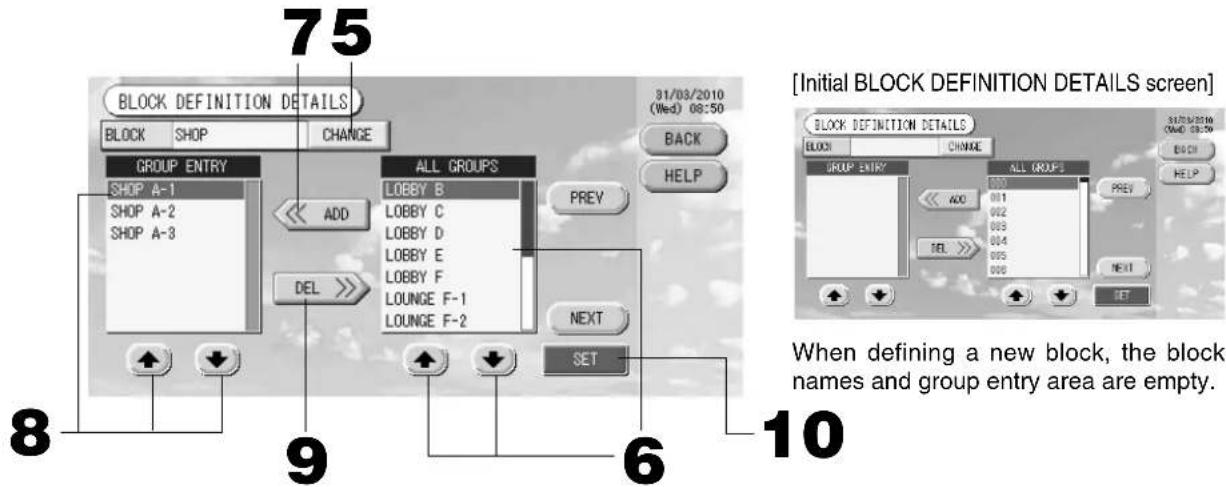
② Registering and changing the Block Name being set
5. Press the CHANGE button.
Enter the name for the block. 5 page 26
③ Adding and deleting groups registered in a block
When adding groups>
- () or directly press the group name to select the group from the list of ALL GROUPS.
When changing the page, press the PREV or NEXT buttons.
- Press the ADD button.
The selected group is added to the group entry list and deleted from the list of ALL GROUPS.
- + or directly press the group name to select the group from the list of GROUP ENTRY.
- Press the DEL button.
The selected group is deleted from the list of GROUP ENTRY and moved to the list of ALL GROUPS.
④ Saving the registrations and changes
- Press the SET button. Press the Yes button on the confirmation screen.
The block settings are saved. When you do not want to save the settings, press the No button.
Note
- If the BACK button is pressed, it returns to the previous screen.
- 1 to 9 groups can be registered in a block. In addition, the maximum number of blocks is 16.
- If any unconnected indoor units are registered with groups, "Communication Error" is displayed, and it may affect to the communication of the entire system, and may result unintended operation. Be sure not to register unconnected indoor units with groups.
- In the initial setting of GROUP DEFINITION, each indoor unit is registered with each predefined group. However if unconnected indoor units are included, they must be removed from the groups one by one. Therefore, when defi ning groups newly, deleting all predefi ned groups once with the "DELETE ALL DEF." button and re-registering only the connected indoor units with the groups is comparatively easier than changing predefi ned groups individually, and can prevent "Communication Error" from occurring.
Group Operation Settings (Monitor Group Status)
- Press the ALL BLOCKS button on the MAIN MENU. Page 7
- Press the block you wish to set or monitor.
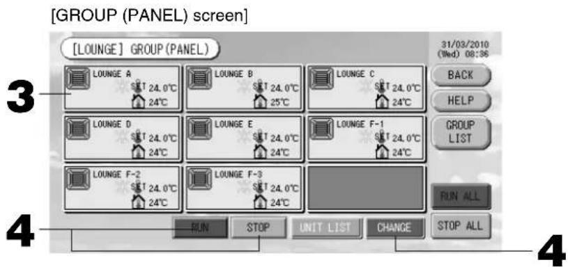
The GROUP (PANEL) screen is displayed.
The group name, status, fi ler sign, maintenance, scheduling, temperature settings and room temperature can be observed.
Note
SeeIcons for the signifi cance of the icon displays. Page 10
- The running status, operating mode, temperature settings and room temperature are shown for the representative unit. When all units are stopped, stopped status is shown.
- Groups that have the current day's schedule settings show ①
being displayed means that these are lit for one or more units.
- If the GROUP LIST button is pressed, the GROUP (LIST) is displayed.
To display the units in a group, press the UNIT LIST button. Page 24
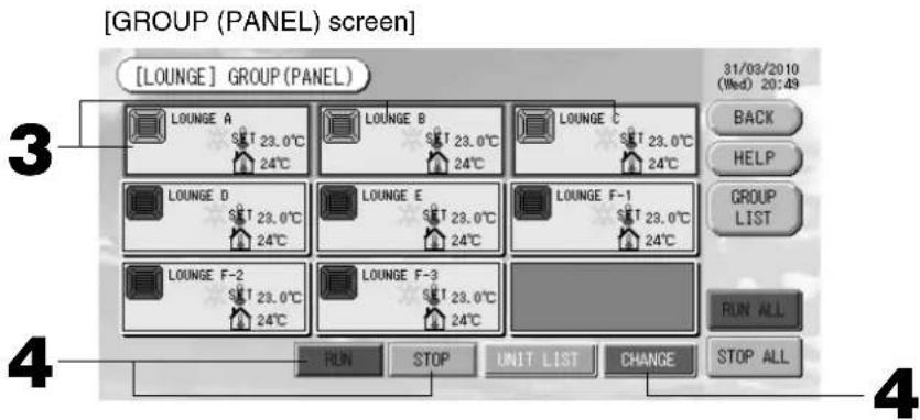
- Press the panel of the group for which settings are to be made.
The panel frame turns blue.
- To run units Press the RUN button, and press the Yes button on the confirmation screen.
The selected group starts running.
To stop units Press the STOP button, and press the Yes button on the confirmation screen.
The selected group stops running.
When you do not want to set, press the No button.
- Press the panel of the group for which settings or changes are to be made.
The panel frame turns blue.
- Press the CHANGE button.
The screen for basic group settings is displayed. When the screen changes, no items are selected (the temperature setting is blank). Set only the items that are to be set or changed.
[BASIC GROUP SETTINGS screen]
![MITSUBISHI SCSL3NAAE - [BASIC GROUP SETTINGS screen] - 1](/content/2026/03/428779/images/1f8f10da73fc169cdc4e0d544b3418066e2c387a6cfc4e5e414defcf9e720b80.jpg)
[Auto button enabled in Function Setting]
![MITSUBISHI SCSL3NAAE - [Auto button enabled in Function Setting] - 1](/content/2026/03/428779/images/0e7fb61f36e606484cc172517127ca5456da633c8ef4d7f92c3ab29857e49eae.jpg)
This function can be applied to the outdoor units, which are the cooling / heating free multi KXR, GHP-R series or later and PAC.
5. Press the button for the item to set or change.
- Run/Stop: Press the RUN or STOP button.
With the RUN button is selected, the operation starts, and with the STOP button is selected, the operation stops.
- Temperature setting: press▲ or▼.
Set a temperature between 18^ and 30^ .
Mode: select Auto, Cool, Dry, Fan or Heat by pressing the button.
-
Auto Mode can be enabled in the Function Settings. Page 27
-
Fan speed: select all, and press the button.
can be enabled in the Function Settings.
- Air direction: select Auto, stop 1, stop 2, stop 3 or stop 4 and press the button.
The unit operates with the maximum fan speed.
6. Press the SET button. Press the Yes button on the confirmation screen.
When you do not want to make the setting or change, press the No button.
Settings/changes on the detailed group settings screen.
Prohibiting operations by remote controller settings and fi iter resets can be carried out on this screen.
Press the DETAIL SET button on the BASIC GROUP SETTINGS screen. Above
The DETAILS GROUP SETTINGS screen is displayed.
[DETAILS GROUP SETTINGS screen]
![MITSUBISHI SCSL3NAAE - [DETAILS GROUP SETTINGS screen] - 1](/content/2026/03/428779/images/e7039ad24936e146b20141cc114c0efe76dc29efaa61828ec03334b8dfe7f995.jpg)
[Individual lock / unlock settings enabled in Function Setting]
![MITSUBISHI SCSL3NAAE - [Individual lock / unlock settings enabled in Function Setting] - 1](/content/2026/03/428779/images/e886ae1a6d849378153d037c78a2cb8b857377a9734ab6600cdc9bc755423382.jpg)
This function can be applied to the indoor units, which are the model KXE4 or later, and to the remote controller, which is the model RC-E1 or later.
5. Press the button for the item to set or change.
-
Run/stop, temperature setting and mode are the same as the BASIC GROUP SETTINGS screen.
-
LOCK: Press or
If is pressed, remote controller operations are permitted, and if is pressed, they are prohibited.
- FILTER: if the reset button is pressed, the fi lter sign turns off.
6. Press the SET button. Press the Yes button on the confirmation screen.
When you do not want to set or change, press the No button.
Note
- If the BACK button is pressed, it returns to the previous screen.
- If individual lock/unlock is enabled in the Function Setting, it is possible to set the remote controller operations to permit or prohibit each item such as run/stop, mode and temperature setting.
- When individual lock/unlock are enabled in the Function Setting, remote controller operations are prohibited if run/stop, mode and temperature setting are all. (Some functions, such as reset of the fi Iter sign have been permitted.)
The following method can also be used to set and change operations on each group.
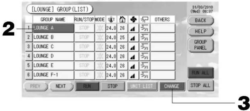
When making settings or changes in the GROUP (LIST) screen
- Press the GROUP LIST button in the GROUP (PANEL) screen. Page 15 The GROUP (LIST) screen is displayed.
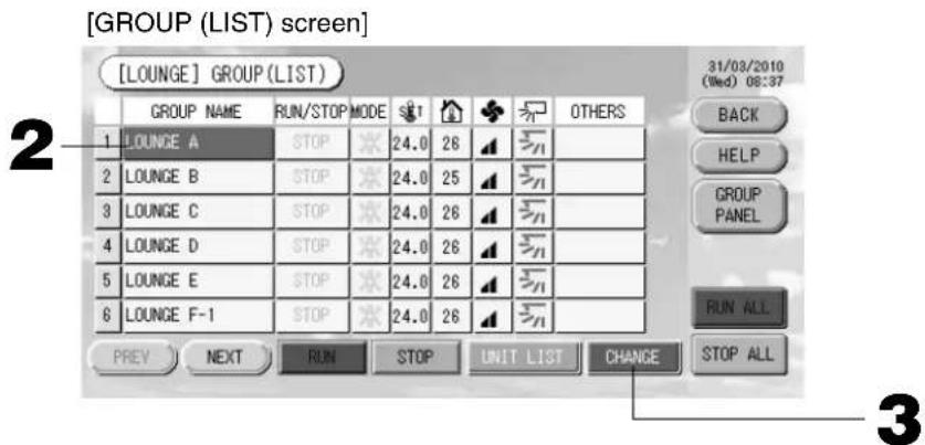
- Press the name of the group for which settings or changes are to be made.
The group name is reverse highlighted. To change the page, press the PREV or NEXT button.
- Press the CHANGE button.
The screen for basic group settings is displayed. Make the settings or changes.
Note
- If the BACK button is pressed, it returns to the previous screen.
- Run is indicated when at least one unit is running. Malfunctions are indicated when at least one unit is not in good condition. Stop is indicated when all the units have stopped.
icon is displayed when at least one unit needs to clean.
icon is displayed when at least one unit needs the maintenance.
Operating mode, temperature setting, room temperature, fan speed and air direction show the state of the representative unit.
- Ones which are surrounded by orange frames are the items which operations from the remote controller are prohibited in the group settings.
- If the GROUP PANEL button is pressed, the GROUP (PANEL) screen is displayed. Page 15
When making settings or changes in the ALL GROUPS screen
- Press the ALL GROUPS button on the MAIN MENU. Page 7
- Press the name for the group to set or change.
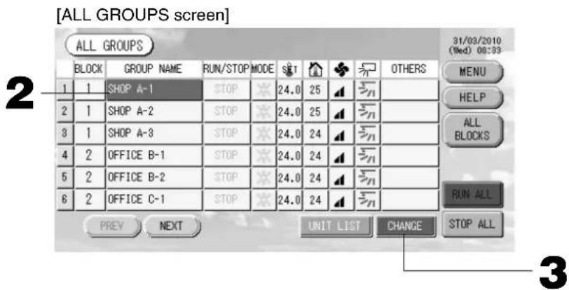
The group name is reverse highlighted.
When the screen switches, the previously selected group name is selected. To change the page, press the PREV or NEXT button.
3. Press the CHANGE button.
The screen for basic group settings is displayed. Make the settings or changes. Page 16
Note
To display the units in a group, press the UNIT LIST button. Page 24
- To show all blocks, press the ALL BLOCKS button.
- Ones which are surrounded by orange frames are the items which operations from the remote controller are prohibited in the group settings.
- If the MENU button is pressed, the MAIN MENU is displayed.
Multiple Groups Operation Settings
This section shows how to operate multiple groups in a same block.
- Press the ALL BLOCKS button on the MAIN MENU. Page 7
- Press the block you wish to set.
The GROUP (PANEL) screen is displayed.
- Press the panels of the groups for which settings are to be made (multiple groups can be selected). The panel frame turns blue.
When you want to cancel, please press the panel of the group again.
- To run units Press the RUN button, and press the Yes button on the confirmation screen.
The selected group starts running.
To stop units Press the STOP button, and press the Yes button on the confirmation screen.
The selected group stops running.
When you do not want to set, press the No button.
- Press the panels of the groups for which settings or changes are to be made (multiple groups can be selected).
The panel frame turns blue.
When you want to cancel, please press the panel of the group again.
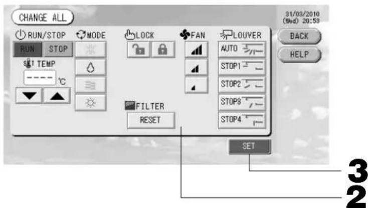
- Press the CHANGE button.
The screen to change groups is displayed. When the screen changes, no items are selected (the temperature setting is blank). Set only the items that are to be set or changed.
[Individual lock/unlock settings enabled in Function Setting]
This function can be applied to the indoor units, which are the model KXE4 or later, and to the remote controller, which is the model RC-E1 or later.
5. Press the button for the item to set or change.
- Run/Stop: Press the RUN or STOP button.
With the RUN button, running starts, and with the STOP button, running stops.
- Temperature setting: Press▲ or▼.
Set a temperature between 18 and 30^
Mode: Select Auto, Cool, Dry, Fan or Heat by pressing the button.
-
Auto mode can be enabled in the Function Settings. Page 27
-
LOCK: Press or
If is pressed, remote controller operations are permitted, and if is pressed, they are prohibited.
Fan speed: select and press the button.
can be enabled in the Function Settings.
Air direction: select Auto, stop 1, stop 2, stop 3 or stop 4 and press the button.
- FILTER: if the reset button is pressed, the fi Iter sign turns off.
The unit operates with the maximum fan speed.
6. Press the SET button. Press the Yes button on the confirmation screen.
When you do not want to set, press the No button.
Note
- If the BACK button is pressed, it returns to the previous screen.
- If individual lock/unlock is enabled in the Function Setting, it is possible to set the remote controller operations to permit or prohibit each item such as run/stop, mode and temperature setting.
- When individual lock/unlock are enabled in the Function Setting, remote controller operations are prohibited if run/stop, mode and temperature setting are all. (Some functions, such as reset of the fi Iter sign have been permitted.)
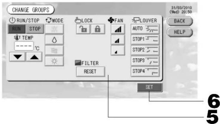
Group Batch Operation
This section shows how to set or change the detailed setting of Batch Operation.
Set the groups for batch operation in advance. Page 11①, 12⑤⑥
1. Press the CHANGE ALL button on the MAIN MENU. Page 7
The CHANGE ALL screen is displayed.
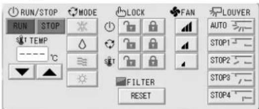
[Individual lock/unlock settings enabled in Function Setting]

This function can be applied to the indoor units, which are the model KXE4 or later, and to the remote controller, which is the model RC-E1 or later.
Note
When the screen changes, no items are selected (the temperature setting is blank). Set only the items that are to be set or changed.
2. Press the button for item to set or change.
- Run/Stop: Press the RUN or STOP button.
With the RUN button, running starts, and with the STOP button, running stops.
- Temperature setting: Press▲ or▼.
Set a temperature between 18 and 30^
Mode: Select Auto, Cool, Dry, Fan or Heat by pressing the button.
-
Auto mode can be enabled in the Function Settings. Page 27
-
LOCK: Press or
If is pressed, remote controller operations are permitted, and if is pressed, they are prohibited.
Fan speed: select and press the button.
can be enabled in the Function Settings.
Air direction: select Auto, stop 1, stop 2, stop 3 or stop 4 and press the button.
- FILTER: if the reset button is pressed, the filter sign turns off.
The unit operates with the maximum fan speed.
3. Press the SET button. Press the Yes button on the confirmation screen.
When you do not want to set, press the No button.
Note
- If the BACK button is pressed, it returns to the previous screen.
- If individual lock/unlock is enabled in the Function Setting, it is possible to set the remote controller operations to permit or prohibit each item such as run/stop, mode and temperature setting.
- When individual lock/unlock are enabled in the Function Setting, remote controller operations are prohibited if run/stop, mode and temperature setting are all. (Some functions, such as reset of the filter sign have been permitted.)
Schedule Settings
Operating schedules can be set in group units. Sixteen schedules per day can be registered for operating time (in minutes), run/stop, mode, prohibiting remote controller operations and temperature setting.
Set the detailed daily schedule (weekday, holiday, special 1, special 2) in advance. Page 21
1. Press the SCHEDULE SETTING button on the MAIN MENU. Page 7
The SCHEDULE SETTING screen is displayed.
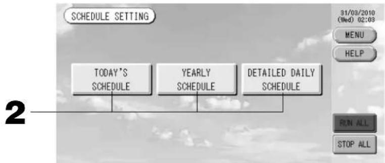
Setting the current day's schedule
The operating schedule for the current day is set on each group.
- Press the TODAY'S SCHEDULE button on the SCHEDULE SETTING screen.
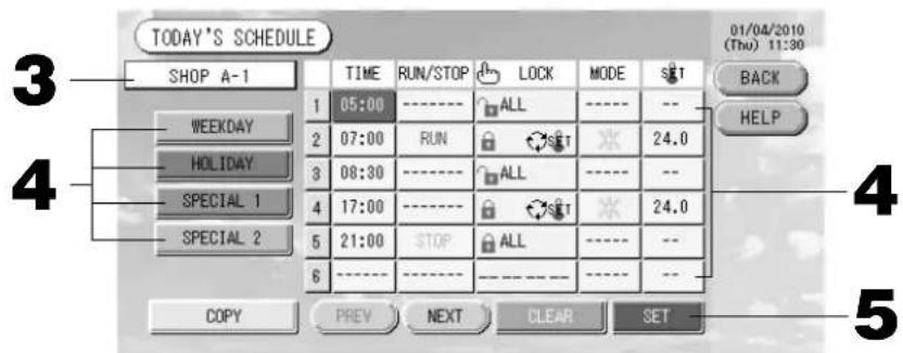
3. Press the group name.
Select the group on the Select Group screen.

Page 22
4. Press the item to be changed on the list.
When "Time", "Lock" or "Temperature setting" buttons are pressed, a detailed setting screen for each item is indicated. Page 22, 23
Change the "RUN/STOP" or "MODE" settings by pressing the appropriate item.
To change the page, press the PREV or NEXT button.
4. Select the detailed daily schedule such as WEEKDAY, HOLIDAY, SPECIAL 1 or SPECIAL 2 button and press it.
Note
Set the operating schedule for the detailed daily schedule in advance.
Noted below (Setting a detailed daily schedule)
5. Press the SET button. Press the Yes button on the confirmation screen.
When the CLEAR button is pressed, the selections are cleared.
Note
- If the BACK button is pressed, it returns to the SCHEDULE SETTING screen.
- Press the COPY button when copying the schedule between groups. Page 23
Setting a yearly schedule
A yearly operation schedule is set on each group. (The yearly schedule is not reflected in the following year and has to be set once every year.)
2. Press the YEARLY SCHEDULE button on the SCHEDULE SETTING screen.
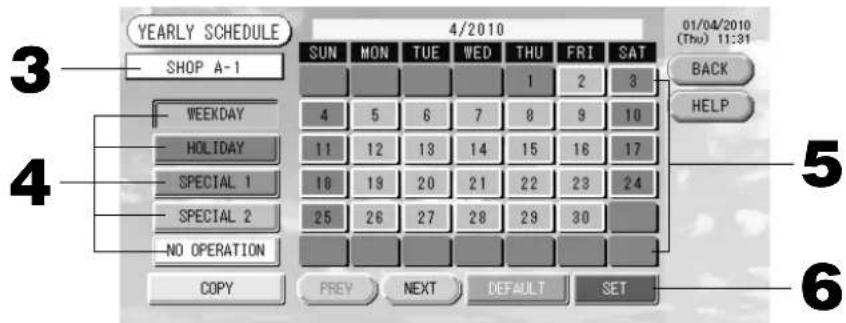
3. Press the group name.
Select the group on the Select Group screen.

Page 22
4. Select the detailed daily schedule such as ERATION button and press it.
WEEKDAY, HOLIDAY, SPECIAL 1, SPECIAL 2 or NO OP
Note
Set the detailed daily schedule in advance.

Noted below (Setting a detailed daily schedule)
5. Press the date (multiple dates can be selected).
The detailed daily schedule which you choose is applied to that day. However, the current day and the dates which have elapsed can not be selected. Press the PREV or NEXT button to change the month.
Note
If the DEFAULT button is pressed, Saturday and Sunday are set as holidays and the others are set as weekdays.
6. Press the SET button. Press the Yes button on the confirmation screen.
When you do not want to set, press the No button.
- If the BACK button is pressed, it returns to the SCHEDULE SETTINGS screen.
- Pressing the COPY button brings up the Copy Schedule screen when copying between groups.

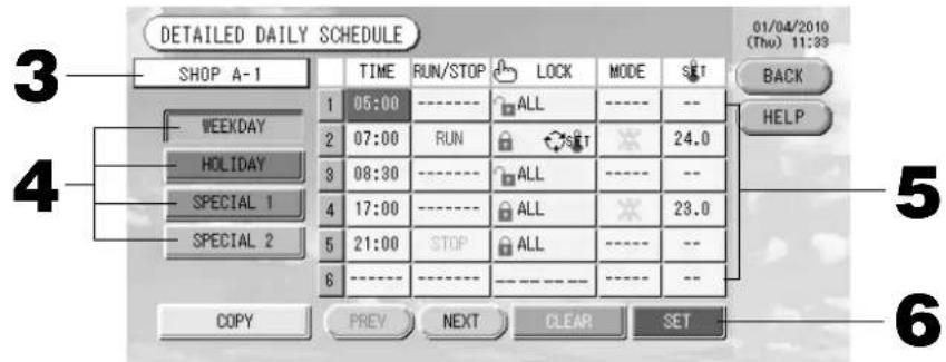
Setting a detailed daily schedule
The detailed daily schedule is set for each group.
The schedule indicates weekday, holiday, special 1 and special 2, and the operation can be set for each group.
-
Press the DETAILED DAILY SCHEDULE button on the SCHEDULE SETTING screen.
-
Press the group name.
Select the group on the Group Select screen. Noted below (Various screens)
-
Select the detailed daily schedule such as WEEKDAY, HOLIDAY, SPECIAL 1 or SPECIAL 2 button and press it.
-
Press the item to be changed on the list.
When "Time", "Lock" or "Temperature setting" buttons are pressed, a detailed setting screen for each item is indicated. Page 22, 23
Change the "Run/Stop" or "MODE" setting by pressing the appropriate item.
To change the page, press the PREV or NEXT button.
- Press the SET button. Press the Yes button on the confirmation screen.
When the CLEAR button is pressed, the selections are cleared.
Note
- If the BACK button is pressed, it returns to the SCHEDULE SETTING screen.
- Press the COPY button when copying the schedule between groups. Page 23
Various screens
[Select Group screen]
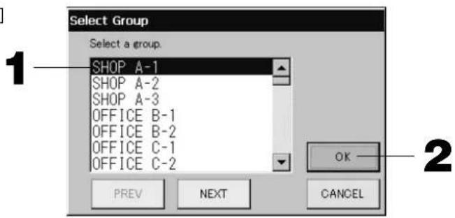
- Press the group name to be selected.
The selected group name is reverse highlighted.
To change the page, press the PREV or NEXT button.
- Press the OK button.
The selected group can be set.
When you do not want to set, press the CANCEL button. It returns to the previous screen.
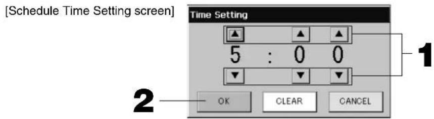
- Pressing changes the hour and minutes (24 hour clock display).
- Press the OK button.
The time is changed and the screen closes. Press the CANCEL button to cancel the change.
Pressing the CLEAR button clears the currently entered values and makes the entry empty.
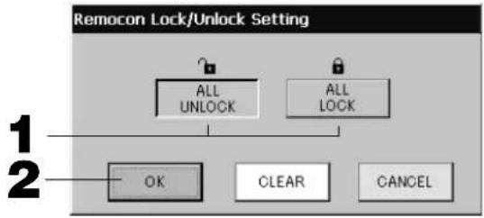
[Remote Controller Lock/Unlock screen] This is used to allow or prohibit remote controller operations.
[Individual lock/unlock settings enabled in Function Setting]
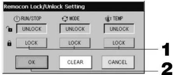
- Press the button of the items which are to be barred from the remote controller operation (multiple items can be selected).
- Press the OK button.
The prohibited item changes and the screen closes.
Press the CANCEL button to cancel the change.
If the CLEAR button is pressed, the selected item is deselected.
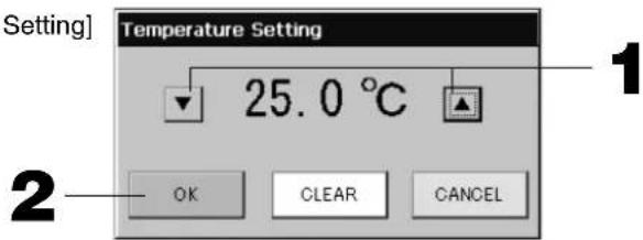
[Schedule Temperature Setting screen]
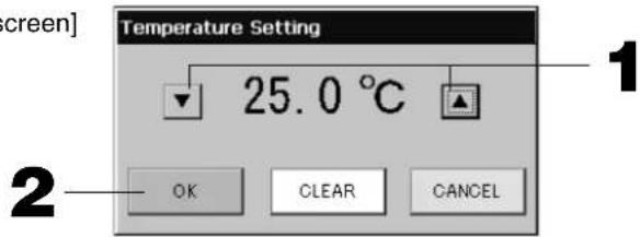
- Pressing ▲▼ changes the temperature. (18 - 30°C)
- Press the OK button.
The temperature changes and the screen closes.
Press the CANCEL button to cancel the change.
Pressing the CLEAR button clears the currently entered values and makes the entry empty.
[Copy Schedule screen]
Select the groups that apply the chosen schedule.
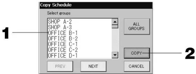
- Press the group name to be selected (multiple groups can be selected).
To change the page, press the PREV button, the NEXT button or
To select all groups, please press the ALL GROUPS button. If you will cancel the selecting all groups, press the ALL GROUPS button again.
- Press the COPY button. Press the Yes button on the confirmation screen.
The schedule of the group chosen on the screen is pasted to the groups checked in the list. When you do not want to make the setting, press the No button.
Note
- This is cancelled if the selected group is pressed two times.
- If the CANCEL button is pressed, it returns to the previous screen.
Viewing Detailed Unit Information
The unit numbers and status of each group can be observed.
- Press the UNIT LIST button in the ALL GROUPS screen (Page 17) or if the UNIT LIST button is pressed in the GROUP (PANEL) or GROUP (LIST) screen (Page 15, 17).
The units in the group are displayed.
To change the page, press the PREV or NEXT button.
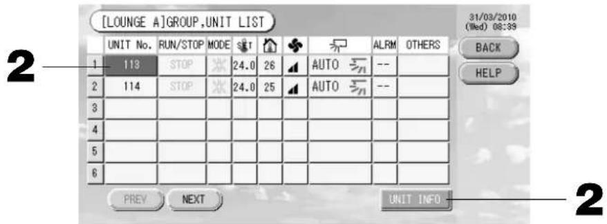
- To view further information, press the unit number. After it is reverse highlighted, press the UNIT INFO button.
The information for the specified unit is displayed.
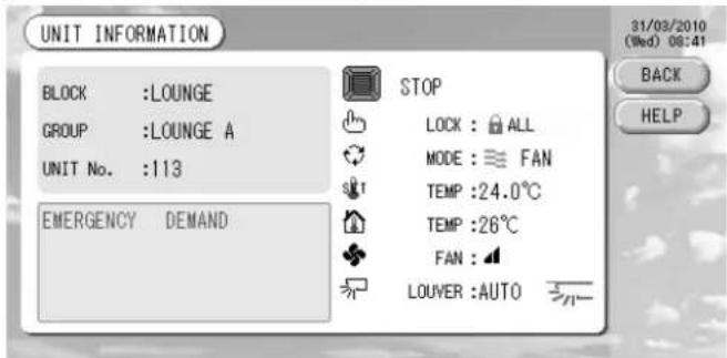
[UNIT INFORMATION screen]
Note
- The detail of the maintenance display content can be checked only on this screen. On other screens, there is only a color classifi cation of Inspection 1, 2 and backup operation.
- If the BACK button is pressed, it returns to the previous screen.
- UNIT No. display system may differ from the fi guration. (Same as every other screen)
Display system is changed according to the communication method (Page 27 Function Setting, SL Mode).
Prev. SL) [3-04] New SL) [005]
SuperLink No. unit address unit address
Calculating Settings (SC-SL3NA-BE only)
① Unit Defi nition
- Press the UNIT DEFINITION button on the SYSTEM CONFIGURATION screen. Page 8 The UNIT DEFINITION screen is displayed.
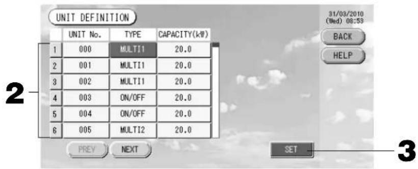
2. Press the item to be set or changed on the list.
Each time the "TYPE" item is pressed, the unit type changes.
MULTI1 : calculating according to the amount of refrigerant flow. Used for KX Series and GHP.
MULTI2 : thermo ON/OFF calculating. Used for KX Series and GHP.
RUN/STOP : calculating according to the unit operating time. Used for KX series, PAC and GHP.
If the "CAPACITY" item is pressed, it can be changed. (0 - 200 [kW])
To change the page, press the PREV or NEXT button.
Note
- Please select same item for same system of wattmeter or gas meter.
- When you select MULTI1 or MULTI2, fan mode units are out of calculation. To calculate the fan mode units, please select RUN/STOP.
- Standby energy used during night etc. is not included in the calculation, and does not equal the value of wattmeter or gas meter. Please correct the calculation by spreadsheet.
3. Press the SET button. Press the Yes button on the confirmation screen.
When you do not want to make the setting, press the No button.
If the BACK button is pressed, it returns to the SYSTEM CONFIGURATION screen.
② Setting the period for calculation
You can divide a day into two periods for calculation.
If it is not necessary to devide the period into two parts, you can set the period time for 0:00 - 24:00.
- Press the ACCOUNTING PERIOD button on the SYSTEM CONFIGURATION screen. Page 8
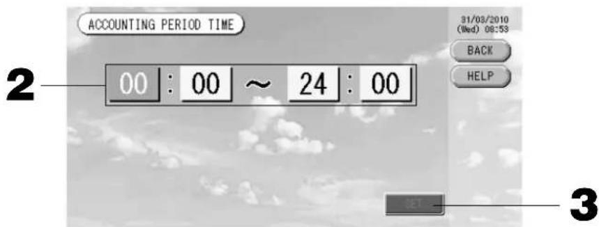
2. Press the hour or minute buttons for the start time or the end time.
Input the time. Page 26
3. Press the SET button. Press the Yes button on the confirmation screen.
When you do not want to set, press the No button.
If the BACK button is pressed, it returns to the SYSTEM CONFIGURATION screen.
Caution
The energy consumption calculated by this unit does not conform to OIML, and there are no guarantees concerning the results of the calculations.
This unit calculates only energy consumption distribution (gas, electric power). You need to calculate the air-conditioning rates.
The calculating data for twelve months are saved.
See page 28 (Using USB Memory) for the method for extracting calculating data.
Convenient Functions
Entering Numbers and Characters
■ Entering numbers
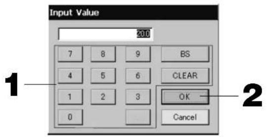
- Press the button of the numerical value to input.
BS button : backspaces. (Deletes one number.)
CLEAR button : clears the input. (Deletes all numbers.)
- Press the OK button.
The number is changed and the screen closes. Press the Cancel button to cancel the change.
■ Entering characters

- Select a letter and press the button.
- Input the group name.
When ABC or abc button is selected, several letters are assigned to each button, and each time the button is pressed the character changes.
ABC button : capital letters are input.
abc button : small letters are input.
123 button : numbers are input.
BS button : backspaces. (Deletes one character.)
SPC button : inputs a space.
< > buttons : moves the cursor to the left or right.
- Press the OK button.
The name is changed and the screen closes. Press the Cancel button to cancel the change.
- The block or the group names can be input up to 16 characters.
Function Settings
The timeout for turning OFF the backlight, validating or invalidating of the auto mode button and locking or unlocking the individual functions of the remote controller are set.
When changing the Function Settings, follow the following steps.
- Press the FUNCTION SETTING button on the MAIN MENU.

Page 7

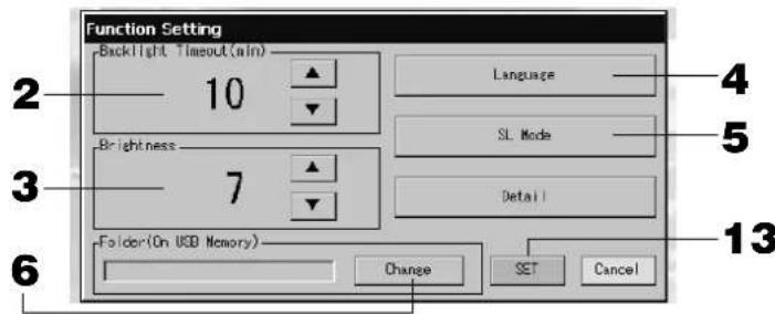
[Function Setting screen]
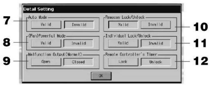
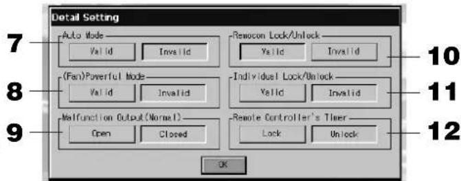
[Detail Setting screen]
- Select the Backlight Timeout time using the buttons. (Factory default: 10)
Time from the last operation on the touch panel until the monitor backlight turns OFF can be selected.
- Select the Brightness using the buttons. (Factory default: 7)
Brightness for the monitor backlight can be selected.
- Change "Language". Pressing this button allows you to select the desired language.
Please contact the shop where the unit was purchased.
- Change "SL-Mode". Use it when set the communication system (Factory default: New). Usually, this is not necessary to change it.
If setting is incorrect, this may cause no communication with a part or all of air conditioners.
Please contact the shop where the unit was purchased.
- Press the Change button.
You can specify the folder to transfer the calculated data to USB memory. (SC-SL3NA-BE only)
- Press the "Valid" or "Invalid" button for the Auto Mode. (Factory default: Invalid)
This enables or disables the AUTO button on the GROUP SETTINGS screen and CHANGE All screen. If you set Auto Mode to INVALID, Auto button is not shown on the screen.
This function can be applied to the outdoor units, which are the cooling / heating free multi KXR, GHP-R series or later and PAC.
For other than the outdoor units above, please do not use Auto Mode.
Please contact the shop where the unit was purchased.
- Press the "Valid" or "Invalid" button for the Fan Powerful Mode. (Factory default: Invalid)
This enables or disables button on the GROUP SETTINGS screen and CHAGE All screen.
If you set Fan Powerful mode to Invalid, button is shown on the screen.
Please contact the shop where the unit was purchased.
- Select the "Closed" or "Open" for the Malfunction Output (Normal). (Factory default: Closed)
You can choose "Closed" or "Open" status for malfunction output during normal operation of air conditioning unit.
Contact your service representative or installer for further information.
- In case of managing one air conditioner with plural center consoles, regarding the prohibition setting of remote controller if the different settings from plural center consoles are done on this air conditioner, it may cause that this air conditioner cannot start operation by the remote controller despite the intention of user. Accordingly, in this case, be sure to make permission/prohibition setting only with the master center console, not with slave center consoles.
(Factory default :Valid)
In addition, make this setting to "valid" when the external input wiring such as emergency stop input are connected to this central control.
Please contact the shop where the unit was purchased.
11. Press the "Valid" or "Invalid" button for the Individual Lock/Unlock. (Factory default: Invalid)
This enables or disables permitting and prohibiting the individual operation such as run/stop, mode and temperature settings of the remote controller.
Note
This function can be applied to the indoor units, which are the model KXE4 or later, and to the remote controller, which is the model RC-E1 or later.
12. Press the "Unlock" or "Lock" button for the Remote Controller's Timer. (Factory default: Unlock)
This permits or prohibits remote controller's timer operation for all the air conditioners defined in a group.
13. Press the SET button.
Press the Cancel button to cancel the change.
Note
Set the timeout of the backlight as short as possible in order to make the lifetime of LCD longer.
Corrections for Power Outages
Data maintained during a power outage
- System configuration defined on Page 8
Schedule settings made on Page 20 - Function setting made on Page 27
- Calculation data of power consumption until the power outage (SC-SL3NA-BE only)
Data not maintained during a power outage
- Operating conditions and preset status of each indoor unit before the power outage (including the operation mode, set temperature, and preset status for permitting or prohibiting remote controller operation and etc.).
In case the blackout continues more than 48 hours, the clock inside will stop and the operation of each group cannot follow any schedule settings. Please reset the clock.
In case the blackout continues less than 48 hours, you do not have to reset the clock, and each group will run/ stop according to the following rule.
When the power returns, the operation of each group will follow the closest schedule setting before the power returns. In case there are no settings in the closest schedule setting, it will follow the second closest schedule setting.
In case there are no schedule settings on that day, this center console will not send any operation signal to each group.
Using USB Memory
Attention
- Be sure to use bundled USB memory.
- Be sure to perform these operations after inserting the USB memory into the unit.
- The calculating data for twelve months are saved. Please save it to a PC through the USB memory within twelve months.
- Please do not operate while the display light of the USB memory is blinking fast.
You may perform your operations or remove the USB memory only when the display light is blinking slowly.
If the USB memory you use does not have a red blinking light, please wait for a moment after each operation.
Remove the USB memory only after all operations have been completed.
It is convenient if folders are created in the USB memory in advance.
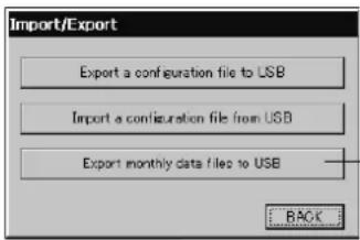
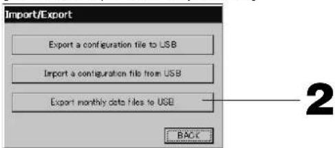
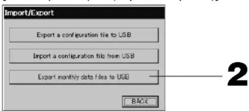
- Press IMPORT EXPORT button on the MAIN MENU. Page 7
[Import/Export screen]
2
2. Press the "Export monthly data files to USB" button.
Select the folder on the Folder Selection screen.
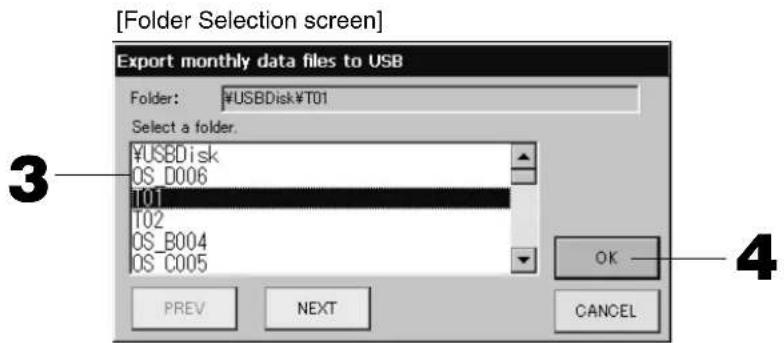
3. Press the folder to be selected.
To change the page, press the PREV or NEXT button.
4. Press the OK button.
A confirm mation screen (Calculating data fi le export confi rmat ion screen / Defi nition fi le backup confi rmat ion screen) is displayed. Press the "OK" button on either of the screens.
Note
- If the CANCEL button is pressed, it returns to the previous screen.
- The "Import a configuration file from USB" button is not needed.
See the bundled CD-ROM for calculating on a PC.
Important!!
Calculating Data
(1) Follow the above procedure to transfer the calculating data to USB memory.
(2) Remove the USB memory from the central control and connect it to a PC.
(3) Insert the CD-ROM that was bundled with this unit into the PC and start the software.
(4) Operate the software according to the CD-ROM menu.
There is no need to have the USB memory connected to this unit at all times.
After installing the calculating data software, steps (3) and (4) are unnecessary. Operate the software with reference to the manual on the CD-ROM.
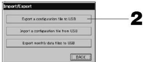
1. Press IMPORT EXPORT button on the MAIN MENU. Page 7
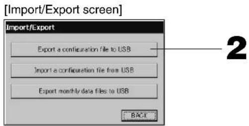
2. Press the "Export a configuration file to USB" button.
Select the folder on the Folder Selection screen. Above [Folder Selection screen]
Note
- If the BACK button is pressed, it returns to the previous screen.
- The "Import a configuration fi le from USB" button is not needed.
By backing up the Defi nition data, the following data can be easily backed up;
- Block and group definities
- Schedule settings
Viewing Alarm History
- Press the ALARM HISTORY button on the SYSTEM CONFIGURATION screen. Page 8 Check the content on the ALARM HISTORY screen.
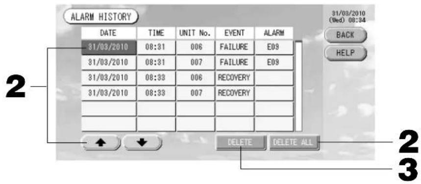
2. Press the date to be deleted.
The date is reverse highlighted. Change the date selection using & &
3. Press the DELETE button.
The selected Alarm history item is deleted.
2. Press the DELETE ALL button.
All Alarm history items are deleted.
- If the BACK button is pressed, it returns to the SYSTEM CONFIGURATION screen.
System Information
The version of the Air-Conditioner Management System being used can be confi rmed. In case of SC-SL3NA-BE, you can confirm the current day's pulse input count from gas meter or wattmeter.
- Press the SYSTEM INFORMATION button on the MAIN MENU.
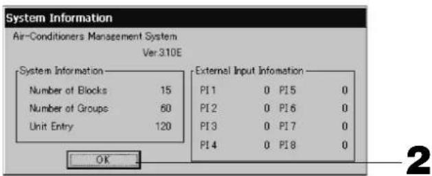
- After checking the content, press the OK button.
System Information display closes.
Help
- Press the HELP button.
Details about the screen being displayed are shown.
Check the content by pressing
- Press the BACK button.
It returns to the previous screen.
Maintenance
Wipe with a soft, dry cloth to clean. When it is very dirty, excluding the touch panel, use a neutral cleanser dissolved in warm water to wipe it off and afterwards wipe that off with clean water.
Caution
Do not use paint thinner, organic solvents or strong acids.
The color may change and the paint may be removed.
Shut Down
The confi rmation screen is displayed after the SHUT DOWN button is pressed on the Main Menu and enter your password ()
(*) Refer to page 6.
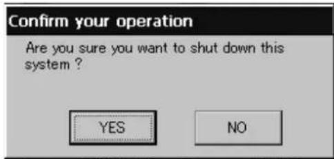
When you press the Yes button, the screen switches to the one shown below (a).
Please wait until you get the message that says "Please switch off the power supply."
When you do not turn the power off, press the No button.
When the screen switches to the one shown below (b), you can turn the power off.

(a)


(b)
Troubleshooting
| A yellow unit icon is displayed. | A malfunction has occurred with the unit. The malfunctioning unit is stopped.Contact the shop where the unit was purchased. The shop will need the following information: "unit icon color", "malfunction situation", "model name of the malfunctioning unit", "Error No. (E00)" etc. |
| A blue unit icon is displayed. A communication problem has occurred.Contact the shop where the unit was purchased. The shop will need the following information: "unit icon color", "malfunction situation", "model name of the malfunctioning unit" etc. | |
| The fi lter sign is lit. Clean the air fi lter.(See the manual attached to the air conditioning unit for the cleaning method.)Press the fi lter reset button after cleaning. | |
| Maintenance display is lit. Regular inspection is necessary.Contact the shop where the unit was purchased. The shop will need the following information: "maintenance display color", "unit model name" etc.*The unit number and maintenance display content can be checked on the UNIT INFORMATION screen. Page 24 | |
| The screen does not change when touched. | It is possible that there is malfunction due to electrostatic discharge. Turn the power off, then turn it on again (power supply reset).When it does not operate normally with the procedure above, it can be assumed that the unit was damaged, so contact the shop where the unit was purchased with the "malfunction situation". |
| No screen is displayed (dark). | The backlight (illumination) is turned OFF after a fixed period of time to preserve the screen. Touch the screen. (It may take a little time for the display to reappear.)It is possible that there is malfunction due to electrostatic discharge. Turn the power off, then turn it on again (power supply reset).When it does not operate normally with the procedure above, it can be assumed that the unit is damaged, so contact the shop where the unit was purchased with the "malfunction situation". |
| The remote controller's display and the unit's screen display do not agree. | When multiple units are registered in a group, the settings for the representative unit for the group are displayed. Check the status display for each of the units. Run/Stop displays "Run" if one or more units in the group are running, and it displays "Stop" if all units are stopped. |
| Air conditioning unit operates on its own. | Check the schedule settings. The group settings that have been scheduled can be changed. Page 20 |
| The unit feels warm to the touch. | The unit may get warm, but this is not a problem.When the room is hot, it gets warm more readily. Use in an environment where the temperature around it is 40°C or lower. |
| The calculating results are not accurate.(SC-SL3NA-BE only) | If the total operating time in a day is less than 30 minutes, there has been no operation for calculating purposes. Therefore the calculating results may be a little low.Even if the air conditioner is not used all day long such as on a holiday, standby electricity is still consumed. If power consumption is allotted to only the operated indoor units on a pro-rated basis, standby electricity consumed on holidays is not included in the calculation result. As a result, the total calculation result becomes different from the actual power consumption. On the other hand, if power consumption of standby electricity is proportionally allotted to all indoor units including those not being operated, the total calculation result coincides with actual power consumption. However, in this case, the power consumption of standby electricity is allotted to not only the tenants actually operating indoor units but also the dummy tenants and the tenants not operating indoor units. This may cause problems among tenants so that this method has not been adopted. If there is any difference between the total calculation result and the actual power consumption, try to reallocate the power consumption to the tenants actually operating indoor units respectively by using the spreadsheet software according to the calculation results. |
| "Importing a confi guration fi le from USB memory has failed. Check the confi guration fi le in the USB memory." message appears. | It is possible that either the defi nition fi le has not been saved to the USB memory or there is an error in specifying the folder to be read. Check again and then perform the operation again.If this message appears again, contact the shop where the unit was purchased. |
| "Exporting a confi guration fi le to USB memory has failed." or "Exporting monthly data fi les to USB memory has failed" message appears. | There is a possibility that the USB memory has damaged or the fi les in the USB memory have damaged. Delete all the fi les in the USB memory and create them again.If this message appears again, contact the shop where the unit was purchased. |
| "USB memory was not found." message appears. | The USB memory may not have been fully inserted. Remove the USB memory, and reinsert it. If this message appears again, it is possible that the USB memory is damaged or the USB memory is not the attachment. Replace it with the bundled USB memory and try the operation again. If this message appears again, contact the shop where the unit was purchased. |
| “SL-0X-self address duplica- tion error was detected.”“ SL- 0X- self transmission data read error was detected.”“ SL-0X- data transmission error was detected.” message appears. | Contact the shop where the unit was purchased. (Re-check the communications line connections of the units.) |
| Error messages other than the above are displayed. | Perform operations according to the messages on the screen or turn the power off and then on (power supply reset). If the message appears again, contact the shop where the unit was purchased. |
| The room temperature display does not change from “--”. | When the intake-air temperature is 0°C or less, “--” is displayed. When it differs from the display of remote controller, contact the shop where the unit was purchased. |
| When you select “Valid” for the Individual Lock/Unlock on the Function Setting screen, the function of permitting and prohibiting the individual operation of the remote con- troller do not work. | This function can be applied to the indoor units, which are the model KXE4 or later, and to the remote controller, which is the model RC-E1 or later. Make sure to select “Invalid” for the Individual Lock/Unlock on the Function setting screen. |
| In case that operating condi- tion of a part or all of air conditioners which are set to a group, does not display. | There may be inadequacy for communication line or the setting of this center console. Please contact the shop where the unit was purchased. |
| The screen of this central control is not returned to nor- mal display even if you press the reset switch. | This may possible that the central control or power system has malfunction. Please contact the shop where the unit was purchased. |
Caution that performing of the monthly calculation (SC-SL3NA-BE only)
- We can not compensate when monthly calculation was not possible by the trouble of this Central Control.
- Because the monthly calculation of power consumption by this data does not conform to OIML, it cannot be applied to public business. And also there are no guarantees concerning the results of the calculations.
- Please prepare the PC, spreadsheet such as EXCEL, a printer, a voltmeter, the gas flow meter that are required for calculation.
Installation
Do not install the central control in any area where noise easily generates.

If it is installed near the computer, automatic door, elevator or equipment which generates noise, it will cause to improper operation.
Do not install the central control in any area where it is very humid or the vibration is large.

If it is installed in an area exposed to humidity, splashing water or high vibration, it will cause malfunctions.
Avoid any place which is exposed to direct sunlight or is near a heat source.
If it is installed under direct sunlight or near a heat source, it will cause malfunctions.
After Sales Service
- Have the following information available when requesting repairs.
Model name
- Installation date
- Problem status, as detailed as possible
- Address, name, telephone number
Repairs after the free service warranty period.
Consult your dealer.
Warranty period is one year from installation. It will be charged when repair is required after the period. Please consult your dealer.
Questions
For after sales service, consult your dealer.
Relocation
Since expert techniques are required, always contact your dealer.
In such cases, there will be a fee for relocation.

3rd Floor Thavies Inn House 3-4 Holborn Circus London EC1N 2HA, ENGLAND
Tel: +44-20-7842-8171
Fax:+44-20-7842-8104
http://www.mhie.com
三菱重工业(上海)有限公司
9C Commercial Road Kingsgrove NSW 2208 PO BOX 318 Kingsgrove NSW 1480
Tel: +61-2-8571-7977
Fax:+61-2-8571-7992
http://www.mhiaa.com.au
MITSUBISHI HEAVY INDUSTRIES - MAHAJAK AIR CONDITIONERS CO., LTD.
220 Lad Krabang Industrial Estate Free Zone 3,Soi Chalongkrung 31,Kwang Lamplatiew,
Khet Lad Krabang,Bangkok 10520,Thailand
Tel: +66-2-326-0401
Fax: +66-2-326-0419
(Gris) Inspection, Inspection 1, inspection 2
(Jaune) Procedure de sauvegarde (inspection 3)
[Fenetre d'importation/exportation]
3rd Floor Thavies Inn House 3-4 Holborn Circus London EC1N 2HA, ENGLAND
Tel: +44-20-7842-8171
Fax: +44-20-7842-8104
http://www.mhic.com
三菱重工业(上海)有限公司
9C Commercial Road Kingsgrove NSW 2208 PO BOX 318 Kingsgrove NSW 1480
Tel: +61-2-8571-7977
Fax:+61-2-8571-7992
http://www.mhiaa.com.au
MITSUBISHI HEAVY INDUSTRIES - MAHAJAK AIR CONDITIONERS CO., LTD.
220 Lad Krabang Industrial Estate Free Zone 3,Soi Chalongkrung 31,Kwang Lamplatiew,
Khet Lad Krabang,Bangkok 10520,Thailand
Tel: +66-2-326-0401
Fax: +66-2-326-0419
3rd Floor Thavies Inn House 3-4 Holborn Circus London EC1N 2HA, ENGLAND
Tel: +44-20-7842-8171
Fax:+44-20-7842-8104
http://www.mhie.com
三菱重工业(上海)有限公司
9C Commercial Road Kingsgrove NSW 2208 PO BOX 318 Kingsgrove NSW 1480
Tel: +61-2-8571-7977
Fax:+61-2-8571-7992
http://www.mhiaa.com.au
MITSUBISHI HEAVY INDUSTRIES - MAHAJAK AIR CONDITIONERS CO., LTD.
220 Lad Krabang Industrial Estate Free Zone 3,Soi Chalongkrung 31,Kwang Lamplatiew,
Khet Lad Krabang,Bangkok 10520,Thailand
Tel: +66-2-326-0401
Fax: +66-2-326-0419
3rd Floor Thavies Inn House 3-4 Holborn Circus London EC1N 2HA, ENGLAND
Tel: +44-20-7842-8171
Fax: +44-20-7842-8104
http://www.mhic.com
三菱重工业(上海)有限公司
9C Commercial Road Kingsgrove NSW 2208 PO BOX 318 Kingsgrove NSW 1480
Tel: +61-2-8571-7977
Fax:+61-2-8571-7992
http://www.mhiaa.com.au
MITSUBISHI HEAVY INDUSTRIES - MAHAJAK AIR CONDITIONERS CO., LTD.
220 Lad Krabang Industrial Estate Free Zone 3,Soi Chalongkrung 31,Kwang Lamplatiew,
Khet Lad Krabang,Bangkok 10520,Thailand
Tel: +66-2-326-0401
Fax: +66-2-326-0419
VOORZORGSGMAATREGELEN VOOR AFVALVERWERKING
(Geel) Reservehandeling (Inspection 3)
(4) Planning
[Scherm GROUP(List) (GROEP(LIJST))]
[Scherm Schedule Temperature Setting]
[Scherm Copy Schedule]
[Scherm Function Setting]
[Scherm Detail Setting (Details instellen)]
3rd Floor Thavies Inn House 3-4 Holborn Circus London EC1N 2HA, ENGLAND
Tel: +44-20-7842-8171
Fax:+44-20-7842-8104
http://www.mhie.com
三菱重工业(上海)有限公司
9C Commercial Road Kingsgrove NSW 2208 PO BOX 318 Kingsgrove NSW 1480
Tel: +61-2-8571-7977
Fax:+61-2-8571-7992
http://www.mhiaa.com.au
MITSUBISHI HEAVY INDUSTRIES - MAHAJAK AIR CONDITIONERS CO., LTD.
220 Lad Krabang Industrial Estate Free Zone 3,Soi Chalongkrung 31,Kwang Lamplatiew,
Khet Lad Krabang,Bangkok 10520,Thailand
Tel: +66-2-326-0401
Fax: +66-2-326-0419
Botão ACCOUNTING PERIOD
(Periode de Registo)
[Ecra Import/Export (Importer/Exporter)]
[Ecra Import/Export (Importer/Exporter)]
3rd Floor Thavies Inn House 3-4 Holborn Circus London EC1N 2HA, ENGLAND
Tel: +44-20-7842-8171
Fax:+44-20-7842-8104
http://www.mhie.com
三菱重工业(上海)有限公司
9C Commercial Road Kingsgrove NSW 2208 PO BOX 318 Kingsgrove NSW 1480
Tel: +61-2-8571-7977
Fax:+61-2-8571-7992
http://www.mhiaa.com.au
MITSUBISHI HEAVY INDUSTRIES - MAHAJAK AIR CONDITIONERS CO., LTD.
220 Lad Krabang Industrial Estate Free Zone 3,Soi Chalongkrung 31,Kwang Lamplatiew,
Khet Lad Krabang,Bangkok 10520,Thailand
Tel: +66-2-326-0401
Fax: +66-2-326-0419
(6) KaTaoTaon movadac
H kataoatao novadac εφaviciετai με εikovec.

Naun owy aalpatos (ia n eipaootepoovadocstauatnoav oywduoitoupyiac.)
Papakaaw EITIKOIVWvnoTe ME TO kataoTma TIO ayopaoate Tn OOUKEun.

Zntnon (To eXepiKo onpa kataxwpeiTai oTO tepaTko ntnonc. 0eia 12)
Koupi ABC: iOaoyta Keepaaio xaapaktnpeC.
Koupi abc: iOaoyovTai TcgojXapaktnpeG.
Koupi 123: iayovtai apiio.
Koupi BS:diypaepi.(Diaypaepi evav apioo).
Koupi SPC: 10ayei daoTma.
Koupiia < > : to oipoe a npoc ta apioTepa n ppoa 日 eoia.
Aioepwoeic oE TepiTTwon diaKoTnC pEuMaTOc
o Tou biatnpouvtai kata n diapkeia iiai diakotnns npoxnis xuos
H diaoppwon ouotnatoC TPO opizetai ot n eAida 8
OpuBuaeic TpoypaumatoC Tou exouv eapauootei ot eia 20
Hpuoian aeitoupyia Tou eapuoOtnke oT eAida 27
- uTioLoyiouou tng katavalwongn 1oxooc eoc tn biakotnpaoxoc (movo yia SC-SL3NA-BE)
nou dev biatnpovvtai kat aTn diapkeia piaac biakotns npoxns ioxuoc
Ouovhke eitoupyiaac kai n pokaopioevn kataoataan kae oawepikns movadac npiv tn diakottnapoxnc ioxuo (ountepiaaamabovoevns tnc kataotaang eitoupyia, ts eimoyng opioou epokpaiaac kain tnc pokaopioevn cataoataangs yia tnv atoboxn n tov atokleio n aeitoupyiac tou thxepiortnpiuK.tλ).
Eav n diakotn Tou peuatoos diapkeoei yia Tepioootepec atro 48 wpc, to eawteiko poloi tha paiyva aeitoupyei kai n aleioupyia tnc kaote omuac deg vthayivei oumuwva te puoipauato. O aptene va puthetaiae TE KA taoi. Se TEPiTTwn Tou n diakotn peuatooc deg diapkeoei TepiooTepo atto 48 wpc, dev xpeiaceai va puthetaiaete gava to poloi kai n evapsn/diaikotn leiotoupyiac kae omuac oivetai oumuwva te tvapakatw kavova.
Otau aokataaota e i npoxn tou peuato, n aeitoupyia ts kaote oadac taakolouthetai tnv nnoiotepnp uthetaion Tou poypauatoc, Tou eixyeivei piv anto th biakottn. Eav dev utnpax av puthetaic otnv nnaiotepn kataxwipion tou poypauatoc, 0aakouhnoe i aedowc nnoiotepnp uthetaion tou poypauatoc.
Eav ekivn yia ekivn tvn npepa dev exovyivei puthetaic, n ouykepiiev n kevtpiKovola dev th a aottei kaveva onma aeoupyiac, o eoioaonote ouda.
Xpónση μνήμης USB
Pnpooxn
I nponyouuva [Obov n EtiIoync qakeou]
Σημειωη
Eav TnnoeTo koupti BACK (NI2), 8a EIOIOTpeyTe Otnv TpOyoUeyn oOvN.
- ev xpeiaeia va xpnoiopoioane to koupi "Import a configuration file from USB" (Eioaywyn apxeiou diaopppwong aTRO kapra mnuhns USB).
H 8nmuopvia avtipapawv aospaleiac twv 8e0oEvwv ka0opioou, tTITpeTTNv Eukoan atoKeuon Tov npakatw 8e0oEvw:
Kaθopiμοι των περίουν και των σαδων
- Puθμεις προγραματος
PpOBoLn IOTopIKoU TPOEIOIoiNcewV
Eav TnOeTo KouPi BACK (NIU, 0, 0, 0, 0, 0, 0, 0, 0, 0, 0, 0, 0, 0, 0, 0, 0, 0, 0, 0, 0, 0, 0, 0, 0, 0, 0, 0, 0, 0, 0, 0, 0, 0, 0
3rd Floor Thavies Inn House 3-4 Holborn Circus London EC1N 2HA, ENGLAND
Tel: +44-20-7842-8171
Fax:+44-20-7842-8104
http://www.mhie.com
三菱重工业(上海)有限公司
9C Commercial Road Kingsgrove NSW 2208 PO BOX 318 Kingsgrove NSW 1480
Tel: +61-2-8571-7977
Fax:+61-2-8571-7992
http://www.mhiaa.com.au
MITSUBISHI HEAVY INDUSTRIES - MAHAJAK AIR CONDITIONERS CO., LTD.
220 Lad Krabang Industrial Estate Free Zone 3,Soi Chalongkrung 31,Kwang Lamplatiew,
Khet Lad Krabang,Bangkok 10520,Thailand
Tel: +66-2-326-0401
Fax: +66-2-326-0419
MEPbI PPEOCTOPOXHOCTN PPNYTNJIN3AUIN

Ha BaaeHTpaBbHnIyPbAeHHeMooKet 6bIb HaeceHa TakaH MapKnpoBa.3oO3hauaet,HTo nDnEkaueyeTynlnaaun 3eKtpueckne 3neKTPOHbte KOMHOENTb (corNacho paoRjKeHHIO 2002/96/EC o63NaHauoJmeC8 a66peBaTuPOW WEEHE He dONKbI CMeuBAtcBc C o6iIM Xo3nCTBeHHbM MycOp. CeHTpaBbHnIyNtypaBHeHn OndexyTynlnaaum B cneuaJIbHO npedHa3NaeHHbIX DnIe 3TO rNkTx (noTobPHOr HO NcNoB3OBAHN, NepebaOTK, BOcCTAHOBHeHn), daHHeO yTPOCTBO He dONKo NOnaadB O b6UO Maccy Ropodckx OTXoOB. Boone noDpOHy IHfOpMaun Bbl MoKTe NOyUnr, 6opatNBmCB B fIPMBy-ycTAHOUsIK INI K yONHOMOHHeHbIM Ha MeCTAX.
3TOT CIMBOI, HaneaataHbHn Ha 6aTaepex, npnaaraembIX K eHTpaJIbHOMy NylbTy ynpabHeHnRABJIeTCR INHOpMaueN dN KOneHbIX NOnb3OBeTeNe, cornacho DneKtne Ebpocoi03a 2006/66/EC, cta7b 20, npnoKeHne II.
BaTapeH NO OKOHauHHo cpoKa CnyKbI DOJIxHb6bITbYTIN3NHPoBAHbOT DeJIbHO OT O6uX 6bITOBx OTxOob.EcIM XMMueckn CMBON HaneataH HIXe YkazahHO BIIWE CMBOnA, TO 3TO XMMueckn CMBON O3Haayet, YTO BaTapei COpeJxAT B ONpeJeHHO KOHcHTpaM N TAnEble MeaJIb. 3To 6yTe 063aHHeHO KAK NOKa3aHO HNG:HpTyb(0,0005%), Cd:KaDMn(0,002%), Pb:cBmHe(0,004%)
TOnaIyIcTa, yTnH3npYte 6atapen HauJnxAaMm Opa3OM B MeCTHOOPraHn3aMn NO BBIO3y OTxOoB NIN B CEHTpe nnopepa60Te OTxOoB.
MepbI npeIoCTOpOxHocTn
- IpeepnHcnoJb3OBAHnue cHTpaIbHOro npIbTa ynpaBHeHn, BHNMaTeIbHO npOHTaTe HactOurne "MepnpeoctopoxKHOt" nObeCneeyHnHaJIeKaSeE 3KcNpyaTuu yCTpoCTBa.
- Меры пedingосторожнocг КлассицуOTс no KaTEROPHm ONACHOCTB" n "OCTOPOXH O". Меры пedingostорожнocг, пINBEeHHbE B KOLOHKe "ONACHOCTB" yka3bHaOT Ha To, YTO HENpaBnIbHOe obpaueHne c yCTpoIcTBOM MOKET pINBeCTN K cepbe3HbIM NOCNEdCTBnAM, HanpIMep, K CMEPTN, cepbe3HO TpaBMe, n T.I.
Pn 3TOM, OHaKO, DaKe Te Mepbl PpeOCTOPOXHOCTH, KOToBle PpNBOaTc B KOHOKE “ OCTOPOXHO”, MoryT NMeTb cepbe3HbIe NocneCTBnR, B 3aBNCIMoCTN OT KOHKpeTHbIX o6ctOaTeNbCTB. IoxaanyiCtA, cTporo co6hDaIte daHHbIe MepbI ppeOCTOPOXHOCTH dnn ObecneueHnBaew nHou 6e0NaChOCTn.
CmBOLnka,ncnoJIb3yEmaB TEKCTe daHHoro pyKOBOdCTBa,IMeET cneDyIOue 3HaueHne.

CtporoBocnpesaetca.

Ctporo co6nOaTe HNCTpyKun.

ObecneytheHaJIeKaUee3a3emJHeH.
- Iocne 03HaKOMnHnA C daHHbIM pyKOBOCTBOM NO 3KcnNyaTaun, NoXaanyCTa, CoxpaHnte erO B DOctynHom MecTe nIy6dyuux cnpabok. PnCmeHe onepaTopa, KOTOpB paobTaet C obopydoBaHnEM, Oba3aTeNbHO nepeaTe emy daHHoe pyKOBOCTBO.
IMEPbI INPEOCTOPOXHOCTN IPN YCTAHOBKE
ONACHOCTB
UeHTpaBHyI npbIy npaBHeHn DOJxH yCTaHaBJIbA TbCBn IInepom, y KOTopoR O Bbl npno6peHn o6OpydoBaHne, nKBAHnHnPcHPOBaHHbIM CnEuaNtOM NO yCTaHOBKe.

He pekomeHnyetcyaTaHaBnBaTb ceHTpaBHyI npbl TynbT ynpaBHeHc CamOCToTeNbHO, NockoBky HnPaBnBHOe ObaueHne C Hm MOxET npBecTn K nopaxEHIO 3NeKtpnueckHM TOKOM IIN BO3NKnHOBeHIO NOxapa.
OCTOPOXHO
063aTeIbHO BbINOJHnTe 3a3EmJeHne. B 3aBcHmOCTn OT MecTa yCTaHOBKn, MoKET

He noDcoeINHnIte 3a3emNIAIOuN Ka6eJIb K ra3OBbIM nIN BDOJPOBOIDhBIM TpyBaM, K MOHNEOTBOdAM nIN K npOBoAM 3a3emJeHnTe TepeHOB. HeoCTatoOHoe 3a3eMJIeHne MoKeT npVBecnK npaKeHHIO 3NeEKTpuYeCKm TOKOM.
NoHaObntbca HcNOJIb3OBaHHe aBTOMaTHueCKOROBblKIOUaTeJIyTEuKN.

EcnnnabTomatnueckm BbIKIOuateIb yTeKN He yCTaHOBHeN, MoKET npOn3OHTn nopaxKeHne 3NEKTPOTOKOM. O6paTnTEc b K dInepy, y KOtOporo BB npNo6pei NOBpyoBaHne.
I MEPBI INPEDOCTOPOXHOCTN IPN PABOTE
ONACHOCTB
Ecni ceHTpaIbHbI nyIbT ynpaBHeHH, BcJIeCTBne npnpoDHorO 6eDCTBnA, HAnpMep, HABOnHeHH Nm TaYHa, 6bl NOBpeKdEh BODo, ObaTntecb K DInJepy, y Kotoporo Bbl npno6penn o6OpydoBaHne.

Pa6Ota C cHTpaJIbHbIM nIyIbTOM ynpaBJIeHNBA TAKINX YCIOBnAX MOKeT pINBEcTN K NOIOMKe, nopaxHeNIO 3NeKtpUneCKM TOKOM IIN NoxApy.
Ecnn yctpoicTBo nonano noB 03deiCTBne HENOpMaIbHbIX ycNOBn, npeKpaTnte erO 3KcNpyatauIO, OTKNIouHte 3JIeKTPoNTaHne N o6paTntecb K dInepy.

IpoDOnJKeHHe 3KcNpyaTaun ceHTpaNbHorO npbTa ynpaBnEHH B TaKnx ycNoBnX MoKet npNBecT N NOIOMKE, npaKeHHIO 3NeKTPnueckm TOKOM n/nnnoxapy.
OCTOPOXHO
He pa6oTaIe cycTpoIcTBOM,ecn y Bac MOKpbie pyKn.

TO MOKTe npBcTeN K nopaxKeHIO 3NeKtpnCheKIM TOKOM NIK NIOJONiMeK.
He TaHHTe 3a Whyp nTahn.

ПиТОСЕДИЕМИshура MOKETпpon30TN KOPOTKOE 3aMbIKAHMe.
3anpeaetcMbITb ceHTpaJIbHbI nylbT ynpabneHn BODo.

3TO MOXET npBECTN K npaKeHENIeKETPNHeCKM TOKOM NIK KAbpAM.
OTBOD cTaTHueCKOrO 3JeKTPuYeCTBa Ypee3 6JIOK MoKeT PnIBEcT N KNoIOMKe.
Ipeed hauanom pa6oTb KoCHHTecb 3a3emnEHORo MetaannueCKoro ObekTa dJa OTBODa CTaTNueCKOrO 3NeKtpnHeCTBa.
Ecnn3Kpaan yacto "3aBncaet, peKomeHdyETc npcoeHNHTb aHTNCtataueckn nIcT nn anahaoNHyb npeDMet.
MEPbI PPEIOCTOPOXHOCTN IPN N3MEHEHIM MECTONOJOXEHHN IIN PEMOHTE
ONACHOCTB
HnKOrda He n3MeHnTe He pa36npaTe ceHTpaIbHbI nyIbT ynpaBHeHH. EcHn Heo6xOdmo 06cnyXnBaHne, o6paTntecb K dJIepy, y KOtOporo Bbl npno6peHn o6opydoBaHne.

HehaJnEkauee 06cnyKuBaHne MoKeT npBecTn K npaxKeHIO 3NeKtpueckm TOKOM n/nnnoKapy.
Ecnn Heo6xOIMO nepemeueHne ceHTpaIbHoro npIbTa ynpabLnHn, 6paTntecb K dnlpepy.

HenpaBnBHa yctaHObKa ceHTpaBHorO nyIbTa ynpaBHeHMA MoKET npBecT N nopaxKeHIO 3NeKTpueckm TOkOM W/IN NoXapy.
Pacuet 3hepro3aPat dna daHoro np6opa He COOTBeTCTByeT HopMaM MekdyHapOHO opraHn3auu 3akoHdaTeJbHo MeTpOJorHn (OIML), no3tomy npabNbHocTb pe3yJbTaTOB COOTBeTCTByIOx npacetob He rapaHTnpyETc.
DanHbI np6op paccHTbIaet ToIbKO paCnpedeJeHne 3Hepro3aTpaT (ra3a, 3NeKtpo3HeprH). Bam HeoXoIMo paccHTaTB Ko3ΦmUeHTbl KOHNIOHnPOBaHn BO3dyxa.
BhimaHne!
TOT np6op OTHOCHTCA K KJIACcy A. B 6bIty HAcToaun np6op MoKeT Bbl3BaTb paAnonomexn. B TaKOM cnyae Notpe6nteIO MoKeT 6bITb Heo6xOdmo pInHrT COOTBETCTBYUOne MEPbl.
В级以上
0630p
LcHTpaIbHbI nyIbT ynpaBHeHn CnyKNT dIy npaBHeHn BHyTpEHmM MoyIaMn KOHdIuOHePob. Bce Oepaun, TaKe Ka KOTpoJIb yCTpOJCTBa, peXIMbl paOtbl, HAcTpoIKN COCTaBJeHne pacINcaHn, MOrYT BbINOJIHrTaC Ha CeHCOPHO NaHII.
Ha3BaHnI ΦyHKcnn 3JIeMeHToB
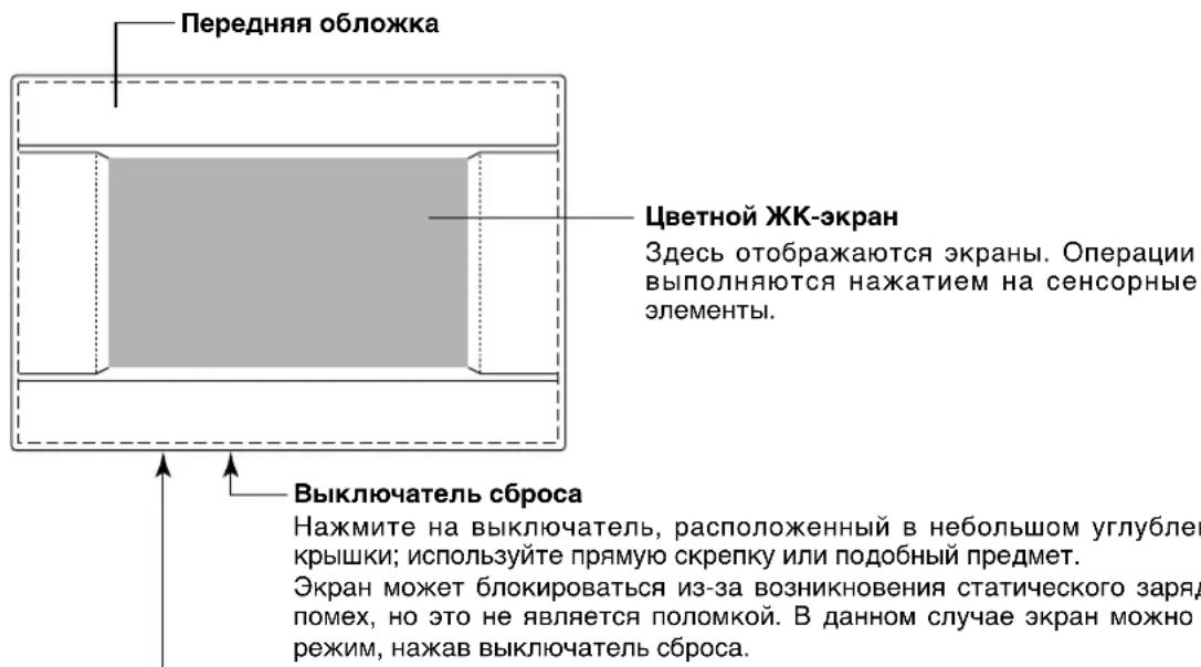
Pazbem narnTn USB
PamTb USB BCTaBJIeTc CHN3y.
BhimaHne!
He bCTabJIte dpyIne ycTpoIcTbA USB, OTmUHbIe ot "nakTeHoi" nAmrTu USB (bundled USB memory).
Блokи, рурпbli
[πpimepbI coeHHeHH]
![MITSUBISHI SCSL3NAAE - [πpimepbI coeHHeHH] - 1](/content/2026/03/428779/images/718b82e1b8714ce80c2f8a33eab18ad75bb2c06763feb6c3583a385399d1603a.jpg)
B Ody rpynny moxHO Ha3HaHTb MaKcMym Do 16 yCTpoiCTB KOHNIOHINPOBaHH.
He nCnoB3yIte OINn PyIbT dNCTaHcNoHHoro ynpaBneHnA dna pa3nHbIX rpynn ycTpoiCTB KOHNIOHOHPOBAHn BO3dyxa.
B OdINH 6nOK MoKHO Ha3HaHTb MaKcMym Do 9 rpynn.
- MoXHo Ha3HaunTb MaKcMym 16 6IokOB.
R :Пиьт ДИСТаHCUINOHOrO ynpaBJIeHnA
![MITSUBISHI SCSL3NAAE - [πpimepbI coeHHeHH] - 2](/content/2026/03/428779/images/f8cd6d1fbfbabc2df30860fb21f1f178be5c8a2e6bc97b07b63f22f8189a815a.jpg)
HaçaλbHbɪŋ əKpaH
[HaayaJIbHbI 3KpaH]
[IVHΦopMaunOHbIy 3KpaH]

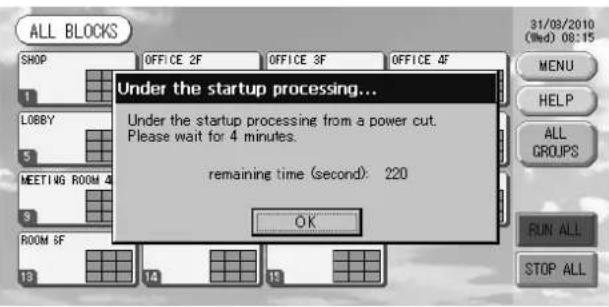
DaHHbI 3KpaH OTo6paXaTcPn HauJIpe pa6Obl.
euaHne
Yepe3 HnpoDOnXnTeJbHoe BpMa NOBnHeTcB Bo BpMa OTo6paKeHHaN HOpMaunOHoro 3KpaHaCJeNyUoIy3KpaH. BBOd HaCTpoE KHeBO3MOKeH.
- 3кразн ALL GROUPS (BCE Гупbl)
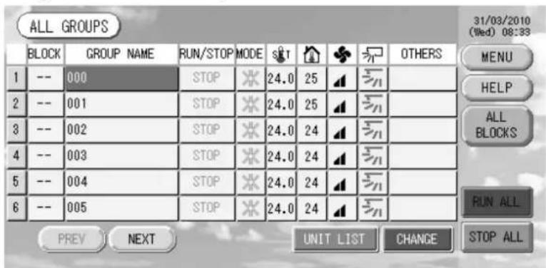
3TOT 3KpaH NOBnAETc npn nepbOM 3anycke yctpoiCTBa nIn B TOM cnyae, ecnn 6noK He 6bl 3aperntpnpoBaH. BInOJIHnTe nepBOHaaIbHbIe HAcTPOkN B CneDyUoSe IocNeIOBaTeNbHOCTn.
HactpoKa BpeMeHH n DaTbI cTpahnua 11
OnpeJeHne rpynn cTpaHnua 11
Onpeenenehe 6nokOB cTpaHua 13
*Udo6cTBo pernctpaun 6JOKOB COCTOHT B TOM, YTO INHOpMaun O COCTOHN BCex rpynn MOxHO npocmatpnbatb Ha OJHOM 3KpaHe.
- 3кразн ALL BLOCKS (BCE БлOKи)
IocJIe BbIOJIHeHnpeRNCtpaun6ILOKOB IOBJIReTc3TOT 3KpaH.
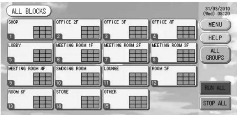
PnmuHaHne
Bo3MOxH, yTo dIa CHTbBAHnHaCTpoe K yCTpOuCTBOM nOTpe6yETc HekOTOpoe Bpem. He npictynate K pa6ote, noka HacTpoeHHbIe rpynnbI He OTO6pa3rTaDOnXhBM o6pa3om. (To DoJxHO 3aHrtb NIIb HECKoJIbKO MInHyT.)
CnpaBoHna Ta6nua onepaun
(3eJIeHbI) OCTaHOBJeH (PnOCTaHOBKe BCEx yCTpoiCTB).
(KeIbI) HenCnpaBHOCTb OJHOro ININ HeCKOJIbKnx yCTpoiCTB.
(cnnn) Oun6ka kOMmyHkaaun (oun6ka npn B3aHMOeJCTBUN COnHM INHeCKOJIbKIMN UcTPOUCTBaMn).
(2) 3HaOK qInbTpα
3TOT INHINKATOP 3aropaeTc, ecnn, KaK MNHMym, IJN ODHORO n3 yCTPOYCTB KOHNIOHOPOBAHNA BO3dyxa B 6I0ke nn rpynne, Tpe6yeTc texHueckoe o6cnyxHBaHne fInbtpa. Ecn 3TO npOn3oJdET, BbINOHNHTe YNCTKy fInbTpOB.

AbaHnBIOCTaHOB (BHeHnCnHaJ BBOITcA Yepe3 KEmMy abapHOrO octaHOBa.)
Bce noKIOHHe 6nOK OCTaHaBnBaOTc, paOta 3anpeueHa. Korda cnHrAaBapnHorO OCTaHOBA OTMeHReTc, npaMeTp ydaJIeHHoro KOHTpOnIepa 6nOKnpOBKn/pa36nOKnpOBKn MeHReTc Ha o6paTHbI, Ho 6nOKo OCTaOTc octAHOBJIeHHbIM. Ecn HactpoKa rpaqNka BblnoJHeHa, 6nOK NaHnHaIOT paObaTaB corNaCHO yCTaHOBNeHHOMy rpaqNky.
3KpaH IOdTBepXdEHHa NepeKJIoueHHa

3TOT 3KpaH RnE Tc NOITBepXdEHm N3MeHeHn pa3NHybIX npaMetpoB. OTo6paXaEmbI Ha daHHOM 3KpaHe TEKT 3aBNCIT OT Ha3BaHnR 3KpaHa, a BblONHEmble 3Decb ONepaun ONnCaHb Hxke.
HaxmTe KhoNky "Yes" (Ja) dna coxpaHeHnHaCTpoeK n BbIXoJa. HaxmTe KhoNky "No" (Het) dna BbIXoJa 6e3 coXpaHnHaCTpoE.K.
Функциноюразионе
BHMaHne
Pa3pRd cTaTnueckoro 3neKtpnuecTBa Ha yCTpoNCTBe MOxET npNBecTN K NOJOMKe.
IpeH hauJom pa60Tb I KOCHITcB 3a3eMJIeHHoro MeTaIIINueCKoro O6beKtA, YTO6bl CHrTb 3apJd CTaTIueCKOrO 3JIeKTpUYeCTBa.
HacrtpoiKa BpeMeHn I daTbI
- HaxmTe KhoNky MENU (MEHIO), a 3aTeM KhoNky SYSTEM CONFIG. (HACTPOIKA CNTEMbl).

- Ha 3kpaHe "SYSTEM CONFIGURATION" (HacTpoIka cncTeMbI) HaxMnte KhoNky TIME&DATE SETTING (HACTPOIKA BPEMEHI N DATbl). CTpaHnca 8
[3KpaH HactpoiKn BpeMeHn DaTbI]
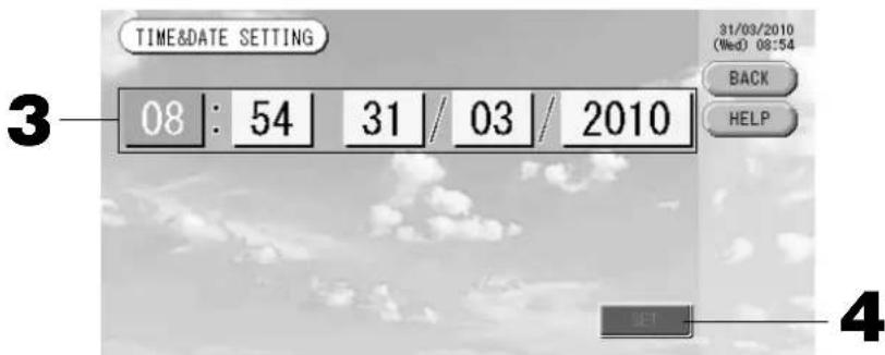
- HaxmTe KhoNKe "Year" (ToD), "Month" (Mecu), "Day" (DeHb) n "Time" (BpeMa).
BVeIte TeKyuO DaTy u BpeMa. CtpaHua 26
- Haxmte KhONky SET (YCTAHOBITb), a 3aTe Ha 3KpaHe noDtbepXdHn KhONky "Yes" (Ja).
Yka3aHHbIe 3HaueHnI dIaTbI IN BpeMeH 6ydy T yCTaHOJIeHbI, a OTCuET cekyn HaNeTcR C "00".EcNn Bbl He XOTHe, YTO6bI daHHa YCTaHOBkA 6bIa BbINOJIHeHa, HaxMNTe KhONky "No" (Her).
PpimMeaHne
-Прин Нжати Кноги BACK (HA3AД) BBINOJIHЯТСВОЗБРАК T 3крану SYSTEM CONFIGURATION (HACTPOИKA CNTECTMbl).
- Ecni OTKIIOHHe NITaHnOcUeCTBnRETC MeHee YEm Ha 48 YacOB, nepeyctHaBaBnBaTb DaTy I BpMa HET Heo6xOIMOCtN.
OnpeJeIeHne rpynn
① Bb6op rpynn dny onpeDeneHn n OTo6paXeHn 3aperncptpnpoBaHHbix yCTpOuCTB
- B rnaBHom MeHNo HaxMnte KhoNky SYSTEM CONFIG. (HACTPOIKA CNTEMbl).CTpaHnca 7
- Ha 3kpahe "SYSTEM CONFIGURATION" (HactpoynKa cnctembl) Haxmnte KhoNky GROUP DEFINITION (ONPEDEJEHNE rpynn). ctpaHnca 8
OTo6pa3ntcA kpaH "GROUP DEFINITION" (OnpeJeIeHne rpynn).
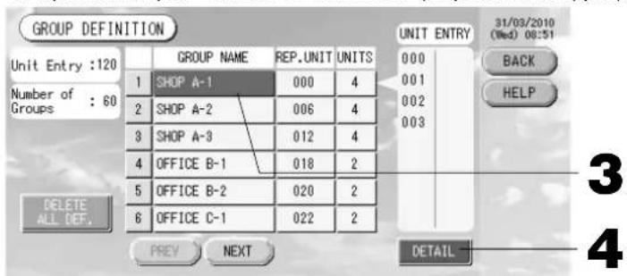
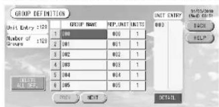
[3KpaHnHaayabHoroOppeJeHnIpynn]
Pepbohaayabhny 3KpaH GROUPDEFINITION (onpepeenehe npnn) MOKeT MeHaTBcB B 3aBnMoCTN OT MeToJa nepeJa.
(PππμεmρπIπ πρeMbduηe yctaHOBK)
No cbbJkn aDpe yctpoNCTBa
3. Bb6epute mma rpynnbl.
Pn do6abHnn HOBn rpynnb Haxmnte ncyto 0bnactb mHeHrpynnb. IaHm3MeHnna papaMeTPOB 3apeHCTpnpoBaHHo rpynnb Haxmnte mHrpynnb. Byet BbcBceHo mH BbIpaHHo rpynnb. IaepexOda co cTpaHnCuHa cTpaHnCu HaxmnTe KhONky PREV (PPE.D.) nnN NEXT (CJIeD.).
4. Haxmte Khonky DETAIL (CBEDEHNA).
Отобразсгэн "GROUP DEFINITION DETAILS" (Сбений о назсанупь).
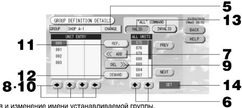
② Perictpaunn nImMeHHeNn mEny yTaHaBnBaemr rpynnbl.
5. Haxmnte KhoNky CHANGE (H3MEHHTb).
BVeIte mRpynnbl.
cTpaHua 26
EcnBbINONHtB HAcTPOkHy He HyxHo, HaxMnTe KhONKy "No" (HeT).
- Haxmte naHeIb rpynnbl, IIN KOTopoONpeJeHIOCTHaCTPOKNBHOCTCAHMeHeHHA.
Pamka nanei CtaHcTne.
- Haxmte Khonky CHANGE (N3MEHHTb).
OTo6pa3ntcAekpaH OCHOBHO HAcTpoKn rpynnbl. Iprn n3MeHeHH 3KpaHa HN OOnH N3 npaMeTPOB ehe He BbI6paH (napaMeTp Tempepatypbl IMeet Nyctoe 3NaueHne). OnpeJeNTe HAcTpoKn TOnbKO dIra Tex npaMeTPOB, KOtOpbie Heo6XODMO YCTaHOBHTb INI N3MeHHTb.
[3KpaH OCHOBHbIX HAcTpoEk rpynnbl]
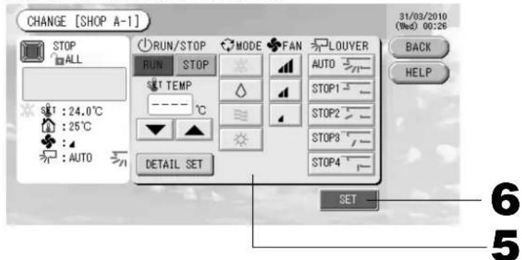
[KhONKa aBtOMaTnueCKOro pexKmAbkIIOUeHa B HAcTpOKeФyHKuIn]
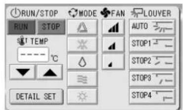
DaHnaФyHKnM MoKet 6bITb npImHeHa K BHEuHM YcTPOiCTBAM, KOTOpBe OTHoCtCR K OXaJkaDaiUIM/HarpeBaIouIM ycTPOiCTBAM cepH He3aBucmBy MynbTu-KXR, GHP-R IIN60one No3dHnx n PAC.
- Haxmte KhONky COOTBeTCTByoUe r npaMeTp a Ira er o HactpoKn nnn n3MeHeHH.
3anyck/octahOB: Haxmnte KhoNky RUN (3ANYCK) uH STOP (CTOJI).
Ipn HaxkTu Ha KhoNky RUN (3ANYCK) cyHKuOnHnpOBaHne HaunHaetc, a npn HaxkTu Ha KhoNky STOP (CTO) cyHKUOnHnpOBaHne ppeKpaTaTc.
- Hactpoia TemnepaTypb: Haxmua ann
YctaHOBtTe TemnepaTpy MeKJy 18^ n 30^
PexnHaxab KhoNky, Bb6epnte Auto (ABtOMaTneckn), Cool (OxnaKdHeNe), Dry (Cyka), Fan (BeHTnIaIu) nI Heat (OborpeB).
- ABTomatueckn peKIM MOKeT 6bItb BKJIIOueH B HaCtpoIke ΦyHKU.
CTpaHua 27
CKOpocTb BpaueHnBcHTnIaTopa: BbIepeNtE aI, aI, nHaXmTe Ha COOTBeTCTByIOU KHOIky.
MOXHO BKNIOHTB B "Function Settings" ("NapaMeTpbI cyHKmN").
HapabJIeHHe Bo3dyxa: BbI6epuTe Auto (aBTo), stop 1 (ocTaHOB 1), stop 2 (ocTaHOB 2), stop 3 (ocTaHOB 3) nIIN stop 4 (ocTaHOB 4) n HaxMnTE KhoNky.
BLOK pa6oTaet C MaKcImaJIbHOH cKOpocTbIO BEHTUNAToPA.
- Haxmnte KhONky SET. Ha 3kpAhe noTBePxxHnHaXmTe Ha KhONky "Yes" (Ja).
Ecnn Bbl He xoTnTe coxpaHrTa 3Tu npaMeTpbl, HaxMnTe KhONKy "No" (HeT).
HactpoKa/ImMeHeHne npaMeTpOB Ha 3KpaHe CBeDeHn o rpynne.
C nomoio 3Toro 3KpaHa MoKHO 3anpeTntBbIIOHHeHne Oepaun C npbTa NCTaHIOHHO ynpabHeHn HcPOCTb HaCTpoKn DnIbTpHa. Ha 3KpaHe "BASIC GROUP SETTINGS" (HactpoKa ochoBHO rpynnbl) HaxMnte Ha KhoNky DETAIL SET (YCTAHOBKA CBEDEHN). Bbiue
Отобразсгд Зкран "DETAILS GROUP SETTINGS" (С蜱едения насторikу рупь).
[3KpaH cBeHeH NAcTpoEk rpynnbl]
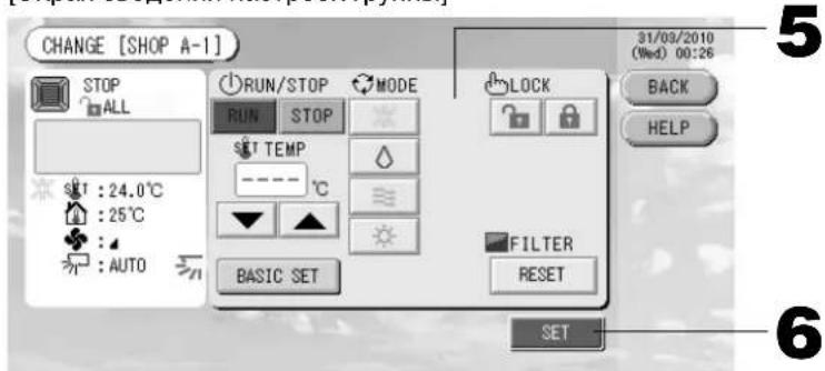
[HaCtpoKa HnDnBnDyanalbHcN6loKnpoBKn/ pa36noKpOBoKn Ha 3KpaHe HAcTpoKn yHKu]
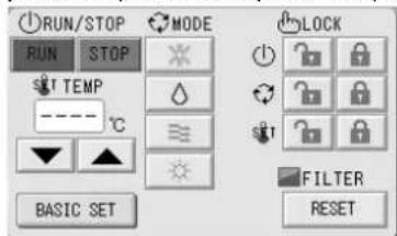
3TaФyHKnI npImeHMa TOnbko IINBHyTpEHnX yCtpoNCTB KXE4 nnn 6OJeeHOBOI MOENI INIpyNbTA DnCTAHNOHOROynpaJIeHNRAcE1 nnn 6OJee HOBOI MOENI.
-
Haxmte KhONky COoTBcTcByUoIero npaMeTpA dIe erO HAcToPouK uIN N3MeHeHHa.
-
NapaMeTpbl 3anycka/OctaHOba, HAcTpoKn TempepaTypbI n peXmHa HbJIOTc TaKIMn JKe, KaK Ha 3kpaHe "BASIC GROUP SETTINGS" (OchOBHaHacTpoKa rpynnbl).
-
LOCK (БЛOKИРОВКА): HabtmTe nJn
EcnnaHaxaTb , onepaunnybTa nucTaHnOHoro ynpabneHn pa3pewaOTc, a ecnn HaxaTb - 3anpeaaOTc.
-
FILTER (ФИльТ): ecnн haжka T Khoнka c6poca, 3haoyk Фильтpa BbIKIOuyeTcR.
-
Haxmte KhoNky SET. Ha 3KpaHe noTBePxxHnHaXmTe Ha KhoNky "Yes" (Ja).
Ecnn Hactpoynky nnn n3MeHeHne BbINONHaTb He HyXHo, HaxMnTe KhoNkY “No” (HeT).
TpimmeaHne
-Пи Нжати На Кногу BACK (HA3AД) Вьлолнэтсь BOЗВрат к п徝ыдушему 3кразу.
- Ecnn Ha 3kpane "Function Setting" (HactpoKa cyHKn) BKIOUeHa cyHKn6bOKpOBKn/pa36bOKpOBKn OTdEBhBx ONepaun, NOBnETcR B03MOXHOCTb pa3peuNTb INI 3anpeTb ONepaun nylbTa DCtAHNOHHORO ynpabNEHn DnA OTdEBhBx 3nEMeHTOB, a TaKxe dIra KaKdoi ONepaun 3anyCKa/OCTaHOBA, yCTAHOBKn peKIMn HAcTpOKN TemNepaTpybl.
- Korda Ha 3Kpahe "Function Setting" (HacTpoKaФyHKcN) pa3peWeHbIФyHKcN 6nOKnpOBKn/ pa36JokpOBKn, onepaunnybTa nCTaHcuHHoro ynpabLeHn 3anpeeHbI, ecnn dJIr BceX onepaun 3anycka/OctaHOBa, yCTaHOBKn peKmHa HacTpoKn Tempeatypbl yCTaHOBHeh 3HaQk . (HeKOTopbIeФyHKcN, taKe KaC6poc 3NaUkaΦnNbTpA, pa3peWeHbI.)
CneIyUoI MeToD MoXHO TaKKe IcNoIb3OBAbT dNn HAcTpOoi NmMeHEnn Oepaun DnN KaKDoIpyPiBbl.
HacTpoIKa IINI IN3MeHeHne HAcTpoEK Ha 3KpaHe GROUP (LIST) (PpyPiA (CnICOK))
- Haxmnte KhoNky GROUP LIST (CINCOK rpynnbl) Ha 3kpahe GROUP (PANEL) (rpynna (IaHEJIb)). CtpaHua 15
IorBntcAekpaH GROUP (LIST) (PpyPiA (CINCOK)).
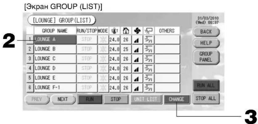
- Haxmte nMa HactpanBaemOn nn N3MeHReMoR rpynnbl.
IIMy Bb6paHHo rpynnb BbICBeuBaEcB INHBePCHOM peKmE. Ia nepeXoJa co cTpaHnCbHa CTpaHcy HaKMITE KONky PREV (IPED.) uN NEXT (CJIEN).
- Haxmte KhoNky CHANGE (N3MEHHTb).
OTo6pa3ntcAkpaH OCHOBHn HAcTpoKn rpynnb. BblOnHnTe HacTpoKy nIn nImeHnI.
CTpaHua 16
PpMMeaHne
- Ppi Na KaTn Ha KhoNky BACK (HA3AД) BbInonHReTcB O3BpaT K ppebldyuemy 3KpaHy.
Pa6oee coCTOHNye yka3bIbaETcA, ecn, no KpaHne Mepe, OJHO u3 yCTpOHTB cyHKUHOHPyET. HenCnpaBHOe COCTOHNye yka3bIbaETcA, KOrDa, no KpaHne Mepe, OJHO yCTpOHTBO HaxOHTcB H HenCnpaBHom COCTOHN. CoCTOHNye OCTaHOBa yka3bIbaETcA, KOrDa pa6Ota Bcex yCTpOHTB OCTaHOBNeHa.
3NaO K OTo6paKaetcKoTda, no KpaHHe Mepe, nIa OndHO n3 yCTpoNCTB TpeByeTcNCTka.
3NaOy OTo6paXaETc, KOrda, no KpaHne Mepe, IIn oHoro n3 yCTpOJCTB Tpe6yETc Texo6cIyXuBaHne.
PexnM cyHKUHOHPOBaHN, HAcTpoNka TempeaTpybl, TempeaTpaB nOmeeHN, CKoPoCTb BEHTIaTopa HAnpaBHeHne BO3dyxa OTo6paKaOTcDnA pepe3eHTaTNBHorO yCtpoiCTBa.
- 3IeMeHTbI, oBeHeHbIe opaHKeBO paMKo, OTHocTcK OnepaunrM, BblONHeHne KOTopbIX C nylbTa DnCTaHIOHO ynpabJIeHn 6blIO 3anpeUeHO B HAcTpOuKaX rpynnbl.
- Ecni naxaTb KhoNky GROUP PANEL (IaHEJIb IpyPibl), noBntc 3KpaH GROUp (PANEL) (IpyPiA (IaHEJIb)). CtpaHnca 15
Hactpoika nn n3meHeHne napametpoB Ha 3kpahe "ALL GROUPS" (BCE FPYINbl)
- B rIaBHOM MeHIO HaxMnte KhoNky ALL GROUPS (BCE PPyNbl). CtpaHnca 7
- HaKMnte KhoNky c mHeHem COOTBeTCTByIoUe IpynnbI dJa ee HAcTpOuKn NIn N3MeHeHHa.
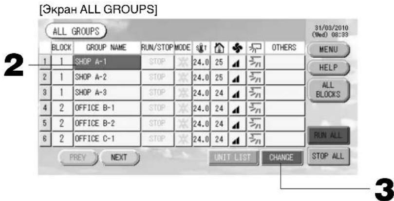
BbTe BbICBeHcHbBb6paHHo rpynnbl.
Ipi nepeeknIOeHnn 3KpaHa 6ydt BbIbpaHa paHee BbIbpaHHa rpynn. IInn nepexoDa co cTpaHnCbl Ha cTpaHnCy hXKMnte KhoNky PREV (IPED.) nn NEXT (CJIEN.).
3. HaxmTe KhOnky CHANGE (U3MEHHTb).
OTo6pa3ntcA3kpaH OCHBHO HAcTpoKn rpynnbl. BbInOnHnte HAcTpoKny nIIN N3MeHeHNA. TpaHnca 16
PpIMeuaHne
-ДяоTO6paXeHЯуCTpoHCTBВrpynneHaXmTeKhONky UNIT LIST (CINCOK YCTPOYCTB).
CTpaHua 24
-ДягOTOBpaKeHЯ BCEx 6JIOKOB HaxMnTe KHOnKy ALL BLOCKS (BCE BLOKN) CtpaHnua 9
- 3IeMeHbI, OBeHeHbI opaHKeBO paMKoI, OTHocTcK K OpeaunM, BblIOJIHeHne KOtOpBX C NylTa DnCTaHIOHOrO ynpabNeHn6blno 3aIpeUeHO B HAcTpOikax rpynnbl.
- Пин haхатуни на конь MENU (MEHIO) уdent oToobpaxeRoIabHoe MeHIO. CtpaHnca 7
YcTaHOBKnpeXnMa pa6Otbl HeCKoJbKnx rpynn
B 3TOM pa3dene noka3aHo, KaK ynpabTb HeCKoBkMn rpynnamn B OJHOM 6JIOke.
- B rIaNbHOM MeHIO hAXMnte KhoNky ALL BLOCKS (BCE 6JOKN).

- Haxmte 6nok, nra KOTOPORo Heo6xOIMO onpeJeHtB hAcTPOJKn.
Повитс做一个group(PANEL)(ГулпА(ПАЕЛБ)).
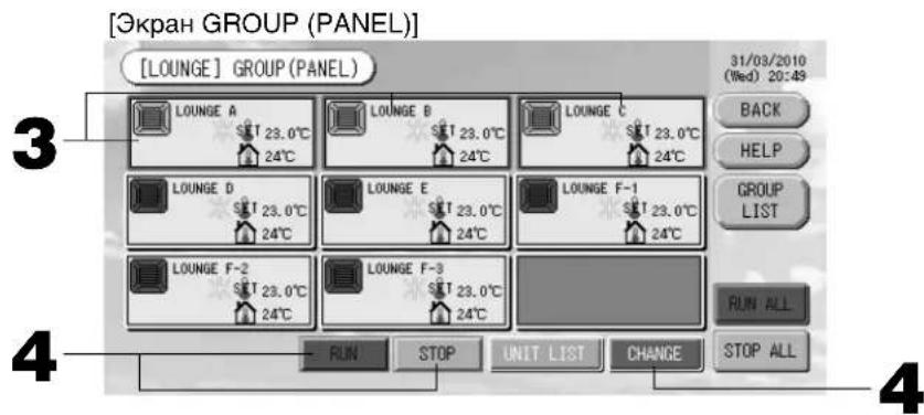
<Функионированue n octaHOB HeCKoJIbKnx rpynn>
- HaxMMte naHeIi Tex rpynn, IJIa KOToPbIX ONpeJeIOTcHAcTPOIKN (Moryr 6bITb Bbl6paHbI HeCKoNbKO rpynn).
Pamka naHeJI cTaHcTcHHeJ.
EcIn BbI xOHTe cDeNaTb OTMeHy, HaxMnTe naHEnb rpynnb eue pa3.
4.ДЯнЗAnycka yCToPOnCTB HxKMTe KHONKy RUN (3ANyCTNTb),a 3aTeM Ha 3KpaHe NOdTBePKeDeHnK Honky "Yes" (Ja).
BbipaaHra rpyna haueHT yHKUHOHPOBaTb.
IIOCTaHOBA yCTPOiCTB HaKMTe KONky STOP (CTO), a 3aTeM Ha 3KpaHe NOdTBePJKDeHnKONky "Yes" (Ja).
Bb6paHnra npnnna ppekpaaet yHKuHOHPOBaHne.
EcIn BbINONHtB HAcTPOkHy He HyxHo, HaxMnTe KhONKy "No" (HeT).
- Haxmte naHenn Tex rpynn, dna KOTopbIX onpeednIOCTc HAcTPOkN NIN BHOCATc N3MeHeHHa (Moryt 6bIb BbIbpaHb HeckoJIbKO rpynn).
Pamka naHeNn CTaHET CnHeN.
EcIn BbI xOITe cDeNaTb OTMeHy, HaxMnTe naHeNb rpynnbl eue pa3.
- HaxmTe KhONky CHANGE (N3MEHHTb).
OTo6pa3ntcA kpaH dIb BHeceHHN 3MeHEn Hpynn. Pn N3MeHEnN 3KpaHa HN OINH N3 npaMeTpOB ehe He Bb6paH (napaMeTp Tempeatpyb I Meet ncytoe 3haueHne). OnpeDenTe HAcTpoKn TOnbKO dIra TEX napaMeTpOB, KOtOpBle Heo6xOIMO yCTaHOBNb IIN N3MeHNb.

[HactpoKa HnDnBnDyalbHou 6NoKnpOBKn/ pa36NOKpOBKn Ha 3kpaHe HActpoKn fynKcn]
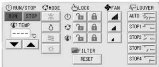
3TaФyHKU npIMeHUMa TOnbKO dNBAByTpEHHX yCtpoiCTB KXE4 nnn 6Oone HOBo MOdeJn nDnnybTa DnCTaHcNOHOrO ynpabNeHr RC-E1 nnn 6Oone HOBO MOdeJn.
5. Haxmte KhONky COOTBeTCTByUoIero npaMeTpA dJI erO HAcTpOuK NII N3MeHeHnA.
3anyck/ocTaHOB: HaxMnte KhoNky RUN (3AynCK) nn STOP (CTO).
C NOMOUI KHOKN RUN (3AIPYCK) MOXHO Haatb yHKUHNOHPOBAHne, a c NOMOUI KHOKN STOP (CTO) -ero OCTaHOBNTb.
- Hactpoika TemnepaTypbI: HaxMnte ▲ nll ▼.
YcTaHOBInTe TemnepaTpy Mekdy 18 n 30^
Pekim: Bb6epnte Auto (AbTomatueckn), Cool (OxnaJeHne), Dry (Cwka), Fan (BeHTnlaUHa) Ht Heat (OborpeB), Haxab COOTBeTCTByIOuOyIO KNONky.
-
ABTomatueckn pexm MOket 6bItb BKJIOueH B HAcTpOKe cyHKuN.
-
LOCK (БЛОКИPOВКА): Нахмпerte nлг
Ecnn Haxatb
,onepaunnybTaIncTaHcnoHHoro ynpaBneHnnaecn HaxkTa-3anpeaaOTca.
Ckopoocb BpaueHnBEHTnIaTopa: Bb6epnte a, a nHaXMnTe Ha COOTBETCTBYUOyIO KHONKy.
MOXHO BKJIOHTB B "Function Settings" ("IapaMeTpbl fYHKUIN").
- HanpaBJIeHne Bo3dyxa: BbI6epnTe Auto (aBTo), stop 1 (ocTaHOB 1), stop 2 (ocTaHOB 2), stop 3 (ocTaHOB 3)
nIIN stop 4 (OCTaHOB 4) nHaXMMTe KHONKy.
- FILTER (ФИльТP): ecnн HaЖаТа KHOпka CBрoca, 3HaЧOK ФильТра BыКЛIOуаTEСЯ.
BLOK pa6oTaet C MaKcImaJIbHoi cKOpocTbIO BEHTUNATopa.
6. Haxmnte KhoNky SET. Ha 3KpaHe NOtBepKdEHHaXmTe Ha KhONKy "Yes" (Ja).
Ecnn Hactpoiky nnn n3meHHe BbInonHrtb He HyxHo, HaxMnTe KhoNky "No" (Her).
PpIMeuaHne
-Пи Нжатин Ha Khonky BACK (HA3AД) BBinONHЯETcB O3BpAT K ppeblIyUeMy 3KpaHy.
- Ecnn Ha 3Kpahe "Function Setting" (HactpoKa cyHKcun) BKNIOyeHa cyHKcun 6NOKpOBKn/ pa3bNOknpOBKn OTDeIbHbIX ONepaCUN, NOBbIeTCB BO3MOXHOCTb pa3peWNTb ININ 3anpeTNTb ONepaCUN nyIbTa DnCTaHcNOHHORO ynpabNeHn IIN OTDeIbHbIX 3JEMeHTOB, a TaKxE INN KaXDoN OpeaCIN 3anycka/oCTaHOBA, yCTaHOBN peKIma n HAcTPOKn TEMpePaTypbl.
-Korda Ha 3Kpahe "Function Setting" (Hactpoika yHKcui) pa3pewehbl yHKcui 6IokpOBKn/ pa3bNOknpOBKn, onepaunnybta dNCTaHIOHOHRO ynpabneHn 3anpeuehbl, ecnn DnBCEX Oepaun 3anycka/oCTaHOBA, yctahOBKn peKmna n HACtpoikn TempepaTpybI yCTaHOBJeH 3haQOK . (HeKOTOpbie cyHKuIN, TaKe KaC c6poc 3HaUka fnhTppa, pa3pewehbl.)
KoMnJIeKcHbIe OnepaunC rpynnamn
B 3TOM pa3dene noka3aHo, KaK OnpedeJntb nn NImn3MeHnTb HacTpOKn KOMPJIeKCHO onepaun.
HacpoTe rpynnbl dna KOMnIeKChbIX opeaun 3anycka nnoocTaHOBA 3apaHee. CtpaHua 11 ① ,12 ⑤
- B rIaBHom MeHo HaxMnte KhONKy CHANGE ALL (N3MEHHTb BCE).

OTo6pa3ntc8 kpaH "CHANGE ALL" (U3MEHHTb BCE).
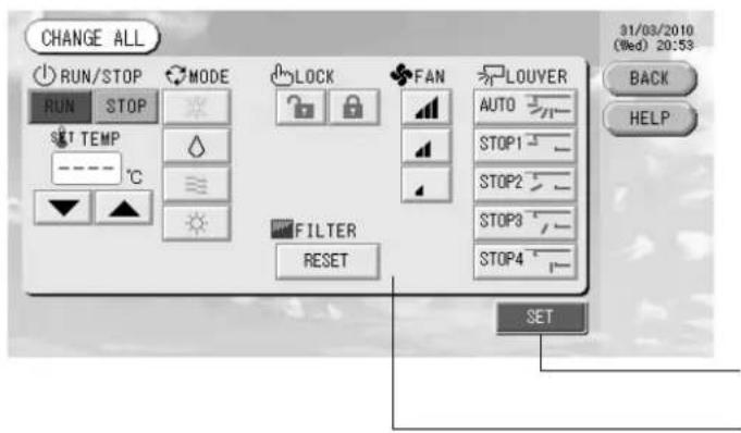
3 2
[HactpoKa HnDnBnDyanbHOn 6NoKnpOBKn/ pa36NOKpOBKn Ha 3kpaHe HactpoKn fynKcn]
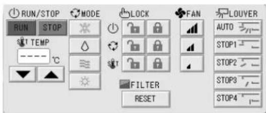
3TaФyHKU npIMeHUMa TOnbKO dNn BHyTpEHHX yCtpoiCTB KXE4 nIN 6OJee HOBOI MoJeN iDnA nyIbTa IInCTaHcIOHHO ynpabJIeHNr RC-E1 nIN 6OJee HOBOI MoJeN.
PpIMeuaHne
Ipi n3MeHeHH 3KpaHa Hn OdnH N3 npaMeTpOB eue He Bb6paH (napaMeTp TeMnpaTpyi IMeET nyCToe 3NaueHne). OnpeJeNTe HaCTpoiKn TOnbKO dIra Tex npaMeTpOB, KOtOpBie Heo6xOIMO yCTaHOBtB nNn I3MeHHTb.
2. HaxMMTe KONKcy COOTBeTCTByUoIero npaMeTpA dIra erO HAcTpoIK NII N3MeHeHnR.
3anyck/ocTaHOB: HaxMnte KhONky RUN (3ANYCK) nn STOP (CTOPI).
C NOMOJI KHOKN RUN (3A\PYCK) MOXHO HaaTa b YHKUHOHPOBAHne, a c NOMOJI KHOKN STOP (CTON) - ero ocTaHOBNTb.
- HactpoKa TempepatpybI: HaxmnteAnnV.
YctaHOBtTe TemnepaTypeMekdy 18 n 30^
Pekim: BbIeepntAuto (ABTomatueckn),Cool(OxnaJdeHne), Dry (Cyuka), Fan (BeHTnna) Hn Heat (O6orpeB), Haxab COOTBeTCTByoukyo KhoNky. - ABTomatnueckn peKm MOKeT 6bItb BKlOueH B HaCTpOKe cyHKuN.
- LOCK (БЛОКИРОВКА): НажмTe nii
Ecnn HaxkTa, onepaunn npbTa nncTahuOHoro ynpabneHna pa3pewauOTca, a eCnH HaxkTa -3anpeuaIOTca.
CkopoocbBpaueHnBAENTNJIaTOpa:BbIbePnte a, a, nJINnHaXMMTe Ha COOTBETCTBYOUYKHOHNKY.
MOXHO BKJIOHTB B "Function Settings" ("IapaMeTpbl fYHKUIN").
- HanpaBneHne BO3dyxa: Bb6epnTe Auto (aBTo), stop 1 (ocTaHOB 1), stop 2 (ocTaHOB 2), stop 3 (ocTaHOB 3)
ninn stop 4 (ocTaHOB 4) n HaxMnte KhONky.
Ecnn Hactponyu nn n3meHne BbInonHrtb He HyxHo, HaxMnte KhoNky "No" (HeT).
PpIMeuaHne
-Пинхатин Ha KhoNKy BACK (HA3AД) BbINOJIHHeTcB O3BpAT KпpeБыdUусму 3kpaHy.
- Ecnn Ha 3KpaHe "Function Setting" (HactpoKa cyHKcui) BkIIOyeHa cyHKcui 6IOKnpOBKn/ pa3bIOKpOBKn OTdeNbHbIX ONepaCm, NOBnRETCB BO3MOXHOCTb pa3peuNTb INN 3anpeTNTb OEPaCm INyTa INCTaHcNOHHoro ynpabNeHn dNt OTdeNbHbIX 3JeMeHTOB, a TaKxE INN KaJDoN OEPaCm 3anycka/OctaHOBA, yCTAHOBKn peKMa n HAcTPOKn TEMNEpaTypbI.
KordaHa 3kpahe "Function Setting" (HacptpoKa fynKun) pa3pewehbl fynKun 6IoknpoBKn/pa3bIoknpoBKn, onepaunnybTa nCTaHOnHO r ynpaBneHn 3anpeuHb, ecnn IyBaBex Oepaun 3anyCka/OctaHOBA, yctaHOBN pexIma HAcTPOKn TEMNepaTpybl yctAHOBnEH 3haOK . (HeKOToPbE fynKUn, TaKe KaK c6poc 3HaUcKa fInlbTpA, pa3peweHbl.)
Hac troponka pacnncanra
PacncaHna yHKIOHOPOBaHna MOKHO yCTaHOBtB dIy yCTPOINCTB B rpynnax. IIN BpemeHn cyHKIOHOPOBaHna (BMHyTAX), Oepaun 3anycka/oCTaHOBA, pexNMa cyHKIOHOPOBaHna, 3anpeueHn BblONHeHn Oepaun C npbTa DnCTaHIOHHOro UnpabLeHn HAcTPOKn TEMpepaTypbI MOXHO 3apeInCTpnpoBaTb DO weCTHaDcauTn pacncaHn B Deh. CoCTaBBte 3apahee noDpo6Hoe pacnccaHne Ha denb (Denb HeJeN, Ppa3dNk, oocbI denb 1, ocobI denb 2). CTpaHnca 21
1. B rnaBHOM MeHIO haxMnte KhoNky SCHEDULE SETTING (HACTPOUKA PACINCAHNA).
CTpaHnca7
Отобразсгд Зкран "SCHEDULE SETTING" (HACTPOИKA PACINCAHИ).
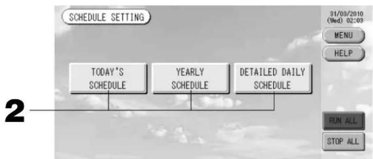
Hactpoika pacnncahna Ha Tekyuyn DeHb
PacncaHne yHKUHOHPOBaHn dIy TeKyuero DnH COCTaBnaTcN da KaKdo rpynnbl.
- Ha 3Kpahe "SCHEDULE SETTING" (HACTPOIKA PACINCAHNA) HaxMnte KhoNky TODAY'S SCHEDULE (PACINCAHNE HA CEROHN).
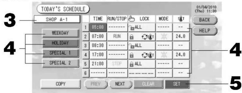
3. Haxmte mma rpynnbl.
Ha 3kpahe "Select Group" (Bb6op rpynnbl) Bb6epnte rpynny. CtpaHua 22
4. B cπncke hαxMnte ha n3MeHЯEmbI npaMeTp.
Ecnn Haxk TaB KOnKn "Time" (Bpem), "Lock" (BloKnpOBka) nnn "Temperature setting" (HacTpoKaTeMnePaTybl), dna KaKdoRo 3JeMeHTa OTo6paKaetc3KpaH c noDpo6Ho INΦopMauné O hAcTpoKax.
CTpaHnUbi 22,23
I3MeHnTe HacTpoKn npaMeTpOB “RUN/STOP” (3AUYCK/OCTAHOB) nIn “MODE” (PEXKM), NaKaB COOTBETCTBYUOUI 3JIeMEHT.
Inepexoanda cTpaHnUbHa cTpaHnUy HaxMnte KhONky PREV (PPE.D.) nnN NEXT (CNE.D.).
4. BbI6epnTe KhoNky WEEKDAY (DEHb HEDEJN), HOLIDAY (INPA3dHNK), SPECIAL 1 (OCOBbIM DEHb 1) nII N SPECIAL 2 (OCOBbl IN DEHb 2) nHaXmnte ee.
PpMueHne
BbIOpHnTe 3apaHee noDpo6Hyu HactpOky paCnncaHH yHKUHOHPOBaHH Ha DeHb.
Uka3aHO HnXe (HacpoKa noDpo6HOro pacmcaHn Ha DeHb)
5. HaxMMTe KONky SET. Ha 3Kpahe NOpTBePckDeHnHaXMMTe Ha KNONky "Yes" (Da).
Ha 3kpane "Select Group" (Bb6op rpynnbl) Bb6epnte rpynnny. CtpaHua 22
4. Bb6epnto np06hoe paoncaHne Ha deHb, Haxab KhoNky WEEKDAY (DEHb HEJIN), HOLIDAY (PNA3HNK), SPECIAL 1 (OCOBbl DEHb 1), SPECIAL 2 (OCOBbl DEHb 2) uN NO OPERATION (No OEPALUN).
PpIMeUaHne
BbIOpHnHTe 3apaHee HacTpoKy noDpo6HOro pacnncAHn Ha DeHb.
Yka3aHo HnKe (HacTpoKa noDpo6HOro pacncaHn Ha DeHb)
5. Haxmte daTy (MOXHO Bbl6paT HeckoJbKO daT).
Iopoboe paCncaHne Ha deHb, KOtOpoe 6ydt Bb6paHo, OTHocntcK 3TOMy dIO. OHaKO TekyuN DeHb npoWeJnne DaTbHeOCTynHb IaBb6opa. IaN n3MeHeHn MeCAua HaxmTe KhONky PREV (PPE.D.) nn NEXT (CJIeD.).
PpIMeuaHne
Пи Нжати Na Khoнky DEFAULT (ПО YMOЛЧАHИО) cy66ota n BOCKpeceHbe yCTaHaBJIbIbaIOTc KaК паЗднIKn (holiday), a ocTaJIbHbIe dHI KaK dHI HeJeN (weekday).
6. HaxMMTe KONky SET. Ha 3KpaHe NOtBepXeHnHa XMMTe Ha KHonky "Yes" (Ja).
Ecnn Bbl He xotnte coxpaHrTb 3Tu npaMeTpbl, HaxMnTe KhONky "No" (HeT).
- Пин Нжати Na Khoнky BACK (HA3AД) BBINOJIHЯETcB BO3BpaT K эКраHy “SCHEDULE SETTING" (HACTPOIKA PACПИСАИ).
-Прии Нахкати Na Kногу COPY (KОПИРОВАБы) otКроетс 3Кран "Copy Schedule Screen" (Зкран КОпіровану paСпсан) Дд КОпіровану napametpoB мexДу рупnam. -Страница 23
HactpoKa nOdpObHoro pacncaHnHa DeHb.
Poiop6hoe pacnncahne Ha deHb coCTaBnaTc nla KaKdoI rpynnbl.
Pacnncahne coctabnetaonpeJeHHeHO nHa (Heh HeeIn, npa3HNuHbI DeHb, ocobn 1 n oocbien 2), npexim cyHKUHOHPOBaHnB 3TN dH MoKet 6bItb HAcTpoEHn KaKdoN 3 rpynn.
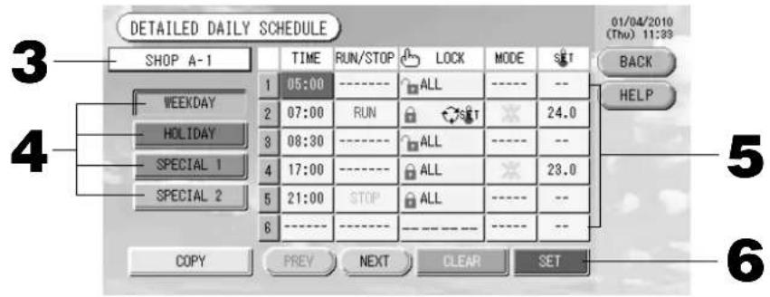
-
Ha ekpahe SCHEDULE SETTING (HACTPOIKA PACINCAHNA) HaxMnte KhoNky DETAILED DAILY SCHEDULE (IOIDPOBHOE PACINCAHNE HA DEHb).
-
Haxmte mra rpynnbl.
Ha 3kpane "Group Select" (Bb6op rpynnbl) Bb6epnte rpynnny. Yka3aHO Hnke (Pa3nHbIe 3kpaHbI)
- Bb6epTe noDpo6Hoe pacncaHne Ha denb, Haxab KhoNky WEEKDAY (DEHb HEJEIN), HOLIDAY (IPA3HNK), SPECIAL 1 (OCO6bI IN DEHb 1) nnSPECIAL 2 (OCO6bI IN DEHb 2).
- B cnncke haxmnte Ha n3MeHHeMbIn npaMeTp.
EcnnaKaTb KhoNKn "Time" (Bpem), "Lock" (BloKupOBka) nnn "Temperature setting" (HactpoKa Tempeatpybl), dna KaJIOrO 3nemeHTa oTo6paXaETcra 3kpan c noIrpOboHnHOpMaunen O hAcTpOaNkax.
CTpaHnUb1 22,23
I3meHnte HacrpoKn npametpoB“Run/Stop”(3anyck/OctanOB) nnn“MODE” (PEKIM), haxab COOTBETCTByoUeN 3JEMENT.
Ipn Haxatn Ha KhoNky CLEAR (OCHCTNTb) Bce Bbl6paHbIe npaMeTpbi OOnuAHTcA.
PpIMeuaHne
-При Нжатин Н Кногу BACK (HA3AД) Вьлелгетсь Bo3BpaT K эКрану "SCHEDULE SETTING" (HACTPOИKA PACПИСАНЯ).
- Haxmnte KhoNky COPY (KONIPOBATb) npn konnpoBaHn pacnncaHm MeJy rpynnam.
CTpaHua 23
Pa3nHbIe 3KpaHbI
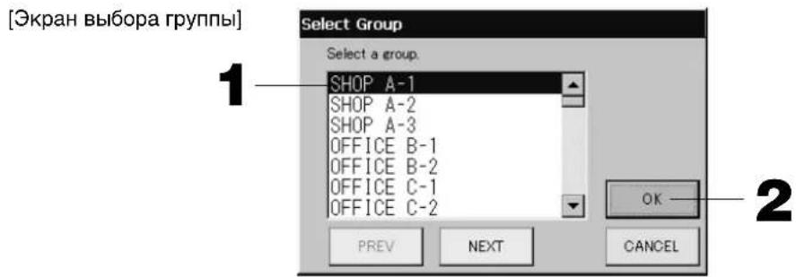
- Haxmte mBbI6paHHo rpynnbl.
MBA BbipahHOIpynnBbICBeHnBaETCn INHbpchom pexnme.
Для nepexoja co ctpaHnCbHa ctpaHnCy haxmTe KhoNky PREV (PPEД.) nii NEXT (CJIeI.D.).
- HaxmTe KhONky OK.
Ipn Haxatnn Ha KhoNky CLEAR (OCHCTNTb) TeKyuee 3NaueHne ydaJIReTc, n npaMeTp cTaHOBnTcnyctbIM.
[3KpaH pacncaHn KOnIpObaHn]
Bb6epTe rpynnbl, K KOToPbIM npImeHmO Bb6paHHoe paNCaHne.
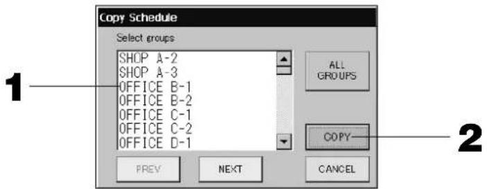
- Haxmte mMa BbipahHo rpynnbl (MOxHO BbipaTb HeckoIbKO rpynn).
- Ha 3kpaHe SYSTEM CONFIGURATION (HACTPOIKA CNTCTEMbl) HaxMnte KhoNky ACCOUNTING PERIOD (NEPNOy UYETA). CTpaHnua 8
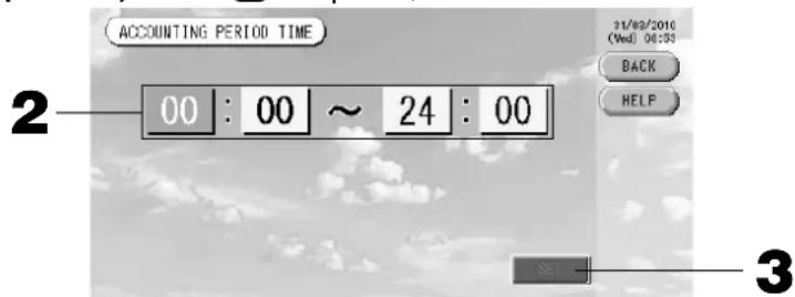
2.ДЯ yctaHOBKn BpeMeH NaHaJana Nn OKOHuaHn HaXMMte Ha KHONK Yaca Nn MmHyTbI.
BVeIe Ie BpeMa. CtpaHua 26
- HaxmTe KhoNky SET. Ha 3KpaHe nOtBepXeHnHaXmTe Ha KhoNky "Yes" (a).
Ecnn BbInonHrTb HacToPouKy He HyxHo, HaxMnTe KhoNky "No" (HeT).
Пи Нжати Н Кногу BACK (HA3AД) BBINOJIHЯETcB 03ВрТ K ЭкраHy "SYSTEM CONFIGURATION" (Hacrtpoиka cnCTeMbI).
BHHMaHHe
Pacchet 3Hepro3aPat dJaDaHHoro npnbopa He COOTBcTByeT HopMaM MeJyHapOnHO opraHn3aun 3aKoHoDaTeJIbHOm MetpOlonn (OIML), nO3TOMy npaBnIbHOcTb pe3yIbTaTOB COOTBcTByOuX paCteTOB He rapaHTnpuyETca.
DAnHbI np6op paccuHTbBAeT Tolbko pacnpeJeHne 3Hepro3aTpat (ra3a, 3JeKtpo3Heprnn).
Bam Heo6xOIMO paCCHTaB KO30pHnueHTb KOHdNtHOHPOBaHr BO3dyxa.
CoxpaHIOCTpacHTbIe daHHbIe Ira HactoIero N DByx npdeBdyuix MeCAUEB.
Cm. Ctp 28 (nCnoJb3ObaHne naMaTn USB) o MeToDnke coXpaHeHH paCteTHbIX daHHbIX.
Поле3нble Функции
BbOaIqdpN cIMBOJIOB
BBoD uΦp
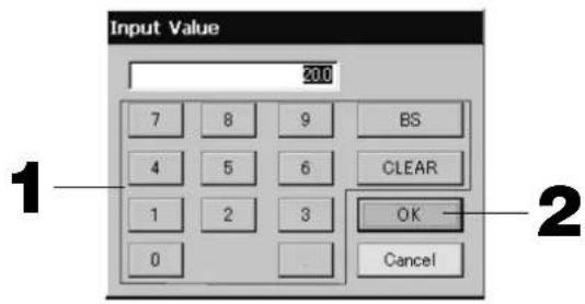
- Haxmte KhONKn dnn BBOda COOTBETCTBYIOe OncnHnHO 3haueHnA.
KhoKa“BS”:BO3BpaHaIar(ydaJIeHneOHOHcPbbl).
Khonka CLEAR (OCHCTITb) : ydaene Hne BBeHbIX CmBOLOB (ydaeneHne Bcex cnpp).
- Haxmte Khonky OK.
Lcnppa 6ydeT n3MeHeHa n 3KpaH 3aKpoetc. IInr OTMehbI n3MeHeHn HaxMnte KhoNky CANCE (OTMEHA).
BBOD CnMBOJIOB
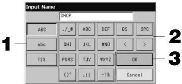
- BbI6epnte 6yKBy u HaXMMTe KHONky.
- BBeDnTe mMa rpynnbl.
Korda Bb6paHa KhoJa "ABC" nIi "abc", KaJdoN KHOJaTcH HeCKoJIbKO 6yKB, npN KaJdOM HkaTn KNOHKn CmBOJ MeHReTcR.
Khonka“ABC”:BBOID npONCHbIX 6yKB.
Khonka"abc":BBOIDCTPOUHbIX6yKB.
KhoKa“123”:BBOUuΦp.
Khonka "BS": BO3Bpat Ha 1ar (ydaJIeHne OJHOrO CmBOJa).
* IMeHa 6nOKOB nnn rpynn MOryT coOpKaTb Do 16 CmBOnIOB.
HactpoKaФyHKcN
Iopda3yMeBaetc, yTo cyHKm TaM-ayTa BblKJIOUeHn noDCBeTKn, BKIOUeHn/BBkJIIOUeHn KHOKN aBTOMaTneckoro peKIMu 6bOKnpoBaHn/pa36NoKpOBAHn OTJeBhIX cyHKm nYnbTa dNCTaHOnHHOrO ynpabHeHn yCTaHOBHebl. PInuImeHn HAcTpOeK cyHKm cNeDyTe npBedeHHbIM HHXe IHCTpyKmR.
- B rIaBHOM MeHIO HaxMnte KhoNky FUNCTION SETTING (HACTPOIKA ΦYHKLI).

CtpaHnua 7
[3KpaHnactpoKn cyHkui]
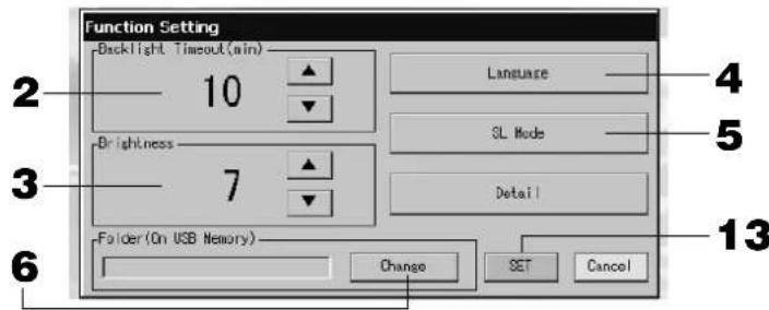
[3KpaH“Detail Setting”("PapameTpbl detae")]
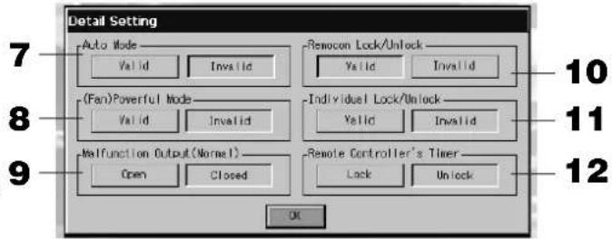
- C nOMOsbIO KHOIOK ▲▼ BbIePHTe BpeM dIaM-ayTaN TaM-ayTa NOcBETKn. (3aBOcka yCTaHOBka no yMOJuaHNO : 10) C nOMOsbIO 3ToI onepaun MoxHo BbIpaTb BpeM BblKJIIOUeHINr noDCBETKn ceHCOPHoro 3KpaHa IocJIe BBINOJIHeHn r NocJeDHeOnepaun.
- C nOMOsbKHO KHOK ▲BbI6epNTe rpkocTB.(3aBOcka yCTaHOBKa NO yMOJIaHIO : 7) MoXHO BbI6paTb RpKOCTb NODCBETKN MOHITopa.
- N3MeHnTB "Language" ("A3bIK"). Прн HaxaTm 3ToK HONK MoXHO Bbl6paTb HyXhBIM A3bIK. O6paTNTecb MaRa3HH, B KOTOpOM 6bl npno6peTeH 6JOK.
5.Измeнть“SL-Mode”("Pexm SL").IcnoJb3yIte daHHyO yHKuIO dIЯ HacTpOuKn CnCTembl CBa3N (3aBODckaYcTaHOBKa:New(Hobli)).ObbIHy eE He HaDo I3MeHATb.
HeBepHbI npaMeTpbl HAcTpoKm Mory T npnbEcTn K NoTepe CBa3n C qactbIO uIN Co BCEM NOKJIIOeHHbIMN KOHNIOHOpeAMn.
Poxkanytcta, 6paTntecb B Mara3NH, B KOTOpOM Bbl Kynnn OobpydoBaHne.
- HaxmTe KhONky Change (N3MeHnTb).
Bbl moke Te yka3aTb nanky dnnnepeHocapaccuHTaHHbIX daHHbIX B naMaTb USB. (ToIbko dnn SC-SL3NA-BE).
- Haxmte Khonky "Valid" (BkIoueH) nIu "Invalid" (BbIKIOueH) IJI pexma "Auto" (ABTomatueckn). (3aOcKa yCTaHOBka no yMOUaHIO : Invalid (BbIKIOueH))
3To DeiCTBne DeJaet DoctynHoi Hn HeDocTynHoi KhoNky AUTO Ha 3KpaHe GROUP SETTINGS (HACTPOIKI IpyPiIb) n 3KpaHe CHANGE AII (U3MEHHTb BCE).
EcnI dIa aBToMaTHueCKOro peKIma yCTaHOBHeO INVALID (BbIKJIoueH), KONka AUTO He nOBnAETcHa 3kpaHe.
Dahna yHKun MOKet 6bIt npimeHeHa K BHeuHm ycTpoNCTBaM, KOtOpBie OTHoCrtCa K oxJaDaOuHm/HarpeBaOuHm ycTpoNCTBaM cepn He3aBNCmbx MyJbTN-KXR, GHP-R nJn 60nee no3dnHex PAC.
PoxkanyuCTa, He nCnoNb3ynte ABToMaTuYeCKn pexKIM dIa BHeUHnx yctpOcTb, He yNOMaHyTbIX Bblwe.
PoxkanyuCTa, 6paTntecb Mma3nH, rde 6blno KynJIeHO yCTpoIcTBO.
- Haxmte KhoNky "Valid" ("DeiCTBnteIbHo") uIN "Invalid" ("HeJeCTBnteIbHo") dJIa "Fan Powerful Mode" ("YcHneHHoro pexnma pa6oTbI BeHTnIaTopa"). (3aBOIDcKa r cTaHApTHa HacTpoJa: "Invalid" ("HeJeCTBnteIbHo"))
Pn 3OM BKNIOaETcH Nn OTKIOaETcK HONKa Ha 3KpaHe "GROUP SETTINGS" ("IAPAMETPbI PPyINbl") n 3KpaHe "CHAGE All" ("N3MEHHTb BCE").
EcnI pexima "Fan Powerful" ("YcunHeHHa pa60Ta BeHTnIaTopa") 3aHa napameTp "Invalid" ("HeDenCTBnteHbHO"), KONKa OTo6paXaETcHa 3KpaHe.
O6paTntecb B MaRa3nH, B KOTOpOM 6bln npno6peTeH 6Iok.
- Дли napametpa "Malfunction Output (Normal)" (Выбов сигнада оь ошибke [obiyhny]) Вьберпe "Closed" (3akpbiT) ил "Open" (OTkpblT). (3abodckay yctaHOBka no ymonuahnio : Closed (3akpbI))
Дляфункци Вьдачи снгналаобошнбк Bo Врм оьчHoro peхима pa6otbl yctpoiCTBa KOHdunohnpobAHn BO3dyxa MoKHO BbIbpaTb coToHne "Closed" (3akpbIT) nnn "Open" (OTkpbl).
IINyueHn IOnoHNteBHO HOpMaun OpaTntecb K npctaHTeIO cepBnCHO cnxkbI INN CneuaNCTy, KOToBb BInONHJ YCTAHOBKY CNTEmbl.
- He3aBnCmO OT napametpa 3anpeTa ydaIeHHoro KOHTpOJInepe, ecn npuynpaBHeHn ODNHM KOHNIOHEPOM C NOMOsbHO HeCKoNbKHX cHTpaNbHbIX KOHConeyka3bBaIOTcpa3NNHbIE napametpbI dAHHORO KOHNIOHEPA, MoKeT cnyITbcra TaK, YTO daHHBI KOHNIOHep He BKNIOHTcC nYbTa DY. No3tomy B daHHom cnyae cneJyET yCTaHaBnBaTb napametp pa3peWeHH/3anpeTa ToIbKO Ha rnaBHOn CEHTpaNbHbOH KOHCOII, a He Ha ynpaBJIreMbx ceHTpaNbHbIX KOHCONX.
(3abodckayyctaHOBka:ValidPa3peweho))
Ho B cnuyae, ecn K daHOMy ueHTpaIbHOMy nyIbTy ynpaBneHn NOkNIOueHO BHeWHee ycTpoIcTO, KaK HApIMep, YcTPOIcTB aBapuHOrO OCTaHOBa, To daHna HaCTPOJka DOxKHa 6bITb OTMeueHa KaK "valid" (pa3peSeHo).
Ioxaanynta, 6paTntecb B Mara3H, B KOTOpOM Bbl KyuNlN o6OpydoBaHne
- Haxmte Khonky "Valid" (BkIoueH) nIy "Invalid" (BbIKIOueH) dIy peXnMa "Lock/Unlock" (BloKOpBa/pa36NoKOpBa). (3aBoDcKa yCTaHOBka no yMOJuaHIO : Invalid (BbIKIOueH))
Pn 3OM BKNHouaETcN IIN OTKJIOUaETcN cyHKuIpa3peWeHn N 3anpeeHn OTdehHOOnepaun, BBINOJIHReMoC NOMObIO NyIbTa INCTaHcNOHOro ynpabHeHn, TaKo KaK 3anyck/OctaHOB INI ONpeJeHne HAcTPOeK peKmMa n TeMnepaTypbl.
PnmuMeaHne
3TaФyHKUINI npIMeHmMa TOnbKO IJI BHyTpEHnX yCtpoiCTB KXE4 nII 6OJee HOBOI MoEJI IN IJIpyIbTa DnCTaHcUNOHOrO ynpabJeHnR RC-E1 nII 6OJee HOBOI MoEJI.
- Haxmnte KhoNky "Unlock" (Pa36noknpoBaTb) nIn "Lock" (BLOKpOBA Tb) nIra TaImepa NylTa dntaHcOnOHoro ynpabLeHHr. (3aBOckaYCTaHOBka no yMOJuaHHIO : Unlock (Pa36nokpOBA Tb))
3To DeiCtBnpe pa3pe7aet nIIN 3anpe7aet onepauTO TaMepa NylTa DnCTaHIOHOrO ynpabNeHnA Bcex KOHNIOHepOB BO3dyxa, ONpeJeNHHbX B rpynnne.
- HaxmTe KhoNky SET.
Длг OTMeHbI n3MeHEn haxmnte KhoNky CANCEL (OTMEHA).
PpIMeuaHne
YCTAHOBITE KAK MOXHO 60Jee KOPOTKIN nepnoI dIa TM-ayTa NOcBETK, YTO6bl IPOJNTb cPOK cnjkbI XnDKOKpncTaNIIueckCkOro 3KpaHa.
YcTpaHHeHnE HApUWeHnE 3JleKTpOnNTaHnE
B cnyuae npekpaennoaun 3Heprn daHHbie coxpanHOTCA
- KOnchpyaunCnCTeMbI onpeJeHa Ha cTpaHnue 8
- NapametpbI rpaHka yKa3aHbHa cTpaHnue 20
- IapameTpbydyHKunyKa3aHbHa CTpaHnue 27
-Даннные pacуета зернотpeблени до пекаши подаи зерни (Toько SC-SL3NA-BE)
Bcnyae npekpaueHnnoDaun 3Heprn daHHbIe He coxpaHrTOCA
- YcnoBna pa6oTbI n npedyctaHOBHeHoe cocToHne KaKdoR BHyTpHHeRo 6noka nepei npekpaueHem Noaun 3heprnn (BKIOUaer peXm pa6oTbI, yCTaHOBHeHHyIO TeMnepaTyPy i npedyctaHOBHeHHoe COCTOHNpe pa3pehenn nn 3anpeTa Ha ynpabHeHne c NOMOsbIO nyIbTa Dv n. d.).
B TOM cnyuae, ecnn nonHoe obecToUBaHne cnCTeMbI npoJnTc6Oone 48 yacOB, BHyTpEHHe Yacbl octaHOBTcN HAcTPOkN paCncaHn JIA KaKDo rpyNbI 6yDyT NotepRbI. IpeyeCTaHOBtE Bpem Ha Yacax. Het Heo6xoDMocTn nepeyctaHaBnBaTb Yacbl, ecnn noDaay 3NeKTPoNTaHn 6bJa OTKIOueHa MeHee Yem Ha 48 YacOB; KaKdA rpyPnA 6yDcT paBoTaB/OCTaHOBtCBc corNaCHO CneDyIOUIM npabNJam.
Pn BO306HOBHeH No Daun 3eKTPoNTAHn KaJdA rpynna 6ydt FyHKUHOHPoBaT B COOTBETCTBn C HAnboJe 6IIN3KmM NO BpeMeH NaCTpoiKaMn pacncacHn. Ecn dHa HAnboJe noDxoJaero paCncaHn HaCTpoKn He OnpdeJeHb, 6ydt NcNoJIb3OBAtcbr BTOPOe HAnboJe nOdxOJaee pacncaHne.
EcnI nTKeKyUero DNH He T HAcTpoEHHO paCncaHn, DaHHbI ueHTpaBbHbI npbT ynpaBHeHn He 6yDet nepeDaBaT HnKaKne CnHaNbl Hn OdHou n3 rpynn.
IcnoJb30BaHne naMaTn USB
BHHMaHne
- Y6eIntecb,чTo nCnoB3yETc npinlaraemaan naMaTb USB.
-Ob3aTeIbHO BbINOHNHe 3Tn DeINCTBnA NOcNe yCTaHOBKn B ycTPOiCTBO nAMrTu USB. TpaHnca 4 - CoxpaHIOITc paCHTbIe DaHHbIe IIN DBeHaIaTn MeCAUeB. IoxaanyIcTa, coxpaHInTe Hx Ha PIK npnOMOuN nAMrTn USB B TeueHne DBeHaIaTn MeCAUeB.
- IoxaIyIcTa, He pa6oTaIe C o6OpyIOBaHHeM, ecIINHdNkaTOp USB yCTpoCTBa 6bICTPO Miraet.
Ecnn HndkaTOp USB yctpoeCTBa Mnae T MeDneHNO, TO C yctpoeCTBOM MOXHO pa6oTaTb nnOTKIOUHTb erO.
Ecnn ycTpoCtBO USB, KOTOpoe Bbl npImeHReTe, He NMeet KpacHoro INnKaTopa, To nocne BbINnHeHr OTeJbHOI ONepaun Hno6XoDmO HEMHOro NOdoxJaTb.
YcTpoNCTBO USB nAMHTn MOKHO CHaTB, KOrDa Bbl BbINOHmN uCOxpaHmN BCE OepaLIM.
Byet yio6hee,ecnB namrtn USB 3apahee co3aTb npKn.
- B rIaBHom MeHIO haxMnTe KhoNky IMPORT EXPORT (IMNOPT/3KcNOPT).

CtpaHnla7

2. HaxmTe KhoNky "Export monthly data files to USB".
Ha 3kpahe "Folder Selection" (Bb6op nanKn) Bb6epnte nanKy.
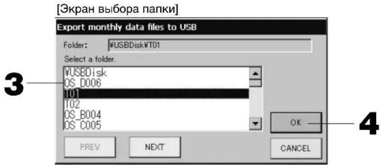
3. Haxmte mR Bb6paHHo rpynnbl.
Для nepexoja co CTpaHnUbHa CTpaHnUy HauKMnte KhoNkY PREV (PPEД.) uH NEXT (CJIEN.D.).
4. HaxmTe KhoNky OK.
OTo6pa3ntcA kpaH noTBePxxDeHn (OkHO noTBePxxDeHn 3KcnpTnpoBaHn paIa BbIHCneHHbx DaHHbIX/3kpaH noTBePxxDeHn pe3epHoro KOnnpoBaHn paIa onpeJeHn). Ha KaKOM-JIn6o n3 3KpaHOB HaxMnte "OK".
PpimueaHne
- Iocne Haxkataa KhoNk CANCEL BbInonHareTc Bo3BpaK npdebyuemy 3KpaHy.
- IcnoIb3OBAHne KhoNKn "Import a configuration file from USB" (Mnopt paJa KaHpIpyaun c USB) He Tpe6yeTcra.
- INHOpMaIHO O BbIIOJIHeHn paCteTOB Ha KOMIbIOTepe CM. Ha npuJraEMOM KOMNaKT-DnCKe.
BaXHO!!
Pacuet daHHbIX.
(1) BbINOHNHe cneIyOuIyIO npoueDpy IJIa nepeDaun BbIcNHeHHbIX DaHHbIX Ha yCTpOcTBo USB nAMrTn.
(2) CHIMITE yctpoictBO USB namrnc zentpaalbHoro nyIbTa ynpabNeHnna NOcOeINHTe erO K KomnbIoTepy.
(3) BCTaBbTe npnlaeMbI KOMNaKT-DnCK B KOMNbIoTe p 3anyctnte nporpaMMHoe o6ecneueHHe.
(4) IcnojIb3yIte nporpaMMHoe obecneueHne B COOTBETCTBn C MeHIO KOMNaKT-DnCKa.
* Het Heo6xOIMOCTN NOCTORHHNO DEpXaTB NAMrTB USB NODCOEINHEHHO K yCTPOIcTBy.
*Iocne ycTaHOBKn BbUncnnteBhoro nporpaMMHoro oecneueHna, Heo6xoDmO BblonHtB 3) n (4). Pa6otaTe TOnbko C Tem nporpaMMbIM oecneueHnem, KOtopoe ynOMHaetcB pyKoBOdCTBe Ha KOMNaKT-DnCKe.
- B rJnaBHOM MeHIO HaxMnte KhONky IMPORT EXPORT (MMNOPT/3KcNOPT). CtpaHnca 7
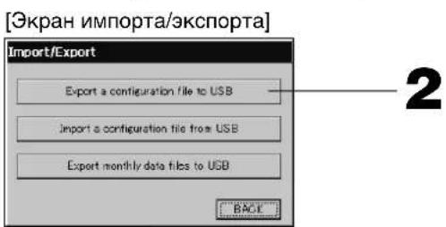
2. Haxmte KhoNky "Export a configuration file to USB" (3Kcnpot faoJa konHpyaun B naMrtb USB).
Ha 3kpahe "Folder Selection" (Bb6op nanKn) Bb6epnte nanKy. Btre [KpaH Bb6opa nanKn]
PpIMeuaHne
- Пи Нжатин Н конь BACK (HA3AД) Вылоннетсь BO3Врт К ппдушему ekpaHy.
- IcnoIb3OBAHne KhoNKn "Import a configuration file from USB" (MmnpT paJa KaHpIpyaun c USB) He Tpe6yeTcra.
Pn pe3epBHom KOINPOBaHm KOHpyaIOHHbIX DaHHbIX MOXHO JERKO CKONIPoBaTb CNeDyUOyIO IHOpMaIIO:
onpeedeeneHn 6IOKOB Ipynn
- HacTpoIKN paCnIcaHNI
Ppocmotp cncka npednypeinteIbHbIX CNrHaIOB
- Haxmte daTy, KOTopyu Hyxho ydaNtB.
Bb6paHnA daTa 6yTe BbcBceHeHa. DaTy MOXHO n3MeHnTb C NOMOuK KOHONK
- Haxmte Khonky DELETE.
Bb6paHnHa 3aHc b6ydt ydaheHa n3 cncKa npdeynpeDnteBhix CnHaIOB.
- Haxmnte KhONky DELETE ALL.
I3 cnncKa npedynpeinteBbIX CnHaNoB 6yUyT ydaJeHb BCE 3aNNc.
- Пин Нжатин Н Кнонку BACK (HA3AД) Вьлпоггетсь BOЗрат к Зкрани "SYSTEM CONFIGURATION"
(HactpoJa cncTeMbI). CtpaHnua 8
HΦopMaunO cnCTeme
3deb moxho y3HaTb BepcnIO CnCTembl ynpabJIeHnKoHdIuHOhepOM (Air-Conditioner Management System).
B cnyae SC-SL3N-BE, Bbl MOKeTe NOITBepNTb IHeBHOI BMnIyNbCHbIX CnHAnOB OT CHTNka ra3a nn BOdb. Bbl MoKeTe y3HaTb NODcHTaHHYIO 3NeKTPuYeCKIM CHTNKOM IIN Ra3OBBIM CHTNKOM BeJIuHHy NOTpe6IeHnI 3Heprnn 3a TeKyun DeH.
- B rIaBHom MeHIO hXmnte KhoNky SYSTEM INFORMATION (HhOPMALnO CnCTEME).
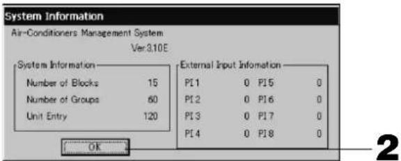
- NocJIe npocMoTpa copeKHMoro 3KpaHa haxMnte KhoNky OK.
3KpaH CnHΦopMaunne O cncTeMe 3aKpoeTc.
Cnpabka
- HaxmTe KhoNky HELP.
OTo6pa3ntcA cnpaBOuHb 3KpaH dIa Tekyeero 3KpaHa.
PpOcMoTpnte ero coDepeKHMoe c nOMoubIO KHOHOK ▲
- HaxmTe KhONky BACK (HA3AД).
Pn3TOM 6yDenBbINOnHeN B03BpaT K npeBbIyUeMy 3KpaHy.
Овслужимbaне
ДячNTKУ YCTPOINCTBA HcnoJIb3yIte MArKyIO cyXyIO TkaHb. EcIn yCTpoINCTBO CnIbHO 3aRpa3HeHO, pactBOpITe B TeNIO BOJe HeINTpAlbHOE MOIOUe CpeIDCTBO, CMoHTe B HEM caIΦETky I npOTpIte yCTPOINCTBO (KpOME CEHCOPHOI NaHEn). Pocne 3TOrO cMOHTe caIΦETky B YnCTOIN BOJe I npOTpIte yCTPOINCTBO eIe pa3.
BHHMaHne
He nCnoJb3yIte pactBOpnteJIb IaKpaCKn, opraHnueckn pactBopnteJIb IaN KOHcHTpnpOBaHHyIO KNCJOTY.
Pn3OM MoKet N3MeHHTbCA UBeT yCTpOJCTBa, a TaKKe MOKET 6bITb CHrTa eRo OKpacka.
BbIKJIIOUHTb
Ipn HaxkTm KhoNk SHUT DOWN (BbIKIOHTb) B IaBHom MeHIO, OTo6pa3nTcA KpaH noDTBePxDeHnI Heo6xoDIMO 6yTe BBecTN CBOI napOJI.
(*) O6paTnTecb K cTp. 6.

Pn HaxkTm KhoKn Yes (Ja), npOn3oJTeNpeKeHoueHne Ha yKa3aHHb Hxke 3KpaH (a).
Poxkanynta, nooKdnte, noka He noBtca coocheHne "Please switch off the power supply." ("Poxkanycta, BbIKJIOHTe NCTOCHNK NITAHNA.")
EcnBbI He BbIKIOuINI INTaHne, HaxMnte KhoNky No (HeT).
Korda npo3oien TnepeKnioueHnne Ha yka3aHHb HnXe 3kpan (b), Bbl MoXeTe BbIKIOuHTb NtAHe.

(a)


(b)
YcTpaHHeNHe HenCpabHocTei
| Отоображется кел'tь Значок усточва. | В раobote усточва поэдем сбов. Немпавное усточвoc octааналmaьетс. Оватиесь по месучппимрор,在посточва. Пиообшениnotpebetyetc cneуюшад Инфомразимя:"цовETзнЧаССССССССССССССССССССССССССССССССССССССССССССССССССССССССССССССССССССССССССССССССССССССССССССССССССССCS" "СHTУАДМ,пспКOTОП proINCXOXHNTC60B Раobote", "МоДь HeINCPABNO pabotAOUIOE YCTPOCTBa", "HOMER OUIKOK (E00)" n.T.D. | |
| Отоображется сини зачok усточва. | Вознлka kommyнakuaioHHa noPbIeMa. Оватиесь по месучппимрор,在посточва. Пиоobшениnotpebetyetc cneuouшад Инфомразимя:"цовETзнЧаСССССССССССССССССССССССССССССССССССССССССССССССССССССССССССССССССССССССССССССССССCS" "СHTUAZM,пспКOTОП proINCXOXHNTC60B Раobote", "МоДь HeINCPABNO pabotAOUIOE YCTPOCTBa", "HOMER OUIKOK (E00)" n.T.D. | |
| Горот 3нak Фильта.Очирстite | БOSTДИНДФИТ. (CnOOSO CHSTK CM. B yRQOBODCTBE, рпilaraamom K uSTPCTBv KOHNIZIOHINPOBAHIN N03Dyxa.) Посе очирстк Ихмитe КнOLКу ФИОТСКИ HAXMITE KONKIP ФИОТСКИ HAXMITE KONKIP ФИОТСКИ HAXMITE KONKIP ФИОТСКИ HAXMITE KONKIP ФИОТСКИ HAXMITE KONKIP ФИОТСКИ HAXMITE KONKIP ФИОТСКИ HAXMITE KONKIP ФИOITSCKIIHIXN ФИОITSCKIIHIXN ФИОITSCKIIHIXN ФИОITSCKIIHIXN ФИОITSCKIIHIXN ФИОITSCKIIHIXN ФИОITSCKIIHIXN ФИОITSCKIIHIXN ФИОITSCKIIHIXN ФИОITSCKIIHIXN ФИОIITSCKIIHIXN ФИОITSCKIIHIXN ФИОITSCKIIHIXN ФИОITSCKIIHIXN ФИОITSCKIIHIXN ФИОITSCKIIHIXN ФИОITSCKIIHIXN ФИОITSCKIIHIXN ФИОITSCKIIHIXN ФИОTSCKIIHIXN ФИОITSCKIIHIXN ФИОITSCKIIHIXN ФИОITSCKIIHIXN ФИОITSCKIIHIXN ФИОITSCKIIHIXN ФИОITSCKIIHIXN ФИОITSCKIIHIXN ФИОITSCKIIHIXN ФИОITSGKIIHIXN ФИОITSCKIIHIXN ФИОITSCKIIHIXN ФИОITSCKIIHIXN ФИОITSCKIIHIXN ФИОITSCKIIHIXN ФИОITSCKIIHIXN ФИОITSCKIIHIXN ФИОITSCKIIHIXN ФИОITSCS ФИОITSCKIIHIXN ФИОITSCKIIHIXN ФИОITSCKIIHIXN ФИОITSCKIIHIXN ФИОITSCKIIHIXN ФИОITSCKIIHIXN ФИОITSCKIIHIXN ФИОITSCKIIHIXN ФИОITSCKIIHIXN | |
| При Нжати Зкран He изmenгетс. | Возможно,чтпчнноги HeINCPABHOCTN AINRETEA 3JELKTPOCTATUCHCKI pa3prd. Вьклочite n chOba Вьклочite n chOba Ес们 посту Бынлгеля. Бынлгеля. Бынлгеля. Бынлгеля. Бынлгеля. Бынлгеля. Бынлгеля. Бынлгеля. Бынлгеля. Бынлгеля. Бынлгеля. Бынлгеля. Бынлгеля. Бынлгеля. Бынлгеля. Бы网 Бы网 Бы网 Бы网 Бы网 Бы网 Бы网 Бы网 Бы网 Бы网 Бы网 Бы网 Бы网 Бы网 Бы网 Бы网 Бы网 Бы网 Бы网 Бы网 Бы网 Бы网 Бы网 Бы网 Бы网 Бы网 | |
| Зкран He осторжаец (temньй зкран). | Ддя подхлареня HeKZPAHnO NaOSeY cTANOHENHOrO repoHOna prOZAOLO bkvLJIQUHEno erO пдя поstу HeKZPAHnO NaOZAHENHOrO repoHOna prOZAOLO bkvLJIQUHEno erO пдя поstу HeKZPAHnO NaOZAHENHOrO repoHOna prOZAOLO bkvLJIQUHEno erO Бзможно,чтпчнноги HeINCPABHOCTN AINRETEA 3JELKTPOCTATUCHOCKI pa3prd. Вьклочite n chOba Вьклочite n chOba Ес们 посту Бынлгеля. Бынлгеля. Бынлгеля. Бынлгеля. Бынлгеля. Бынлгеля. Бынлгеля. Бынлгеля. Бынлгеля. Бы网 Бы网 Бы网 Бы网 Бы网 Бы网 Бы网 Бы网 Бы网 Бь网 Бы网 Бы网 Бы网 Бы网 Бы网 Бы网 Бы网 Бы网 Бы网 Бы网 Бы网 Бы网 Бы网 Бы网 Бы网 Бы网 Бы网 Бы网 Бы网 Бы网 Бы网 Бы网 Бы网 Бы网 Бь网 Бы网 Бы网 Бы网 Бы网 Бы网 Бы网 Бы网 Бы网 Бы网 Бы网 Бы网 Бы网 Бы网 Бы网 Бы网 | |
| Неботь Стve Даньх ндмпгду Ддмпгду Ддмпгду Ддмпгду Ддмпгду Ддмпгду Ддмпгду Ддмпгду Ддмпгду Ддмпгду Ддмпгду Ддмпгду Ддмпгду Ддмпgду Ддмпgду Ддмпgду Ддмпgду Ддмпgду Ддмпgду Ддмпgду Ддмпgду Ддмпgду Ддмпgду Ддмпgду Ддмпgду Ддмпgду DA Б Б Б Б Б Б Б Б Б Б Б Б Б Б Б Б Б Б Б Б Б Б Б Б Б Б Б Б Б Б Б Б Б Б Б Б Б Б Б Б Б Б Б Б Б Б Б Б Б Б B B B B B B B B B B B B B B B B B B B B B B B B B B B B B B B B B B B B B B B B B B B B B B B B B B C B B B B B B B B B B B B B B B B B B B B B B B B B B B B B B B B B B B B B B B B B B B B B B B B B E E E E E E E E E E E E E E E E E E E E E E E E E E E E E E E E E E E E E E E E E E E E E E E E E E F F F F F F F F F F F F F F F F F F F F F F F F F F F F F F F F F F F F F F F F F F F F F F F F F F E E E E E E E E E E E E E E E E E E E E E E E E E E E E E E E E E E E E E E E E E E E E E E E E E B B B B B B B B B B B B B B B B B B B B B B B B B B B B B B B B B B B B B B B B B B B B B B B B B F F F F F F F F F F F F F F F F F F F F F F F F F F F F F F F F F F F F F F F F F F F F F F F F F B B B B B B B B B B B B B B B B B B B B B B B B B B B B B B B B B B B B B B B B B B B B B B B B B G B B B B B B B B B B B B B B B B B B B B B B B B B B B B B B B B B B B B B B B B B B B B B B B B B A B B B B B B B B B B B B B B B B B B B B B B B B B B B B B B B B B B B B B B B B B B B B B B B B B b B B B B B B B B B B B B B B B B B B B B B B B B B B B B B B B B B B B B B B B B B B B B B B B B B R B B B B B B B B B B B B B B B B B B B B B B B B B B B B B B B B B B B B B B B B B B B B B B B B B L B B B B B B B B B B B B B B B B B B B B B B B B B B B B B B B B B B B B B B B B B B B B B B B B B В B B B B B B B B B B B B B B B B B B B B B B B B B B B B B B B B B B B B B B B B B B B B B B B B B S S S S S S S S S S S S S S S S S S S S S S S S S S S S S S S S S S S S S S S S S S S S S S S S S S B B B B B B B B B B B B B B B B B B B B B B B B B B B B B B B B B B B B B B B B B B B B B B B B B N2O10075000000000000000000000000000000000000000000000000000000000000000000000000000000000000000000000000000010000000000000000000000000000000000000000000000000000000000000000000000000000000000000000000000000008000000000000000000000000000000000000000000000000000000000000000000000000000000000000000000000000000600750000000000000000000000000000000000000000000000000000000000000000000000000000000000000000000000080075000000000000000000000000000000000000000000000000000000000000000000000000000000000000000000000006075000000000000000000000000000000000000000000000000000000000000000000000000000000000000000000000000875000000000000000000000000000000000000000000000000000000000000000000000000000000000000000000000000087511111111111111111111111111111111111111111111111111111111111111111111111111111111111111111111111111116975111111111111111111111111111111111111111111111111111111111111111111111111111111111111111111111111169875111111111111111111111111111111111111111111111111111111111111111111111111111111111111111111111111698875111111111111111111111111111111111111111111111111111111111111111111111111111111111111111111111111875111111111111111111111111111111111111111111111111111111111111111111111111111111111111111111111111475111111111111111111111111111111111111111111111111111111111111111111111111111111111111111111111111187522222222222222222222222222222222222222222222222222222222222222222222222222222222222222222222222222228575222222222222222222222222222222222222222222222222222222222222222222222222222222222222222222222222285675222222222222222222222222222222222222222222222222222222222222222222222222222222222222222222222222257522222222222222222222222222222222222222222222222222222222222222222222222222222222222222222222222285667522222222222222222222222222222222222222222222222222222222222222222222222222222222222222222222222286752222222222222222222222222222222222222222222222222222222222222222222222222222222222222222222222223757575757575757575757575757575757575757575757575757575757575757575757575757575757575757575757575757578875757575757575757575757575757575757575757575757575757575757575757575757575757575757575757575757575768757575757575757575757575757575757575757575757575757575757575757575757575757575757575757575757575758875757575757575757575757575757575757575757575757575757575757575757575757575757575757575757575757578867575757575757575757575757575757575757575757575757575757575757575757575757575757575757575757575757574875757575757575757575757575757575757575757575757575757575757575757575757575757575757575757575757575686757575757575757575757575757575757575757575757575757575757575757575757575757575757575757575757575788867575757575757575757575757575757575757575757575757575757575757575757575757575757575757575757575758866666666666666666666666666666666666666666666666666666666666666666666666666666666666666666666666666668666666666666666666666666666666666666666666666666666666666666666666666666666666666666666666666666668866666666666666666666666666666666666666666666666666666666666666666666666666666666666666666666666668888888888888888888888888888888888888888888888888888888888888888888888888888888888888888888888888888 |
He yctaHaBnBaIte ueHTpaIbHbIy npblytnpabJIeHnB MeCTax o6pa3OBAHn CIIbHbIX NOMex.
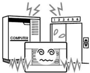
Ecn yctpoCTBO yctaHOBJeHO
PnDOM C KOMNbIOTepOM,
ABTomATnueCKmM DBePAMN,
JIuΦTOM NII O6OpyIOBaHHeM,
ReHepnpUoIm MwM, 3To
pNBoNT K HeHaJNeKaUe
paOte.
He yctaHaBnBaIte ceHTpaIbHbI nIyIbT ynpaBJIeHnB MecTx NOBbIeHHoB BlaxHoCTN CINbHbIX Bn6paqni.
EcIn yCTpoNCTBO yCTaHOBJeHO Ta, Ie OHO NOdBepraeTcB BO3DeIcTBIO BlaH, 6pbI3r BObl Nn CnIbHO BV6paun, 3TO npNBedeT K HeCnpabHOn pa6Ote.
I36eaiTe yCTaHOBKn YcTPOiCTBa B nPmblx COJIHeuHbIX IyauX IIN PraDM C NCTOCHKAMN TEJa.
Ecn yctpoCTBO yctaHOJEHO NOI npMbIMN COJHeHbIMN Jyamn nn pAOM C nCTOHNKOM TeNa, 3TO npBEdT K HeCnpabHo pa6oTe.
Poxkanynta,6paTnTecb K CBOemy DnIepy.
Borpocbi
No Bonpocam noclennpodaxkHoro 06cnyxmbaHn, 06patntecb K dInepy.

3rd Floor Thavies Inn House 3-4 Holborn Circus London EC1N 2HA, ENGLAND
Tel: +44-20-7842-8171
Fax: +44-20-7842-8104
http://www.mhie.com
三菱重工业(上海)有限公司
9C Commercial Road Kingsgrove NSW 2208 PO BOX 318 Kingsgrove NSW 1480
Tel: +61-2-8571-7977
Fax:+61-2-8571-7992
http://www.mhiaa.com.au
MITSUBISHI HEAVY INDUSTRIES - MAHAJAK AIR CONDITIONERS CO., LTD.
220 Lad Krabang Industrial Estate Free Zone 3,Soi Chalongkrung 31,Kwang Lamplatiew,
Khet Lad Krabang,Bangkok 10520,Thailand
Tel: +66-2-326-0401
Fax: +66-2-326-0419
[Select Group (Grup Segimi)ekrani]
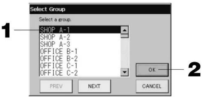
3rd Floor Thavies Inn House 3-4 Holborn Circus London EC1N 2HA, ENGLAND
Tel: +44-20-7842-8171
Fax:+44-20-7842-8104
http://www.mhie.com
三菱重工业(上海)有限公司
9C Commercial Road Kingsgrove NSW 2208 PO BOX 318 Kingsgrove NSW 1480
Tel: +61-2-8571-7977
Fax:+61-2-8571-7992
http://www.mhiaa.com.au
MITSUBISHI HEAVY INDUSTRIES - MAHAJAK AIR CONDITIONERS CO., LTD.
220 Lad Krabang Industrial Estate Free Zone 3,Soi Chalongkrung 31,Kwang Lamplatiew,
Khet Lad Krabang,Bangkok 10520,Thailand
Tel: +66-2-326-0401
Fax: +66-2-326-0419
- SC-SL3NA-BE (with Calculating Function)
- C
- Table of contents
- ENGLISH
- PRECAUTIONS FOR WASTE DISPOSAL
- Safety Precautions
- INSTALLATION PRECAUTIONS
- DANGER
- CAUTION
- OPERATION PRECAUTIONS
- PRECAUTIONS FOR RELOCATION OR REPAIR
- Warning
- Introduction
- Overview
- Names and Functions of Parts
- Blocks, Groups
- Startup Screen
- - ALL GROUPS Display
- - ALL BLOCKS Display
- Note
- Quick Reference Chart for Operations
- (*) Password
- Main Menu
- SYSTEM INFORMATION button
- System Configuration Screen
- UNITDEFINITIONbutton
- GROUP DEFINITION button
- BLOCKDEFINITIONbutton
- ACCOUNTING PERIOD button
- TIME&DATE SETTING button
- MENUButton
- Date and Time display
- HELP button
- STOP ALL button
- RUNALLbutton
- ALARM HISTORY button
- All Blocks Display
- - Individual Block Displays
- Icons
- Unit icon
- Filter sign
- Maintenance Indicator
- Scheduling
- Air direction
- Unit states
- Changeover Confirma rmination Screen
- Operation
- Attention
- Time & Date Setting
- Group Definition
- Press the DETAIL button.
- Press the CHANGE button.
- Press the ADD button.
- Press the DEL button.
- Press the REP. button
- Press the DEMAND button.
- Press the VALID or INVALID button.
- Press the SET button. Press the Yes button on the confirmation screen.
- Block Defi nition
- Select a block name.
- Group Operation Settings (Monitor Group Status)
- [BASIC GROUP SETTINGS screen]
- [Auto button enabled in Function Setting]
- Press the button for the item to set or change.
- Press the SET button. Press the Yes button on the confirmation screen.
- [DETAILS GROUP SETTINGS screen]
- [Individual lock / unlock settings enabled in Function Setting]
- Press the CHANGE button.
- Multiple Groups Operation Settings
- Group Batch Operation
- Press the CHANGE ALL button on the MAIN MENU. Page 7
- Press the button for item to set or change.
- Press the SET button. Press the Yes button on the confirmation screen.
- Schedule Settings
- Press the SCHEDULE SETTING button on the MAIN MENU. Page 7
- Setting the current day's schedule
- Press the group name.
- Press the item to be changed on the list.
- Select the detailed daily schedule such as WEEKDAY, HOLIDAY, SPECIAL 1 or SPECIAL 2 button and press it.
- Press the SET button. Press the Yes button on the confirmation screen.
- Setting a yearly schedule
- Press the YEARLY SCHEDULE button on the SCHEDULE SETTING screen.
- Select the detailed daily schedule such as ERATION button and press it.
- Press the date (multiple dates can be selected).
- Setting a detailed daily schedule
- Various screens
- Viewing Detailed Unit Information
- Calculating Settings (SC-SL3NA-BE only)
- ① Unit Defi nition
- Press the item to be set or changed on the list.
- ② Setting the period for calculation
- Press the hour or minute buttons for the start time or the end time.
- Convenient Functions
- Entering Numbers and Characters
- ■ Entering numbers
- ■ Entering characters
- Function Settings
- (Factory default :Valid)
- Press the "Valid" or "Invalid" button for the Individual Lock/Unlock. (Factory default: Invalid)
- Press the "Unlock" or "Lock" button for the Remote Controller's Timer. (Factory default: Unlock)
- Press the SET button.
- Corrections for Power Outages
- Using USB Memory
- Press the "Export monthly data files to USB" button.
- Press the folder to be selected.
- Press the OK button.
- Important!!
- Calculating Data
- Press IMPORT EXPORT button on the MAIN MENU. Page 7
- Press the "Export a configuration file to USB" button.
- Viewing Alarm History
- Press the date to be deleted.
- Press the DELETE button.
- Press the DELETE ALL button.
- System Information
- Help
- Maintenance
- Shut Down
- Troubleshooting
- Installation
- After Sales Service
- 三菱重工业(上海)有限公司
- MITSUBISHI HEAVY INDUSTRIES - MAHAJAK AIR CONDITIONERS CO., LTD.
- VOORZORGSGMAATREGELEN VOOR AFVALVERWERKING
- Planning
- Botão ACCOUNTING PERIOD
- (Periode de Registo)
- KaTaoTaon movadac
- Aioepwoeic oE TepiTTwon diaKoTnC pEuMaTOc
- Xpónση μνήμης USB
- Pnpooxn
- Σημειωη
- PpOBoLn IOTopIKoU TPOEIOIoiNcewV
- MEPbI PPEOCTOPOXHOCTN PPNYTNJIN3AUIN
- MepbI npeIoCTOpOxHocTn
- IMEPbI INPEOCTOPOXHOCTN IPN YCTAHOBKE
- ONACHOCTB
- OCTOPOXHO
- I MEPBI INPEDOCTOPOXHOCTN IPN PABOTE
- MEPbI PPEIOCTOPOXHOCTN IPN N3MEHEHIM MECTONOJOXEHHN IIN PEMOHTE
- BhimaHne!
- В级以上
- 0630p
- Ha3BaHnI ΦyHKcnn 3JIeMeHToB
- Блokи, рурпbli
- [πpimepbI coeHHeHH]
- HaçaλbHbɪŋ əKpaH
- euaHne
- - 3кразн ALL GROUPS (BCE Гупbl)
- - 3кразн ALL BLOCKS (BCE БлOKи)
- PnmuHaHne
- CnpaBoHna Ta6nua onepaun
- 3HaOK qInbTpα
- 3KpaH IOdTBepXdEHHa NepeKJIoueHHa
- Функциноюразионе
- BHMaHne
- HacrtpoiKa BpeMeHn I daTbI
- PpimMeaHne
- OnpeJeIeHne rpynn
- Bb6epute mma rpynnbl.
- Haxmte Khonky DETAIL (CBEDEHNA).
- Haxmnte KhoNky CHANGE (H3MEHHTb).
- TpimmeaHne
- PpMMeaHne
- HaxmTe KhOnky CHANGE (U3MEHHTb).
- PpIMeuaHne
- YcTaHOBKnpeXnMa pa6Otbl HeCKoJbKnx rpynn
- Haxmte KhONky COOTBeTCTByUoIero npaMeTpA dJI erO HAcTpOuK NII N3MeHeHnA.
- Haxmnte KhoNky SET. Ha 3KpaHe NOtBepKdEHHaXmTe Ha KhONKy "Yes" (Ja).
- KoMnJIeKcHbIe OnepaunC rpynnamn
- HaxMMTe KONKcy COOTBeTCTByUoIero npaMeTpA dIra erO HAcTpoIK NII N3MeHeHnR.
- Hac troponka pacnncanra
- B rnaBHOM MeHIO haxMnte KhoNky SCHEDULE SETTING (HACTPOUKA PACINCAHNA).
- Hactpoika pacnncahna Ha Tekyuyn DeHb
- Haxmte mma rpynnbl.
- B cπncke hαxMnte ha n3MeHЯEmbI npaMeTp.
- BbI6epnTe KhoNky WEEKDAY (DEHb HEDEJN), HOLIDAY (INPA3dHNK), SPECIAL 1 (OCOBbIM DEHb 1) nII N SPECIAL 2 (OCOBbl IN DEHb 2) nHaXmnte ee.
- PpMueHne
- HaxMMTe KONky SET. Ha 3Kpahe NOpTBePckDeHnHaXMMTe Ha KNONky "Yes" (Da).
- Bb6epnto np06hoe paoncaHne Ha deHb, Haxab KhoNky WEEKDAY (DEHb HEJIN), HOLIDAY (PNA3HNK), SPECIAL 1 (OCOBbl DEHb 1), SPECIAL 2 (OCOBbl DEHb 2) uN NO OPERATION (No OEPALUN).
- Haxmte daTy (MOXHO Bbl6paT HeckoJbKO daT).
- HaxMMTe KONky SET. Ha 3KpaHe NOtBepXeHnHa XMMTe Ha KHonky "Yes" (Ja).
- HactpoKa nOdpObHoro pacncaHnHa DeHb.
- Pa3nHbIe 3KpaHbI
- BHHMaHHe
- Поле3нble Функции
- BbOaIqdpN cIMBOJIOB
- BBoD uΦp
- BBOD CnMBOJIOB
- HactpoKaФyHKcN
- PnmuMeaHne
- YcTpaHHeHnE HApUWeHnE 3JleKTpOnNTaHnE
- IcnoJb30BaHne naMaTn USB
- BHHMaHne
- HaxmTe KhoNky "Export monthly data files to USB".
- Haxmte mR Bb6paHHo rpynnbl.
- HaxmTe KhoNky OK.
- PpimueaHne
- BaXHO!!
- Haxmte KhoNky "Export a configuration file to USB" (3Kcnpot faoJa konHpyaun B naMrtb USB).
- Ppocmotp cncka npednypeinteIbHbIX CNrHaIOB
- HΦopMaunO cnCTeme
- Cnpabka
- Овслужимbaне
- BbIKJIIOUHTb
- YcTpaHHeNHe HenCpabHocTei
Brand : MITSUBISHI
Model : SCSL3NAAE
Category : Air Conditioning