
PerfectCharge MCP1204 - Battery charger WAECO - Free user manual and instructions
Find the device manual for free PerfectCharge MCP1204 WAECO in PDF.

| Brand | Waeco |
| Model | PerfectCharge MCP1204 |
| Product type | Battery charger |
| Input voltage | 230 V~ |
| Maximum output current | 4.0 A |
| Absorption voltage (Mode 1) | 14.4 V |
| Absorption voltage (Mode 2) | 14.7 V |
| Float voltage | 13.8 V |
| Output voltage (Mode 3) | 13.7 V |
| Efficiency | up to 85% |
| Compatible battery types | Lead, gel, AGM, maintenance-free (12 V) |
| Recommended battery capacity | 7 – 110 Ah (charging), 7 – 180 Ah (maintenance) |
| Protection rating | IP65 |
| Operating temperature | -5 °C to +50 °C |
| Storage temperature | -20 °C to +70 °C |
| Dimensions (L x W x H) | 90 x 220 x 55 mm |
| Weight | 0.5 kg |
| Certifications | CE |
| Number of charging stages | 8 stages (desulfation, soft start, bulk, absorption, analysis, reconditioning, float, maintenance) |
| Charging modes | Mode 1 (14.4 V), Mode 2 (14.7 V), Mode 3 (13.7 V power supply) |
| Maintenance | Clean with a damp cloth; do not use abrasive products |
| Safety | Reverse polarity protection, 10 A fuse, automatic shutdown in case of fault |
| Repairability | Repairs by qualified personnel only; replaceable fuse |
Frequently Asked Questions - PerfectCharge MCP1204 WAECO
User questions about PerfectCharge MCP1204 WAECO
0 question about this device. Answer the ones you know or ask your own.
Ask a new question about this device
Download the instructions for your Battery charger in PDF format for free! Find your manual PerfectCharge MCP1204 - WAECO and take your electronic device back in hand. On this page are published all the documents necessary for the use of your device. PerfectCharge MCP1204 by WAECO.
USER MANUAL PerfectCharge MCP1204 WAECO
PerfectCharge MCP1204/1207
DE 6 Batterielader
Bedienungsanleitung
EN 25 Battery charger
Operating manual
| DE EN | FR ES IT | NL DA SV | ||||||
| bl Blau | Blue Bleu | Azul Blu | Blauw Blå | Blå | ||||
| gn Grün | Green Vert | Verde Verde | Verde Groen | Grøn Grön | ||||
| rt | RotNO FI | RedPT RU PL | RougeCS SK HU | Rojo | Rosso | Rood | Rød | Röd |
| bl Blå | Sini- nen | Azul Синий | Nie-bieski | Modrá | Modrá Kék | |||
| gn Grønn Vihreä | Verde | Зеле- ный | Ziel- ony | Zelená | Zelená Zöld | |||
| rt Rød | Punai- nen | Ver- melho | Крас- ный | Czer- wony | Čer- vená | Čer- vená | Piros | |
5
B
Please read this instruction manual carefully before first use, and store it in a safe place. If you pass on the product to another person, hand over this instruction manual along with it.
Table of contents
1 Explanation of symbols 26
2 General safety instructions 27
3 Scope of delivery 31
4 Accessories 31
5 Intended use 32
6 Technical description 32
7 Using the battery indicator 36
8 Using accessories 38
9 Caring for and cleaning the battery indicator 39
10 Troubleshooting 40
11 Warranty 41
12 Disposal 41
13 Technical data 42
1 Explanation of symbols

DANGER!
Safety instruction: Failure to observe this instruction will cause fatal or serious injury.

WARNING!
Safety instruction: Failure to observe this instruction can cause fatal or serious injury.

CAUTION!
Safety instruction: Failure to observe this instruction can lead to injury.

NOTICE!
Failure to observe this instruction can cause material damage and impair the function of the product.

NOTE
Supplementary information for operating the product.
▶ Action: This symbol indicates that action is required on your part. The required action is described step-by-step.
√ This symbol describes the result of an action.
Fig. 1 5, page 3: This refers to an element in an illustration. In this case, item 5 in figure 1 on page 3.
2 General safety instructions
2.1 General safety
The manufacturer accepts no liability for damage in the following cases:
● Faulty assembly or connection
● Damage to the product resulting from mechanical influences and excess voltage
- Alterations to the product without express permission from the manufacturer
● Use for purposes other than those described in the operating manual
Note the following basic safety information when using electrical devices to protect against:
Electric shock
- Fire hazards
- Injury
2.2 General safety

DANGER!
- In the event of fire, use a fire extinguisher which is suitable for electrical devices.

WARNING!
- Only use the device as intended.
- Ensure that the red and black terminals never come into contact.
- Disconnect the device from the mains.
– Before cleaning and maintenance - After use
– Before changing a fuse
- The device may not be used if the device itself or the connection cable are visibly damaged.
- If the power cable for this device is damaged, it must be replaced by the manufacturer, customer service or a similarly qualified person in order to prevent safety hazards.
- This appliance may only be repaired by qualified personnel. Inadequate repairs may cause serious hazards.
- The device may not be opened by improper means, as otherwise protection class IP65 can no longer be guaranteed.
- This device can be used by children aged 8 years or over, as well as by persons with diminished physical, sensory or mental capacities or a lack of experience and knowledge, providing they are supervised, or have been taught how to use the device safely and are aware of the resulting risks.
● Electrical devices are not toys.
Always keep and use the device out of the reach of children.
● Children must be supervised to ensure that they do not play with the device.

NOTICE!
- Before start-up, check that the voltage specification on the type plate is the same as that of the power supply.
- Ensure that other objects cannot cause a short circuit on the contacts of the device.
- Never pull the plug out of the socket by the connection cable.
● Store the device in a dry and cool place.
2.3 Safety when connecting the device electronically

DANGER! Danger of electrocution
● For connection on boats:
If electrical devices are incorrectly connected on boats, corrosion damage to the boat might occur. Have the device connected by a specialist (marine) electrician.
- If you are working on electrical systems, ensure that there is somebody close at hand who can help you in emergencies.

WARNING!
● Always use sockets which are grounded and secured by residual current circuit breakers.
● Make sure that the lead has a sufficient cross-section.
- Lay the cables so that they cannot be damaged by the doors or the bonnet.
Crushed cables can lead to serious injury.

CAUTION!
- Lay the cables so that they cannot be tripped over or damaged.
2.4 Operating the device safely

DANGER! Danger of electrocution
- Do not touch exposed cables with your bare hands. This applies especially when operating the device from the AC mains.
- To be able to disconnect the device quickly from the mains, the socket must be close to the device and be easily accessible.

WARNING!
- Only use the device in closed, well-ventilated rooms.
- Do not use the device with lead-acid batteries in enclosed spaces. These batteries give off explosive hydrogen gas that can be ignited by sparks on electrical connections.

CAUTION!
- Do not operate the device
– In salty, wet or damp environments
– In the vicinity of corrosive fumes
– In the vicinity of combustible materials
– In areas where there is a danger of explosions. - Before starting the device, ensure that the power supply line and the plug are dry.
● Always disconnect the power supply when working on the device. - Please observe that parts of the device may still conduct voltage even if the fuse has blown.
- Do not disconnect any cables when the device is still in use.

NOTICE!
- Ensure good ventilation.
2.5 Safety precautions when handling batteries

WARNING!
- Batteries contain aggressive and caustic acids. Avoid battery fluid coming into contact with your body. If your skin does come into contact with battery fluid, wash the part of your body in question thoroughly with water.
If you sustain any injuries from acids, contact a doctor immediately.

CAUTION!
- When working on the batteries, do not wear any metal objects such as watches or rings.
Lead acid batteries can cause short circuits which can cause serious injuries.
● Danger of explosions!
Never attempt to charge a frozen or defective battery.
Place the battery in a frost-free area and wait until the battery has acclimatised to the ambient temperature. Then start the charging process.
- Wear goggles and protective clothing when you work on batteries. Do not touch your eyes when you are working on the battery.
- Do not smoke and ensure that no sparks can arise in the vicinity of the engine or battery.

NOTICE!
- Only use rechargeable batteries.
- Prevent any metal parts from falling on the battery. This can cause sparks or short-circuit the battery and other electrical parts.
● Make sure the polarity is correct when connecting the battery.
- Follow the instructions of the battery manufacturer and those of the manufacturer of the system or vehicle in which the battery is used.
- If you need to remove the battery, first disconnect the earth connection. Disconnect all connections and all consumers from the battery before removing it.
3 Scope of delivery
| No. in fig. 1, Description page 3 |
| 1 Battery charger |
| 2 Connection cable with 12 V plug (cigarette lighter) |
| 3 Connection cable with cable lugs |
| 4 Connection cable with battery terminals |
| — Operating manual |
4 Accessories
Available as accessories (not included in the scope of delivery):
| Description Item no. | |
| Battery indicator(including connection cable with cable lugs) | 9102500078 |
| Wall bracket for the battery charger 9102500079 | |
5 Intended use
The battery charger (MCP1204: item no. 9102500070, MCP1207: item no. 9102500071) can charge or supply a float charge voltage to 12 V batteries used to generate power in vehicles or on boats.
The battery charger can be used on the following types of battery:
- Lead automotive batteries
- Gel batteries
● Fleece batteries (AGM)
● Maintenance-free batteries

NOTICE!
The battery charger may not be used on other types of batteries (e.g. NiCd, NiMH etc.) or defective batteries (e.g. with a cell short circuit).
The battery charger is only suitable for use indoors.
The battery charger is not suitable for mounting in one fixed place. The wall bracket (accessory; item no. 9102500079) must be used for this purpose.
6 Technical description
The battery charger charges batteries that are used as a source of voltage on board vehicles or boats, or supplies them with a float charge voltage to ensure they are not discharged.
The service life of most lead batteries is reduced by sulphation: lead sulphate forms into large, smooth crystals over the course of time and the amorphous, spongy structure disappears. The ability to recharge and therefore the charging capacity gradually decreases and the battery ages.
The battery charger operates using specific frequencies in parts of its charging curve. This causes the crystals to vibrate in their resonant frequency. They decompose into their amorphous structure. Their molecules can be integrated back into the charging process which in turn increases the charging voltage, starting current and the capacity of the battery again.
All lead batteries are protected from premature ageing by regular charging using the battery charger.
The battery charger can be operated in three operating modes:
- Mode 1: Charge mode with 14.4 V
This mode is used for lead, gel and maintenance-free batteries.
● Mode 2: Charge mode with 14.7 V This mode is used for AGM batteries. - Mode 3: Voltage supply with 13.7 V (battery is not connected) This mode is used as a power supply function, e.g. for supplying voltage to the vehicle in the event of replacing a battery, or during maintenance work using service devices.
The device can be installed on a wall using the wall bracket for stationary storage (accessory).
Furthermore, an external battery indicator (accessory) can be used. This shows the battery capacity and can be connected to the battery permanently using a connection cable with cable lugs. When it indicates the battery is empty, the battery charger can be connected to the battery indicator and the battery can be charged directly.
The battery indicator can be attached to a wall or to a wall bracket for the battery charger using a wall bracket.
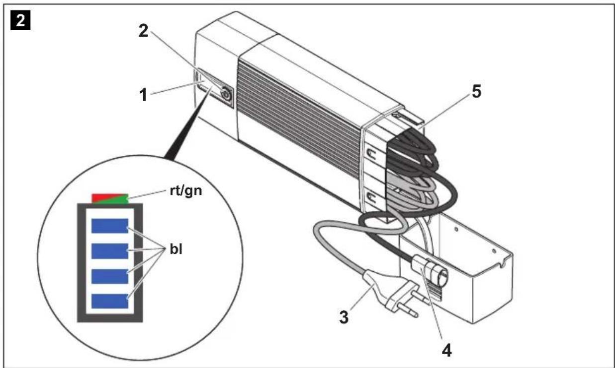
6.1 Control elements
No. in fig. 2, Designation Description page 3
| 1 Status LEDs See chapter “Status indications” on page 34 |
| 2 Pushbutton Selects the operating mode:Mode 1: Press button for 1 s(Battery is connected)Mode 2: Press button for 5 s(Battery is connected)Mode 3: Press button for 10 s(Battery is not connected) |
| 3 230 V cable Connection to mains voltage |
| 4 12 V cable Connection for the connection cable |
| 5 Cable compartment For storing the connection cable |
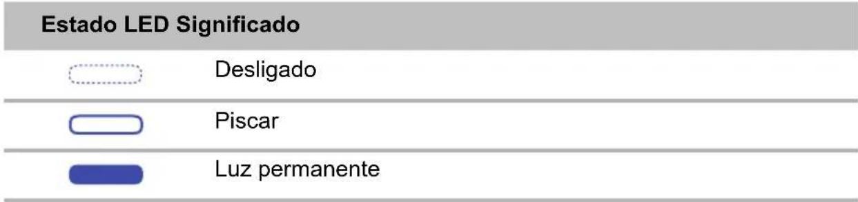
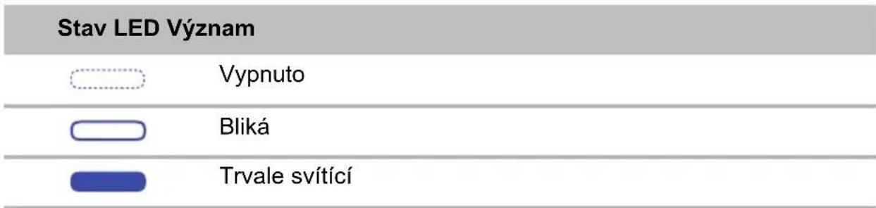
6.2 Status indications
Designation Description
Red LED Flashing: The polarity is incorrect, or the battery voltage is less than 9 V.
Constantly lit: The connection to the battery was disconnected during the charging process.
Green LED Constantly lit: Mode 1 or mode 3 is active.
Flashing: Mode 2 is active.
Blue LEDs In mode 1 and mode 2, the LEDs indicate the phase in which
the battery charger is currently operating (see the following table).
The LEDs flash in succession when the battery charger is operating in wait mode (the mains voltage is connected but the battery is not connected).
The LEDs flash simultaneously when the battery charger is ready for use (mains voltage is connected, battery is connected, button has not been pressed).
Meaning of the blue LEDs (mode 1 and 2)
Key to the figure:

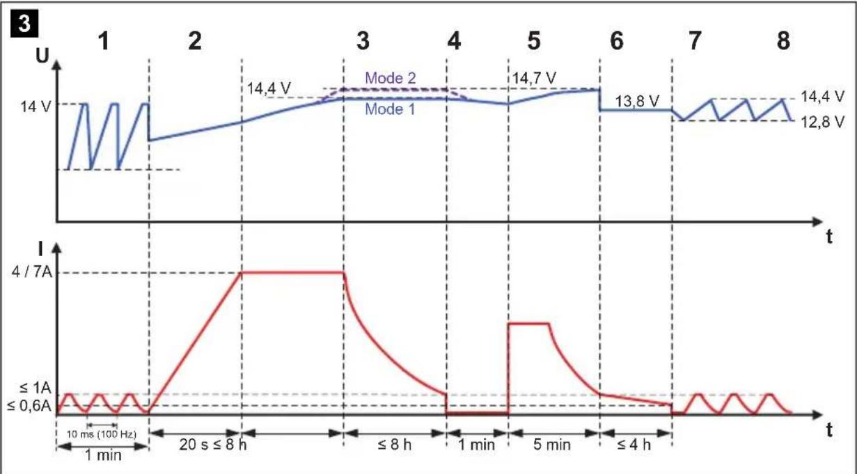
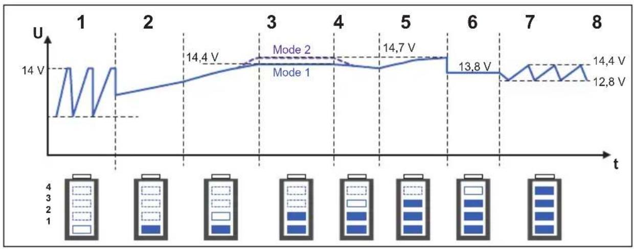
6.3 Battery charging function
The battery charger operates in eight phases (fig. 3, page 4).
1: Desulphation
Sulphated batteries are revived in the desulphation phase. The current and voltage pulse, so that sulphate is decomposed into its amorphous structure. The battery capacity is restored.
2: Soft start
The charging capability of the battery is tested using the power consumption in the soft-start phase. When the battery is defective, the charging process is aborted.
3: I phase (bulk)
The empty battery is charged with constant current (100 % charge current). As soon as the battery voltage has reached the charge voltage, the charge current decreases.
4: U0 phase (absorption)
The voltage remains constant during the U0 phase (U0). Once the battery is completely charged, the U0 phase has finished.
5: Analysis
The float charge of the battery is checked in the analysis phase. If the voltage drops too quickly, the battery can not retain the charge and must be replaced.
6: Reconditioning
The voltage is increased again in the reconditioning phase in order to generate controlled gas formation in the battery. This gas formation prevents acid stratification (different concentrations of acid in the battery cells).
7: U phase (float)
The battery switches to float charging in the U phase. The battery voltage is retained at 100 %.
8: Maintenance
In the maintenance phase, the charging voltage is switched off and the battery voltage is permanently measured. If it falls below 12.8 V, the battery charger charges the battery up to a maximum of 14.4 V. Then it switches the charging voltage off again and measures the battery voltage again.
This ensures secure winterizing, for example.
7 Using the battery indicator

NOTICE!
Make sure you do not reverse the polarity.
● Positive battery terminal: red terminal
● Negative battery terminal: black terminal
Incorrect polarity can damage the battery indicator.
7.1 Connecting the battery charger
▶ Check that the battery is in good condition:
▶ Check the following:
– The battery housing for damage
– The fluid level in the battery
Fill the battery with the medium specified by the manufacturer, if necessary.
- The pole contacts
Clean off any dirt present.
▶ Connect the power cable for the battery charger to the 230 V AC mains.
When you are using the connection cable with the 12 V plug: Switch the vehicle ignition on.
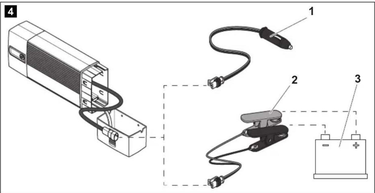
Connecting the battery charger to the battery (fig. 4, page 4)

NOTE
The connection cable with the 12 V plug is only suitable for use with Waeco cables and accessories.
▶ Insert the charging plug (1) into the 12 V--- socket (e.g. the cigarette lighter), or...
▶ ...connect the connection cable (2) to the battery (3) using the battery terminals, or to the battery charging points provided in the vehicle.
7.2 Using the battery charger
▶ Select the required mode:
Mode 1 (battery is connected): Press the button for 1 s.
Mode 2 (battery is connected): Press the button for 5 s.
Mode 3 (battery is not connected): Press the button for 10 s.
√ The charging process starts in mode 1 and 2.
A constant voltage supply is started in mode 3.
√ The LEDs show the charging progress of the battery of the battery charger (see chapter "Status indications" on page 34).
▶ To end the charging process, press the button once again.

NOTE
When the red LED flashes because the battery voltage is under 9 V, you can charge the battery to over 9 V in mode 3. To do this, disconnect the battery and switch to mode 3. Once the battery has been charged over 9 V, you can switch the battery charger to mode 1 or 2 again to start normal charging.
8 Using accessories

NOTE
Accessories are not included in the scope of delivery. If you have questions regarding the accessories, please contact your local service partner.
8.1 Storing the battery charger in the wall bracket
Installation instructions
When selecting the installation location for the wall bracket, observe the following information:
● The wall bracket must be installed in a location protected from moisture.
- The wall bracket may not be installed in areas containing flammable materials.
● The wall bracket may not be installed in dusty environments.
● The device must be installed on a level and sufficiently sturdy surface.
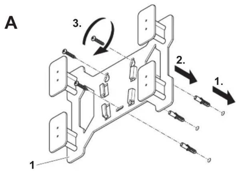
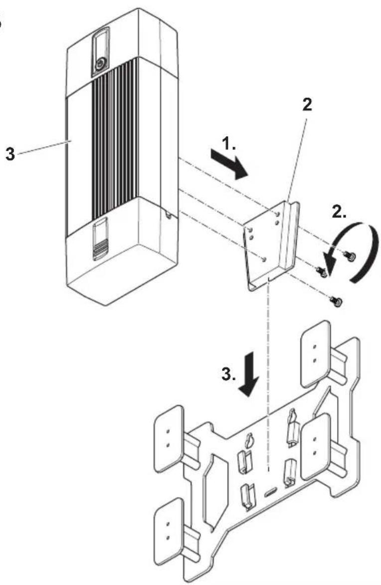
Installing the wall bracket
Install the wall bracket as follows (fig. 5, page 5):
▶ Attach the wall bracket (1) to the installation location you chose.
▶ Attach the adapter (2) to the battery charger (3).
Storing the battery charger
Store the battery charger as follows (fig. 5, page 5):
▶ Push the battery charger (3) along with the adapter into the cone-shaped brackets from above.
To release it, lift the battery charger upwards out of the brackets.
8.2 Using the battery charger with a battery indicator

NOTE
Notes on connection battery chargers to the battery indicator and on using the battery indicator can be found in the installation and operating manual for the battery indicator.
▶ Connect the battery charger to the battery indicator.
▶ Use the battery charger as described (see chapter “Using the battery charger” on page 37).
9 Caring for and cleaning the battery indicator

NOTICE!
Do not use sharp or hard objects or cleaning agents for cleaning as these may damage the product.
▶ Occasionally clean the product with a damp cloth.
10 Troubleshooting

WARNING!
Do not open the device. You risk sustaining an electric shock by doing this.

NOTE
If you have detailed questions about the battery charger data, please contact the manufacturer (addresses on the back of the instruction manual).
The red LED indicates a fault:
LED display Cause Remedy
Flashing Inverse polarity Check the cables and connections.
Flashing Battery voltage < 9 V The battery cannot be charged.
Replace the battery.
| Constantly lit Battery no longer connected | The connection to the battery was disconnected during the charging process.Check the cables and connections. |
| Fuse in the connection cable was tripped | Replace the fuse (10 A plug-in fuse for vehicles) |
11 Warranty
The statutory warranty period applies. If the product is defective, please contact the manufacturer's branch in your country (see the back of the instruction manual for the addresses) or your retailer.
For repair and guarantee processing, please include the following documents when you send in the device:
● A copy of the receipt with purchasing date
● A reason for the claim or description of the fault
12 Disposal
▶ Place the packaging material in the appropriate recycling waste bins wherever possible.
If you wish to finally dispose of the product, ask your local recycling centre or specialist dealer for details about how to do this in accordance with the applicable disposal regulations.
13 Technical data
| PerfectCharge MCP1204 | PerfectCharge MCP1207 | |
| Item no.: 9102500070 9102500071 | ||
| Rated input voltage: 230 V~ | ||
| Max. continuous output current: | 4.0 A ± 0.25 A 7.0 A | ± 0.5 A |
| Absorption voltage: 14.4 V ± 0.2 | V (mode 1) | |
| 14.7 V ± 0.2 V (mode 2) | ||
| Float voltage: 13.8 V ± 0.2 V | ||
| Output voltage in mode 3: 13.7 V ± 0.2 V | ||
| Maximum charging current: 4.0 A 7.0 A | ||
| Efficiency up to: 85 % | ||
| Type of batteries: 12 V batteries: | Lead automotive batteriesGel batteriesFleece batteries (AGM)Maintenance-free batteries | |
| Recommended battery capacities:Charge: 7 – 110 AhFloat charge: | 15 – 160 Ah7 – 180 Ah | 15 – 250 Ah |
| Protection class: | IP65 | |
| Ambient temperature for operation: | -5 °C to +50 °C | |
| Ambient temperature for storage | -20 °C to +70 °C | |
| Dimensions W x D x H: | 90 x 220 x 55 mm | 90 x 250 x 55 mm |
| Weight: | 0.5 kg | 0.7 kg |
| Certifications: | CE | |
6 Description technique
4: fase U0 (Absorption)
4: fase U0 (absorption)
6: Herconditionering (recondition)
1: Desulfatering (Desulphation)
4: U0-fase (Absorption)
4: U0-fas (absorption):
6: Rekonditionering (recondition)
8: Vedlikehold (Maintenance)
Selitys kuvaan:

6: Elvytys (Recondition)
Legenda da figura:
4: Fase U0 (Absorption)
8: Manutenção (Maintenance)
Piscar Polos Verifique os cabos e as conexões.
4: Faza U0 (Absorption)
Legenda k obrázku:
Legenda k obrázkom:

6.3 Funkcia nabíjania batérií
Nabíjačka batérií pracuje v ôsmich fázach (obr. 3, strane 4).
1: Desulfatácia (Desulphation)
Dometic Australia Pty. Ltd.
1 John Duncan Court
Varsity Lakes QLD 4227
1800 212121
+61 7 55076001
Mail: sales@dometic-waeco.com.au
AUSTRIA
Dometic Austria GmbH
The Gateway · 25 Canton Road,
Tsim Sha Tsui · Kowloon
+852 24611386
+852 24665553
Mail: info@dometic-waeco.com.hk
HUNGARY
Dometic Plc. Sales Office
Kerékgyártó u. 5.
H-1147 Budapest
+36 1 468 4400
昌 +36 1 468 4401
Dometic Italy S.r.l.
Via Virgilio, 3
I-47100 Forli
+39 0543 754901
+39 0543 756631
Mail: info@dometic.it
NORWAY
Dometic Norway AS
Skolmar 24
N-3232 Sandefjord
+47 33428450
吕 +47 33428459
Mail: firmapost@waeco.no
POLAND
Dometic Poland Sp. z o.o.
Ul. Puławska 435A
02-801 Warszawa
+48 22 414 32 00
+48 22 414 32 01
Mail: info@dometic.pl
RUSSIA
Dometic RUS LLC
Komsomolskaya square 6-1
107140 Moscow
+7 495 780 79 39
+7 495 916 56 53
Mail: info@dometic.ru
SLOVAKIA
Dometic Slovakia Sales Office Bratislava
Nádražná 34/A
SK-900 28 Ivanka pri Dunaji
+421 2 45 529 680
Mail: bratislava@dometic.com
SPAIN
Dometic Spain S.L.
Avda. Sierra del Guadarrama, 16
E-28691 Villanueva de la Cañada
Madrid
+34 902 111 042
+34 900 100 245
Mail: info@dometic.es
SWEDEN
Dometic Scandinavia AB
Gustaf Melins gata 7
Dometic Switzerland AG
Riedackerstrasse 7a
CH-8153 Rümlang (Zürich)
+41 44 8187171
吕 +41 44 8187191
Mail: info@dometic-waeco.ch
TAIWAN
WAECO Impex Ltd.
Taipei Office
9F.-10, No. 1180, Zhongzheng Rd.,
Zhonghe Dist., New Taipei City 23586
+886 2 22237225
昌 +886 2 81926742
Mail: marketing@waeco.com.tw
UNITED KINGDOM
Dometic UK Ltd.
Dometic House · The Brewery
Blandford St. Mary
Dorset DT11 9LS
+44 844 626 0133
昌 +44 844 626 0143
Mail: sales@dometic.co.uk
UNITED ARAB EMIRATES
Dometic Middle East FZCO
P. O. Box 17860
S-D 6, Jebel Ali Freezone
Dubai
+971 4 883 3858
+971 4 883 3868
Mail: info@dometic.ae
UNITED STATES OF AMERICA
Dometic Marine Division
2000 N. Andrews Ave. Extension
Pompano Beach, FL 33069 USA
+1 954 973 2477
+1 954 979 4414
Mail: marinesales@dometicusa.com

- PERFECTCHARGE MCP1204/1207
- TABLE OF CONTENTS
- 1 EXPLANATION OF SYMBOLS
- DANGER
- WARNING
- CAUTION
- NOTICE
- NOTE
- 2 GENERAL SAFETY INSTRUCTIONS
- 2.1 GENERAL SAFETY
- 2.2 GENERAL SAFETY
- 2.3 SAFETY WHEN CONNECTING THE DEVICE ELECTRONICALLY
- DANGER! DANGER OF ELECTROCUTION
- 2.4 OPERATING THE DEVICE SAFELY
- 2.5 SAFETY PRECAUTIONS WHEN HANDLING BATTERIES
- 3 SCOPE OF DELIVERY
- 4 ACCESSORIES
- 5 INTENDED USE
- 6 TECHNICAL DESCRIPTION
- 6.1 CONTROL ELEMENTS
- 6.2 STATUS INDICATIONS
- DESIGNATION DESCRIPTION
- 6.3 BATTERY CHARGING FUNCTION
- 1: DESULPHATION
- 2: SOFT START
- 3: I PHASE (BULK)
- 4: U0 PHASE (ABSORPTION)
- 5: ANALYSIS
- 6: RECONDITIONING
- 7: U PHASE (FLOAT)
- 8: MAINTENANCE
- 7 USING THE BATTERY INDICATOR
- 7.1 CONNECTING THE BATTERY CHARGER
- CONNECTING THE BATTERY CHARGER TO THE BATTERY (FIG. 4, PAGE 4)
- 7.2 USING THE BATTERY CHARGER
- 8 USING ACCESSORIES
- 8.1 STORING THE BATTERY CHARGER IN THE WALL BRACKET
- INSTALLATION INSTRUCTIONS
- INSTALLING THE WALL BRACKET
- STORING THE BATTERY CHARGER
- 8.2 USING THE BATTERY CHARGER WITH A BATTERY INDICATOR
- 9 CARING FOR AND CLEANING THE BATTERY INDICATOR
- 10 TROUBLESHOOTING
- 11 WARRANTY
- 12 DISPOSAL
- 6 DESCRIPTION TECHNIQUE
- 4: FASE U0 (ABSORPTION)
- 6: HERCONDITIONERING (RECONDITION)
- 1: DESULFATERING (DESULPHATION)
- 4: U0-FASE (ABSORPTION)
- 4: U0-FAS (ABSORPTION)
- 6: REKONDITIONERING (RECONDITION)
- 8: VEDLIKEHOLD (MAINTENANCE)
- 6: ELVYTYS (RECONDITION)
- 8: MANUTENÇÃO (MAINTENANCE)
- 4: FAZA U0 (ABSORPTION)
- 6.3 FUNKCIA NABÍJANIA BATÉRIÍ
- 1: DESULFATÁCIA (DESULPHATION)
- DOMETIC AUSTRALIA PTY. LTD
- AUSTRIA
- DOMETIC AUSTRIA GMBH
- HUNGARY
- DOMETIC PLC. SALES OFFICE
- DOMETIC ITALY S.R.L
- NORWAY
- DOMETIC NORWAY AS
- POLAND
- DOMETIC POLAND SP. Z O.O
- RUSSIA
- DOMETIC RUS LLC
- SLOVAKIA
- DOMETIC SLOVAKIA SALES OFFICE BRATISLAVA
- SPAIN
- DOMETIC SPAIN S.L
- SWEDEN
- DOMETIC SCANDINAVIA AB
- DOMETIC SWITZERLAND AG
- TAIWAN
- WAECO IMPEX LTD
- UNITED KINGDOM
- DOMETIC UK LTD
- UNITED ARAB EMIRATES
- DOMETIC MIDDLE EAST FZCO
- UNITED STATES OF AMERICA
- DOMETIC MARINE DIVISION
Brand : WAECO
Model : PerfectCharge MCP1204
Category : Battery charger