
CombiPower 2012 - Battery charger WAECO - Free user manual and instructions
Find the device manual for free CombiPower 2012 WAECO in PDF.

| Product type | Pure sine wave inverter with integrated automatic charger |
| Brand | Waeco |
| Model | CombiPower 2012 |
| Nominal input voltage | 12 V DC (range 10.5 - 16 V) |
| AC output voltage | 200 - 240 V AC programmable (230 V default) |
| Continuous output power | 2000 VA |
| Peak output power | 2300 VA for 3 minutes, 3000 VA for pulsing |
| Output frequency | 47 - 63 Hz programmable (50 Hz default) |
| Main charge current | 0 - 100 A (adjustable) |
| Secondary charge current | 5 A (3-step charger for small battery) |
| Compatible battery types | Lead-acid starting, gel, AGM, maintenance-free (not NiCd/NiMH) |
| Efficiency | > 87 % (12 V) |
| Overvoltage and undervoltage protection | Yes, programmable (OVP, UVP, UV Alarm) |
| Short circuit protection | Yes (automatic shutdown and restart) |
| Overheat protection | Yes, with power reduction and shutdown |
| Special functions | Power-Sharing, generator support, UPS, energy saving |
| Weight | 16.5 kg |
| Operating temperature | -25 °C to +40 °C (full load) |
| Operating humidity | 0 - 93 % (non-condensing) |
| Certifications | EN60950-1, directive 2009/19/EC, EN55022, EN55024, EN61000 |
| Warranty | Statutory (refer to manufacturer or dealer) |
Frequently Asked Questions - CombiPower 2012 WAECO
User questions about CombiPower 2012 WAECO
0 question about this device. Answer the ones you know or ask your own.
Ask a new question about this device
Download the instructions for your Battery charger in PDF format for free! Find your manual CombiPower 2012 - WAECO and take your electronic device back in hand. On this page are published all the documents necessary for the use of your device. CombiPower 2012 by WAECO.
USER MANUAL CombiPower 2012 WAECO
natural_image
Exterior view of a UDECO Combipower 2012 power supply unit (no visible text or symbols on the device body)WAECO CombiPower 2012, 2024
EN 60 Sine wave inverter with integrated
automatic charger
Installation Manual
We will be happy to provide you with further information about Dometic WAECO products. Please order our free catalogue with no obligation to buy on our homepage: www.dometic-waeco.com
F
natural_image
Stacked hard drive units with visible cooling fins and ventilation grilles (no text or symbols)CombiPower


CombiPower
natural_image
Pure electrical circuit diagram with resistor, diode, and ground symbol (no text or labels)


CombiPower
8
natural_image
Technical line drawing of an electronic device connected to a battery, showing internal components and wiring (no text or symbols)9
flowchart
graph TD
    A["Component 1"] --> B["Component 2"]
    B --> C["Component 3"]
    C --> D["Output"]
    style A fill:#f9f,stroke:#333
    style B fill:#ccf,stroke:#333
    style C fill:#cfc,stroke:#333
    style D fill:#fcc,stroke:#333


CombiPower
10
GND (2)
Batt Temp Sensor (3)
11
CombiPower
PC
CombiPower
flowchart
graph TD
    A["ENB"] --> B["Switch"]
    C["BAT+"] --> B
    B --> D["Ground"]


CombiPower
15
flowchart
graph TD
    A["Ig=XX.X Vg=XXX.X FQ=XX.X W=XXX"] <--> B["Ib=XXX °C = XX.X Vb=XX.X"]
    B <--> C["Li=XX.X Vi=XXX.X FQ=XX.X W=XX.X"]
    D["Charge Run Mode"] <--> E["Another Param"]
    E <--> F["P.S Mode Param"]
    G["COMBI Power On"] <--> H["CHR Power On"]
    H <--> I["Input Password"]
    J["Iac Setup"] <--> K["Power Sharing"]
    L["User Interface"] <--> M["I/P Parameter"]
    M <--> N["O/P Parameter"]
    N <--> O["Charge Parameter"]
    P["RST to Default"] <--> Q["User Interface"]
    R["LCD Contrast"] <--> S["LCD Auto-off"]
    T["Buzzer Setting"] <--> U["Alert Setting"]
    V["Shutdown Retry"] <--> W["Inv off Delay"]
    X["Language"] <--> Y["New Password"]
    Z["OVP Setting"] <--> AA["OVP Recovery"]
    AB["UVP Setting"] <--> AC["UVP Recovery"]
    AD["UV Alarm"] <--> AE["UV"]
    AF["O/P Voltage"] <--> AG["O/P Frequency"]
    AH["Sync Frequency"] <--> AI["Overload Alarm"]
    AJ["Saving Level"] <--> AK["Saving Interval"]
    AL["Ground Relay"] <--> AM["Saving Interval"]
    AN["Ibat Setup"] <--> AO["Second Charger"]
    AP["Max. Bulk Timer"] <--> AQ["Battery Type"]
CombiPower


CombiPower
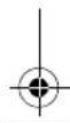
● PIN 3: -ENB, PIN 4: -VCC
line
| t | U/V (I/A) | |---|---| | 1 | Low | | 2 | High | | 3 | High | | 4 | High | | 5 | High | | 6 | High | | I | Low | | 6 | High |1: Analyse-Phase
3, 4: U0-Phase (Absorption)
5: U-Phase (Floating)
Please read this manual carefully before installing and using the device, and keep it in a safe place. If you sell the device, pass on this instruction manual to the buyer.
Table of contents
1 Notes on using the instruction manual. 61
2 General safety instructions 62
3 Target group for this manual 66
4 Scope of delivery 66
5 Intended use 66
6 Technical description 67
7 Connecting the device 81
8 Switching the device on and off 91
9 Configuring the device with the remote control ..... 91
10 Troubleshooting 99
11 Warranty 101
12 Disposal 101
13 Technical data 102


CombiPower Notes on using the instruction manual
1 Notes on using the instruction manual

DANGER!
Safety instruction: Failure to observe this instruction will cause fatal or serious injury.

WARNING!
Safety instruction: Failure to observe this instruction can cause fatal or serious injury.

CAUTION!
Safety instruction: Failure to observe this instruction can lead to injury.

NOTICE!
Failure to observe this instruction can cause material damage and impair the function of the product.

NOTE
Supplementary information for operating the product.
▶ Action: This symbol indicates that action is required on your part. The required action is described step-by-step.
√This symbol describes the result of an action.
fig. 1 5, page 3: This refers to an element in an illustration. In this case, item 5 in figure 1 on page 3.
Please observe the following safety instructions.


EN


General safety instructions CombiPower
2 General safety instructions
The manufacturer will not be held liable for claims for damage resulting from the following:
● Faulty assembly or connection
● Damage to the product resulting from mechanical influences and excess voltage
● Alterations to the product without express permission from the manufacturer
● Use for purposes other than those described in the operating manual
2.1 General safety

DANGER!
- Before you use the device for the first time, check that the operating voltage matches the mains voltage (see type plate).
- In the event of fire, use a fire extinguisher which is suitable for electrical devices.

WARNING!
- Do not use the device if the device itself or its connection cables are visibly damaged.
- This device may only be repaired by qualified personnel. Inadequate repairs may cause serious hazards.
Should your device need to be repaired, please contact customer services. - If a battery is connected, the device is live, even if the main switch is turned off.

CAUTION!
- If you disassemble the device:
- Set the main switch to "0".
- Detach all connections.
- Make sure that no voltage is present at any of the inputs and outputs.


CombiPower General safety instructions

NOTICE!
- Check that the voltage specification on the type plate is the same as that of the power supply.
- Ensure that other objects cannot cause a short circuit at the contacts of the device.
- Ensure that the red and black terminals never come into contact.
● Never pull the plug out of the socket by the cable.
2.2 Safety when installing the device

DANGER! Danger of electrocution
- For installation on boats:
If electrical devices are incorrectly installed on boats, corrosion damage might occur. Have the inverter installed by a specialist (marine) electrician.
- Do not touch exposed cables with your bare hands. This especially applies to all cables in the AC mains circuit.
- If you are working on electrical systems, ensure that there is somebody close at hand who can help you in emergencies.
- Never mount the device anywhere where there is a risk of gas or dust explosion.

WARNING!
- Only install the device in closed, well-ventilated rooms.
- Never install the device in rooms where materials that are fire hazards are stored, or where combustible gas is present; the surface temperature can reach 60 °C.
- Do not operate the device in systems with lead acid batteries. These batteries give off explosive hydrogen gas that can be ignited by sparks on electrical connections.
- Before starting the device, ensure that the power supply line and the plug are dry.
EN
General safety instructions CombiPower

CAUTION!
- Ensure that the device is standing firmly.
The device must be set up and fastened in such a way that it cannot tip over or fall down.
● Make sure that the device is earthed.
● Make sure that the lead has a sufficient cross-section. - Lay the cables so that they cannot be tripped over or damaged.
- Fasten the cables securely.
- Do not expose the device to a heat source (such as direct sunlight or heating). Avoid additional heating of the device in this way.

NOTICE!
- If cables have to be fed through metal walls or other walls with sharp edges, use ducts or bushings to prevent damage.
- Do not lay cables which are loose or bent next to electrically conductive material (metal).
- Do not pull on the cables.
- Do not lay the 230 V mains cable and the 12/24 V DC cable in the same duct.
- Set up the device in a dry location where it is protected against splashing water.
- Protect the device against corrosive fumes and salty or moist air.
● Protect the device and the cable against rain and moisture. - Ensure good ventilation.
● Only install the device indoors, never outside. - Do not connect the 230 V output of the inverter to a different 230 V source.
CombiPower General safety instructions
2.3 Safety precautions when handling batteries

WARNING!
- Batteries contain aggressive and caustic acids. Avoid battery fluid coming into contact with your body. If your skin does come into contact with battery fluid, wash the part of your body in question thoroughly with water.

CAUTION!
- Wear goggles and protective clothing when you work on batteries. Do not touch your eyes when you are working on the battery.
- When working on the batteries, do not wear any metal objects such as watches or rings.
Lead acid batteries can cause short circuits which can cause serious injuries. - Ensure that the device is standing firmly. The device and the batteries must be set up in such a way that they cannot tip over or fall down.
- Do not smoke and ensure that no sparks can arise in the vicinity of the engine or battery.

NOTICE!
- Only use rechargeable batteries.
- Make sure the polarity is correct when connecting the battery:
- Red terminal – positive battery terminal
- Black terminal – negative battery terminal
● Prevent any metal parts from falling on the battery. This can cause sparks or short-circuit the battery and other electrical parts. - Follow the instructions of the battery manufacturer and those of the manufacturer of the system or vehicle in which the battery is used.
● Never attempt to charge frozen batteries. - If you need to remove the battery, first disconnect the earth connection. Disconnect all connections and all consumers from the battery before removing it.
EN


Target group for this manual CombiPower
3 Target group for this manual
This manual is solely intended for qualified professionals who are familiar with the relevant VDE (German Engineering Society) regulations.
4 Scope of delivery
● Sine wave inverter with integrated automatic charger
● Battery temperature sensor with connection cable
● Remote control with connection cable
● Installation and operating manual
- Allen key
5 Intended use
Sine wave inverters with integrated automatic chargers are designed to convert 12 V or 24 V DC voltage to 230 V AC voltage with a frequency of 50 Hz, as well as to charge the following batteries:
● Lead automotive batteries
- Lead gel batteries
● Maintenance-free batteries
● Absorbed glass mat (AGM) batteries
Never use the devices to charge other battery types (such as NiCd or NiMH).

WARNING!
Do not use the device to power medical equipment.

WARNING! Danger of explosions
Do not charge batteries with a cell short circuit. The oxyhydrogen they produce can cause explosions.
Do not charge nickel cadmium and non-rechargeable batteries with the charger. The cases of these batteries can burst explosively.


CombiPower Technical description
6 Technical description
6.1 General description
The sine wave inverter with integrated automatic charger is a combination of two devices:
- Battery charger
- Sine wave inverter
The device can be used as follows:
● As an automatic charger (6-stage charging characteristic)
● As a sine wave inverter: the device produces a pure 230 V output voltage
● Power sharing: the device powers a connected load with 230 V and simultaneously charges a battery
- Generator function (mains voltage function): the device supports a 230 V mains voltage by supplementing it with energy from a battery (common power source)
● Power support (PSF): the device supports a 230 V mains voltage with energy from a battery by powering some of the loads from the battery and the others from the 230 V mains supply (separate power sources)
● Uninterruptible power supply (UPS): the device powers connected loads from a battery when the mains supply fails
The device has the following protective systems:
- DC low voltage shutdown
● DC overvoltage shutdown
● Overheating protection - Overload protection
The device is operated and configured using a remote control.
The device can also be configured with a PC via an RS 232 interface and using the DIP switches on the device.


EN


Technical description CombiPower
6.2 Connections and controls
No. in
fig. 1, page 3
Designation Explanation/function
1 POS (+) Positive terminal
2 NEG (−) Negative terminal
3 5A CHARGER/ 2.5A charger
5 A/2.5 A charger connection
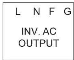
4 INV. AC OUTPUT 230 V inverter output
L: Live conductor
N: Neutral conductor
● FG: Earth connection
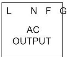
5 AC OUTPUT 230 V output
L: Live conductor
N: Neutral conductor
- FG: Earth connection
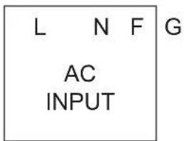
6 AC INPUT 230 V input
L: Live conductor
● N: Neutral conductor
- FG: Earth connection
7 - Cover
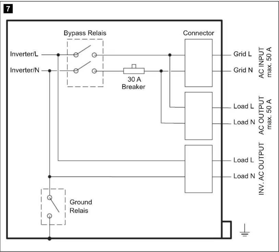
8 CIRCUIT BREAKER
LS: Circuit breaker (fig. 7, page 5) The circuit breaker is triggered when there is excess current or a short circuit.
▶Eliminate the cause of the fault.
▶Press the switch to reset the device.
9 CHASSIS GROUND
Earth connection
10 – Main switch:
0: Off
- 1: On
The main switch overrides the remote control settings. When the main switch is in the "0" position, you cannot switch on the device with the remote control.


EN


CombiPower Technical description
No. in
fig. 1, Designation Explanation/function page 3
11 CAN2 CAN bus connection
12 CAN1 CAN bus connection
13 LCM Remote control connection
14 RS-232 Serial RS-232 port for connecting to a PC
15 BAT. TEMP. Battery sensor connection
16 FAILURE Connection for fault indicator relay
17 INV CHR Connection for external switch


EN


Technical description CombiPower
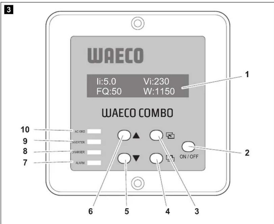
6.3 Remote control
No. in
fig. 3, Symbol Explanation/function page 4
1 – Display: Shows operating messages or settings
2 ON/OFF To switch on the device: press briefly
To switch off the device: hold down (> 3 s)
3 Scroll through menu (level up; vertical scroll)
4 Hold down (> 2 s): open setup menu
Press briefly: scroll through menu (level down; vertical scroll) or confirm value (ENTER function)
5 ▼Scroll through menu (back; horizontal scroll) or select a value
6 ▲Scroll through menu (forward; horizontal scroll) or select a value
7 ALARM LED for alarm display
- Red light: 230 V over/undervoltage alarm, 12 V over/undervoltage alarm, overload or fan malfunction
8 CHARGER Charging status LED:
● Green light: charging
- Off: not charging
9 INVERTER Inverter status LED:
● Green light: inverter mode
● Red light: inverter fault
- Off: inverter mode off
10 AC GRID Mains voltage status LED:
● Green light: AC voltage at input
● Off: no AC voltage at input
CombiPower Technical description
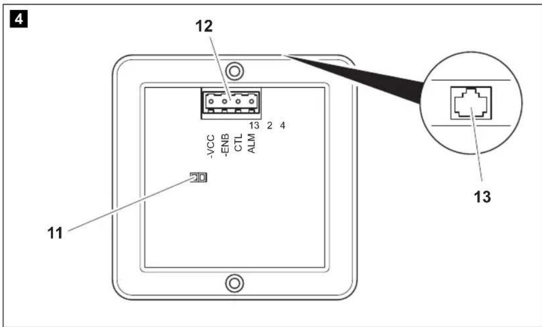
No. in
fig. 4, Symbol Explanation/function
page 4
11 – Jumper for activating or deactivating an external switch:
- Jumper open: external switch function deactivated
- Jumper inserted (factory setting): external switch function activated
12 - 4-pin plug
● PIN 1: ALM (alarm- function) not currently activated
- PIN 2: CTL
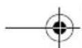
Depending on the jumper (fig. 4 11, page 4) the device can be forcibly switched on or off with a positive signal.
Jumper open:
CTL input voltage 5 - 60 V=== = ON
CTL input voltage 0 V=== = OFF
Jumper closed: CTL input voltage 5 - 60 V== = OFF CTL input voltage 0 V== = ON
- PIN 3: -ENB, PIN 4: -VCC The device can be switched on and off using these pins. No external voltage is required for this. -ENB is connected via a switch to -VCC (-VCC may not be connected to the negative terminal of the battery.) See fig. 6, page 5: Switch closed = device ON Switch open = device OFF Note: If the device is switched on using this function, it can be be switched off with the main switch only.
13 - Socket for remote control connection cable
EN

Technical description CombiPower
6.4 Status displays
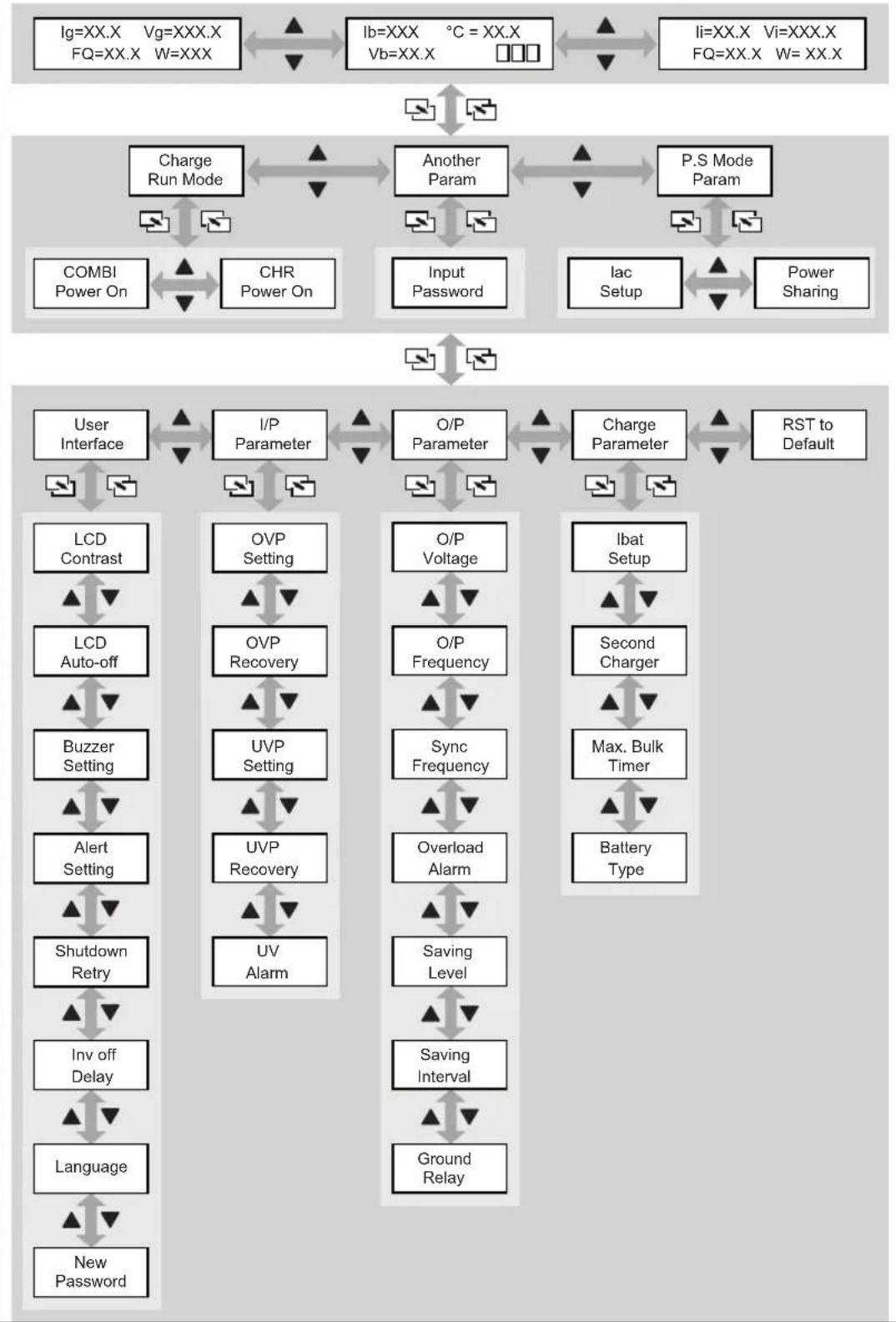
The status displays on the remote control (fig. 4 1, page 4) show the current device parameters. Use the “▼” and “▲” buttons to switch between the displays (fig. 15, page 9).
Symbol Explanation
| Ib Battery current |
| Ig Generator current |
| Ii Inverter current |
| Vb Battery voltage |
| Vg Generator voltage |
| Vi Inverter voltage |
| FQ Frequency (Hz) |
| W Power (watts) |
| °C Battery temperature |
□□□
Main battery charging phase
- battery not charging
- phase active
● □□□ phase active
● phase active


CombiPower Technical description
6.5 Battery charging function
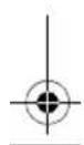
The charging characteristics are referred to as modified IU0U characteristics.
1: Analysis phase
First, the battery charge is analysed with increasing charge current.
2: I phase (bulk)
At the beginning of the charging process, the flat battery is charged with a constant current (100% charge current) until the battery voltage reaches 14.4 V or 28.8 V. The charging current decreases when the battery has reached this charging level.
3, 4: U0 phase (absorption)
Now the two-stage absorption charging process (U0-Phase) begins, where the charge voltage and duration depend on the size and type of the battery. Different voltages can be set for phases 3 and 4, which remain constant until the maximum charging current (6% of the set current) is reached.
Phase 4 ends no later than 8 hours after 13.8 V or 27.6 V is reached.
Technical description CombiPower
5: U Phase (floating)
The U phase serves to maintain the battery capacity (100%).
If DC loads are connected, they are powered by the device. Only if the power required exceeds the capacity of the device is this surplus power provided by the battery. The battery is then discharged until the device re-enters the I phase and charges the battery.
6: 14-day conditioning
Every 14 days, the battery charger switches back to phase 2 in order to revive the battery. This prevents any fatigue symptoms such as sulphation.
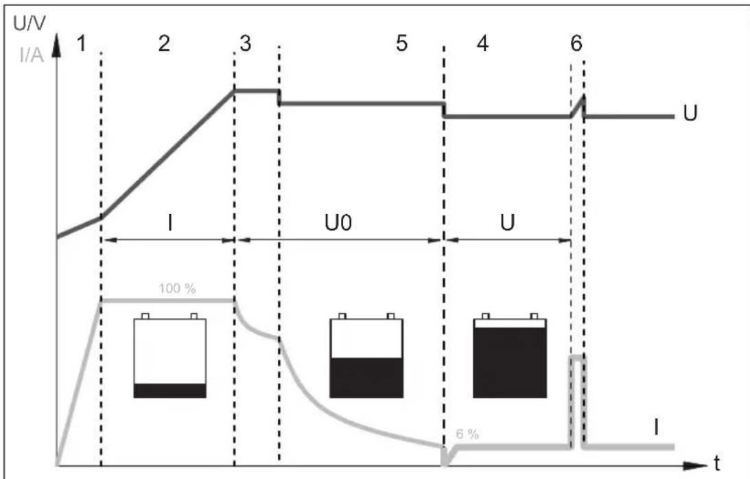
Charging with the battery temperature sensor
The battery temperature sensor supplied with the device needs to be connected. This adapts the charging voltage to the battery voltage. The charging voltage during the U0 phase is increased or reduced according to the battery temperature (see the following diagram):
line
| Time | 12 V | 24 V | |------|------|------| | -30 | 12 | 24 | | -20 | 12 | 24 | | -10 | 14.5 | 24 | | 0 | 14.5 | 24 | | 10 | 14.5 | 24 | | 20 | 14.5 | 24 | | 30 | 14.5 | 24 | | 40 | 14.5 | 24 | | 50 | 14.5 | 24 | | 60 | 14.0 | 24 | | 70 | 13.5 | 24 | | 80 | 13.0 | 24 | | 90 | 12.0 | 24 | | 100 | 12 | 24 |5 A/2.5 A charger (second battery connection)
The device has a connection for a second battery (3-step charger). You can charge a small battery (such as an automotive battery) using this connection.
The charging voltage is 14.4 ~V or 28.8 ~V . The maximum charging current is 5 ~A or 2.5 ~A .
CombiPower Technical description
6.6 Inverter function
In inverter mode, the device supplies a regulated 230 V voltage.
The maximum constant output is 2000 VA. Do not connect any devices with a higher power rating. If you connect several devices, make sure their total power rating does not exceed 2000 VA.

NOTE
Note when connecting devices with an electrical drive (such as power drills, refrigerators and switched-mode power supplies), that they often need more power than is stated on the type plate.
An adjustable energy saving mode protects the battery. It regularly checks whether battery power needs to be used. If not, the function is deactivated and no idle current is used.
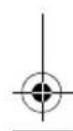
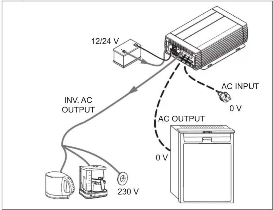
6.7 Connections
A battery is connected to the positive and negative terminals. A 230 V power source can be connected to the "AC INPUT" input (fig. 1 6, page 3). The power supply via "AC INPUT" takes precedence over the battery power supply, so that the battery is not discharged unnecessarily.
Voltage is present at the outputs under the following conditions:
● "INV. AC OUTPUT" (fig. 1 4, page 3)
– A battery is connected
- A 230 V power source is connected
- A battery and a 230 V power source are connected
(The battery is charged when the consumer devices do not require all the power)
● "AC OUTPUT" (fig. 1 5, page 3)
- A 230 V power source is connected


EN


Technical description CombiPower
6.8 Enabling functions
The device supports the functions described below.
Power sharing function
If the load from the connected consumer devices and the battery charging current is higher than the connected 230 V power source, the fuse of the power source would normally blow. In power sharing mode, the device reduces the battery charging current and thus increases the power available for connected consumers.
The power sharing level (current at the 230 V input) can be configured using the remote control. If must be adapted to the fuse of the power source. For example, if it has a 10 A fuse, the power sharing level must also be 10 A.
Example:
flowchart
graph TD
    A["12/24 V"] --> B["AC INPUT 230 V"]
    B --> C["AC OUTPUT"]
    C --> D["230 V"]
    D --> E["INV. AC OUTPUT"]
    E --> F["Device with fan icon"]


CombiPower Technical description
Generator function (external mains power supply)

NOTICE!
Observe the standards that apply in your country to the generator function.
If the load current is greater than the fuse of the connected 230 V power source, the fuse would normally blow. The generator function enables the device to provide additional power, which it takes from the battery.
If the required power falls below the power sharing level, the device recharges the battery.
In generator mode, the 230 V power source and the battery act as a common power source.
Example:
flowchart
graph TD
    A["12/24 V"] --> B["AC INPUT"]
    B --> C["230 V"]
    D["AC OUTPUT"] --> E["230 V"]
    F["INV. AC OUTPUT"] --> G["230 V"]
    H["Refrigerator"] --> I["Refrigerator"]
Technical description CombiPower
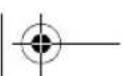
Power support function
If the generator function is not permitted by the standards in your country because the device operates in parallel to the 230 V mains, you can use the support function. The “AC OUTPUT” and “INV. AC OUTPUT” outputs are electrically isolated from each other.
The 230 V power source provides voltage at "AC OUTPUT" while the battery supplies "INV. AC OUTPUT".
If the devices connected to “INV. AC OUTPUT” require more current than the battery can deliver, they are switched off. If the devices connected to “AC OUTPUT” require more current than the set power sharing level (which must correspond to the fuse rating of the 230 V power source), the fuse of the 230 V power source blows. For example, if the power supply at a camp site has a 10 A fuse but the consumer devices required 16 A, the camp site fuse blows.
Example:
flowchart
graph TD
    A["Device"] -->|12/24 V| B["AC INPUT"]
    B -->|230 V| C["AC OUTPUT"]
    C -->|230 V| D["Reverter"]
    D -->|INV. AC OUTPUT| E["Reverter"]
    E -->|230 V| F["Reverter"]


CombiPower Technical description
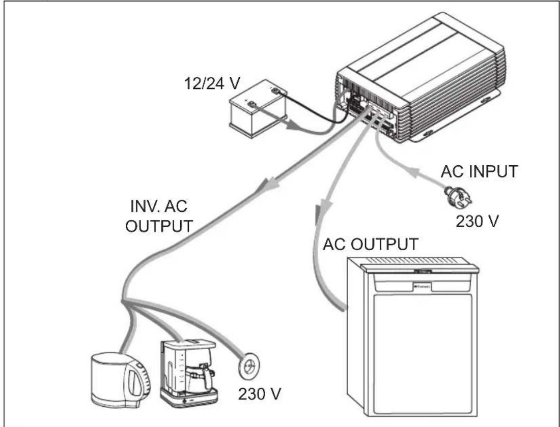
Uninterruptible power supply
The device can be used as an uninterruptible power supply. The device powers connected loads from a battery when the mains supply fails
You can use this function, for example, to continue running your air conditioning system if the 230 V power supply fails.

NOTE
You can use the remote control to configure how long the inverter continues operating after a mains power failure. This prevents the battery from deep discharging.
Example:


EN


Technical description CombiPower
Battery charger function
The connected battery is charged and conditioned if a 230 V power source is connected to "AC INPUT".
Example:

flowchart
graph TD
    A["12/24 V"] --> B["AC INPUT"]
    B --> C["230 V"]
    D["INV. AC OUTPUT"] --> E["AC OUTPUT"]
    E --> F["0 V"]
    G["Refrigerator"] --> H["0 V"]
    I["Refrigerator"] --> J["0 V"]

CombiPower Connecting the device
7 Connecting the device
7.1 Fastening the device
When selecting the installation location, observe the following instructions:
● The device can be mounted horizontally or vertically.
● The device must be installed in a place that is protected from moisture.
- Do not install the device near flammable materials.
- Do not install the device in a dusty environment.
- The place of installation must be well ventilated. A ventilation system must be present for installations in small, enclosed spaces. The clearance around the device must be at least 25 cm.
● The air inlet on the underside and the air outlet on the back of the device must remain clear.
- At ambient temperatures above 40 °C (for example in engine or heating rooms, or direct sunlight), the device reduces the power to prevent itself from overheating.
● The device must be installed on a level and sufficiently sturdy surface.
- Do not install the device in the same area as the batteries.
- Do not install the device above batteries, because they can emit corrosive sulphur fumes that will damage the device.

NOTICE!
Before drilling any holes, make sure that no electrical cables or other parts of the vehicle can be damaged by drilling, sawing and filing.
Fasten the device as follows:
▶Fasten the device with one screw through each hole in the holders.
Connecting the device CombiPower
7.2 Connecting the appliance
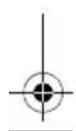
Connecting the battery (fig. 8, page 6)
Observe the following instructions when connecting the battery:
● Make sure the battery terminals are clean when connecting them.
- Make sure the connections are tight; tighten the fastening screw to 12–13 N m.
- Keep the cables as short as possible.
- Select a connection cable with a sufficient cross-section at a cable length up to 1.5 m:
- CombiPower 2012: ≥ 70 mm ^2
- CombiPower 2024: ≥ 50 ~mm^2
● Protect the positive terminal with a fuse:
- CombiPower 2012: 250 A
- CombiPower 2024: 125 A
- Lay the cables in accordance with VDE 100 (Germany).
- Connect the negative cable directly to the negative terminal of the battery, and not to the chassis of a vehicle or boat.
● Use the following cable colours:
- Red: positive connection
- Black: negative connection
- Do not reverse the polarity. If the polarity is incorrect, arcing will occur and damage the device.
Connect the "POS (+)" connection (fig. 1 1, page 3) to the positive terminal (+) of the battery.
▶ Connect the “NEG (−)” connection (fig. 1 2, page 3) to the negative terminal (−) of the battery.
Connecting the 5 A/2.5 A charger
The 5 A/2.5 A charger connection is used for a small battery such as an automotive battery. The 5 A/2.5 A charger charges the battery with a maximum current of 5 A or 2.5 A and a maximum voltage of:
● CombiPower 2012: 14.4 A
- CombiPower 2024: 28.8 A


CombiPower Connecting the device
Connect the positive terminal of the battery to the 5 A/2.5 A charger (fig. 1 3, page 3).
Use a conductor with a cross section of at least 2.5 mm^2 .
▶ Protect the positive terminal with a 7.5 A fuse.
▶ Connect the negative terminal of the battery to the negative terminal of the service battery.
Connecting the 230 V connections

WARNING!
The 230 V connections may only be made by qualified personnel.
Observe the following instructions when connecting to the mains:
- Select a connection cable of sufficient cross section for the maximum current:
- INV. AC OUTPUT: at least 2.5 ~mm^2
- AC OUTPUT, AC INPUT: at least 2.5 ~mm^2
For currents above 25 A, select an appropriate cross section.
- Use cables of the colours specified in the standards that apply in your country.
▶ Remove the cover (fig. 1 7, page 3).
▶Connect the required cables:
- INV. AC OUTPUT (fig. 1 4, page 3): 230 V output for inverter mode. Connect the devices you want to operate in inverter mode here.
Protect the circuit with a two-pole circuit breaker (MCB) or a residual current device.
- AC OUTPUT (fig. 1 5, page 3): 230 V output (max. 50 A)
Connect your 230 V devices here.
- AC INPUT (fig. 1 6, page 3): 230 V input (max. 50 A)
Connect your external 230 V power source here.
Protect the circuit with a fuse (the rating depends on the cable cross section) and either a two-pole circuit breaker (MCB) or a residual current device.
Connect the conductors according to fig. 9, page 6.
▶ Put the cover (fig. 1 7, page 3) back on.
EN


natural_image
Pure geometric diagram with crosshair and circular shapes without any text or symbolsConnecting the device CombiPower
Earthing the chassis
The metal housing of the device is connected internally to the neutral conductor and must therefore be connected to the chassis of the vehicle.
Connect the "CHASSIS GROUND" connection (fig. 1 9, page 3) to the vehicle chassis with a low-resistance electrical conductor.
Connecting the remote control
▶Plug one end of the remote control cable into the "LCM" connection (fig. 1 13, page 3).
Plug the other end of the remote control cable into the socket on the remote control (fig. 4 13, page 4).
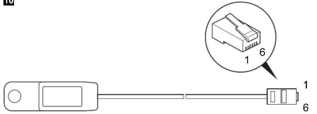
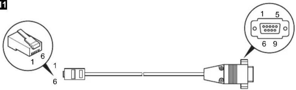
Connecting a PC
▶Plug the Western connector of the RS-232 cable into the "RS-232" connection (fig. 1 14, page 3).
▶Plug the serial connector of the RS-232 cable into the PC socket.
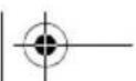
Connecting the battery sensor
Plug the battery sensor into the "BAT. TEMP." connection (fig. 1 15, page 3).
▶ Attach the battery sensor to the housing of the battery (fig. 8 2, page 6).
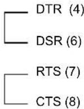
The cable wiring is as follows (fig. 10, page 7):
Pin no. Signal description
| 1 Not used |
| 2 Earth |
| 3 Battery sensor |
| 4 Not used |
| 5 Not used |
| 6 Not used |


CombiPower Connecting the device
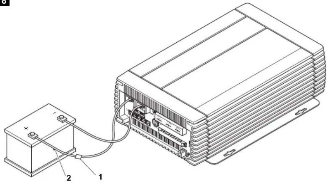
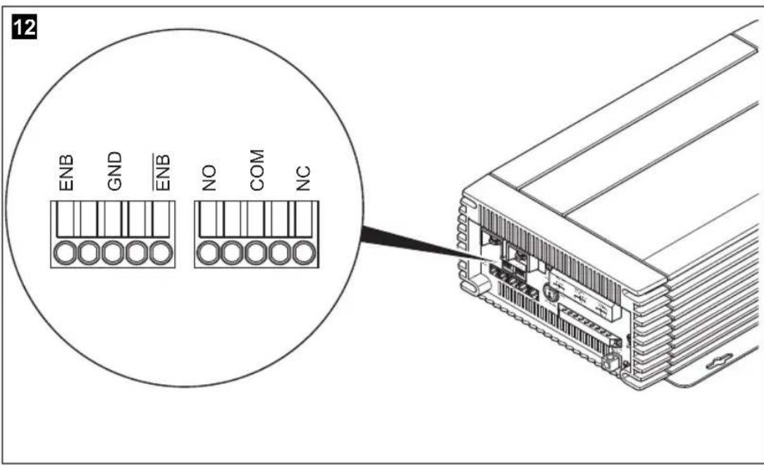
Connecting the fault display relay
If an alarm occurs, the (common) alarm contact switches to the normally open contact.
Connect the fault display relay as shown in fig. 12, page 8 to the "FAILURE" connection (fig. 1 16, page 3):
- NO: normally open contact
- COM: common contact
- NC: normally closed contact
Relay specification:
| Maximum voltage Load | Current consumptionNO NC | ||
| 250 V~ | Ohmic | 0.5 A | 0.5 A |
| 12 V/24 V== | Ohmic | 1 A | 1 A |
The following faults can be displayed:
● Undervoltage at input
● Overvoltage at input
● Short circuit at output
- Excess temperature
- Overload
- Fan failure
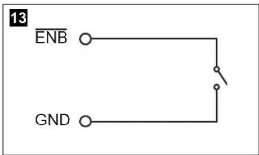
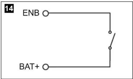
Connecting an external switch

NOTICE!
Only connect an external switch if you are not going to use the remote control (not normal operation).
Connect an external switch as shown in fig. 13, page 8 to fig. 14, page 8 to the "INV CHR" connection (fig. 1 17, page 3).
Use conductors with a cross section of at least 0.5 - 0.8 mm ^2 .
Key for fig. 13, page 8 to fig. 14, page 8:
• ENB Enable +
- ENB: Enable –
GND: Earth
Connecting the device CombiPower
7.3 Setting the DIP switches
You can adapt the device to the existing electrical system using the DIP switches SWA and SWB. The remote control settings take priority over the settings of the DIP switches (default settings).
▶ Remove the cover (fig. 1 7, page 3).

NOTICE! Beware of damage
The settings marked in the following table with the symbol ⚠ may only be carried out by experts.
▶Set the DIP switches as required.
The setting options for the DIP switches are shown on the following pages.
▶Restart the devices to store the values.
For this purpose switch off the main switch and switch it on again.
▶ Put the cover (fig. 1 7, page 3) back on.


CombiPower Connecting the device
SWA
The factory settings are highlighted in bold in the table.
Parameter Setting Switch position
| Energy-saving mode Off | |
| SWA 10 | |
| 40 VA | SWA 10 |
| 80 VA | SWA 10 |
| 100 VA | SWA 10 |
| 120 VA | SWA 10 |
| 160 VA | SWA 10 |
| 180 VA | SWA 10 |
| 220 VA | SWA 10 |
| Output voltage frequency △50 Hz | |
| SWA 10 | |
| 60 Hz | SWA 10 |


EN


Connecting the device CombiPower
Parameter Setting Switch position
| Output voltage △200 V | SWA | |
| 220 V | SWA | |
| 230 V | SWA | |
| 240 V | SWA | |
| Ground Relay ▲Determines whether the earth connection (fig. 19, page 3) is working. | Off | SWA |
| On | SWA | |
| Reset Resets the device to the original state. | Off | SWA |
| On | SWA |


CombiPower Connecting the device
SWB
The factory settings are highlighted in bold in the table.
Parameter Setting Switch position
| Support function Off | SWB | 10 | |
| On | SWB | 10 | |
| Generator function Off | SWB | 10 | |
| On | SWB | 10 | |
| Power sharing levelLimits the current at the 230 V input (overload protection). | 6 A | SWB | 10 |
| 10 A | SWB | 10 | |
| 16 A | SWB | 10 | |
| 25 A | SWB | 10 | |
| Power sharing Off | SWB | 10 | |
| On | SWB | 10 |


EN


Connecting the device CombiPower
Parameter Setting Switch position
| Battery types △ Battery type I | SWB | |
| Battery type II | SWB | |
| Battery type III | SWB | |
| Battery type IV | SWB | |
| Standard operating modeWith the “COMBI Power On” setting, the device acts as a charger and, when necessary, as an inverter if there is not enough power available at the AC input.With the “CHR Power On”, setting, the device only acts as a charger. The inverter function is deactivated. | COMBI Power On | SWB |
| CHR Power on | SWB |
| Battery type I Battery type II Battery type III | Battery type IV(Customer) | |||||||
| 12 V | 24 V | 12 V | 24 V | 12 V | 24 V | 12 V | 24 V | |
| I phase (bulk) charging voltage | 14,4 V | 28,8 V | 14,4 V | 28,8 V | 14,7 V | 29,6 V | 14 – 15 V | 28 – 30 V |
| U0 phase (absorption) charging voltage | 14,4 V | 28,8 V | 14,25 V | 28,5 V | 14,25 V | 28,5 V | 14 – 15 V | 28 – 30 V |
| U phase (floating) charging voltage | 13,5 V | 27,0 V | 13,8 V | 27.6 V | 13.6 V | 27,2 V | 13 – 14 V | 26 – 28 V |
CombiPower Switching the device on and off
8 Switching the device on and off

NOTE
The main switch (fig. 1 10, page 3) on the device must be in the "I" position.
▶ Press the "ON/OFF" button (fig. 3 2, page 4) on the remote control.
√ The device is switched on and the message "System Initialisation ..." appears in the display.
√ After a few seconds, the display shows the message "System startup please wait...".
The system status is checked.
√After 5 to 10 seconds, the display is ready and shows the status of the device:
- The device is ready for use: the display shows operating parameters.
- Alarm messages are present: undervoltage, overload, fan failure, overtemperature
– Faults have occurred: undervoltage (UVP), overvoltage (OVP), over-temperature (OTP), overload (OLP)
9 Configuring the device with the remote control
9.1 Basic information
Access to the "Another Param" menu, with which you can make the basic settings, is password-protected. The default password is "0000".
Opening setup mode
Switch on the device (see chapter "Switching the device on and off" on page 91).
▶ Press the “☐” button on the remote control for longer than 2 seconds.
√You are now in setup mode.
EN
Configuring the device with the remote control CombiPower
Selecting menus and parameters

NOTE
For the menu and parameter structure, see fig. 15, page 9.
▶Open setup mode.
▶ Use the “▼” or “▲” button to navigate to the required menu.
▶Press the “” button to select the menu.
▶ Use the “▼” or “▲” button to navigate to the required parameter.
▶Press the “” button to select the parameter.
▶ Use the “▼” or “▲” button to set the value for the parameter.
▶Briefly press the “” button to save the value.
Quitting setup mode
▶Press the “” button on the remote control.
Resetting all parameters to the original state
▶Open setup mode.
▶ Navigate to the "Another Param" menu.
▶Select the menu item "RST to Default".
▶Press the " " button to confirm.
√“ON” appears in the display.
▶Press the “” button again.
√ All parameters are reset to the original state.
CombiPower Configuring the device with the remote control
9.2 Overview of parameters
"Change Run Mode" menu (operating mode)
Parameter Explanation
COMBI Power On The device acts as a charger and, if necessary, as an inverter if there is not sufficient current at the AC input.
CHR Power On The device only acts as a charger. The inverter function is deactivated.
"P.S. Mode Param" menu (power sharing mode)
Parameter Explanation Value range Default
lac setup Power sharing level: limits the current at the 230 V input (overload protection). 3 A – 25 A 3 A
| Power Sharing | Determines the power sharing mode: | Disable | Disable |
| Disable = deactivated | SHAR. | ||
| GEN. = generator function | SHAR. GEN. | ||
| SUPP. = support function | SHAR. SUPP. | ||
| SHAR. = power sharing “SHAR.” enables the power sharing function. | SHAR. SUPP. GEN. | ||
| “SHAR. GEN.” enables the power sharing and generator functions. | |||
| “SHAR. SUPP.” enables the power sharing and support functions. | |||
| “SHAR. SUPP. GEN.” enables the power sharing, support and generator functions. |


EN


Configuring the device with the remote control CombiPower
"User Interface" menu (operating parameters)
| Parameter Explanation Value range Default | |||
| LCDcontrast | Sets the display contrast 0% – 100% 50 % | ||
| LCDAuto-off | Determines the time after whichthe display illumination isswitched off | 0 s – 250 s 120 sec. | |
| Buzzersetting | Specifies if and when the remotecontrol buzzer is activated:Disable= deactivatedMSG = Tone when switching onand every time a button ispressedAlert = Warning tone for fan fail-ure, undervoltage, overload orovertemperatureSHDN = Warning tone whenshutting down the device due toovervoltage, undervoltage, over-load or overtemperature | DisableSHDNAlertAlert, SHDNMSGMSG, SHDNMSG, AlertMsg, Alert, SHDN | Msg, Alert,SHDN |
| Alert setting | Determines the fault messagesthe relay should report (seechapter “Connecting the faultdisplay relay” on page 85):Disable= deactivatedAlert = Alarm for fan failure,undervoltage or overloadSHDN = Alarm for overvoltage,undervoltage, overload or over-temperature | DisableSHDNAlertAlert, SHDN | Alert,SHDN |
| ShutdownRetry | Determines how many times thedevice is automatically startedafter shutting down due to afault.(Disable = never) | Disable, 1– 15 5 | |

CombiPower Configuring the device with the remote control
| Parameter | Explanation | Value range | Default |
| Inv Off delay | Determines the time after which the device automatically switches from the 230 V supply to battery power. (Disable = never) | Disable, 1 – 10 min | Disable |
| Language Sets the display language English | Italian Spanish French German | English | |
| New Password | Specifies the password. The password consists of 4 digits. | 0000 – 9999 0000 | |
"I/P Parameter" menu (input parameters)
| Parameter | Explanation | Value range | Default |
| OVP Setting | Overvoltage at which inverter mode is deactivated | CombiPower 2012: 15 – 16 V--- | 16 V--- |
| CombiPower 2024: 30 – 32 V--- | 32 V--- | ||
| OVP Recovery | Voltage at which inverter mode is automatically reactivated after being deactivated due to over-voltage | CombiPower 2012: 13.5 – 14.5 V--- | 14.5 V--- |
| CombiPower 2024: 27 – 29 V--- | 29 V--- | ||
| UVP Setting | Undervoltage at which inverter mode is deactivated | CombiPower 2012: 10.5 – 11.5 V--- | 10.5 V--- |
| CombiPower 2024: 21 – 23 V--- | 21 V--- | ||
| UVP Recovery | Voltage at which inverter mode is automatically reactivated after being deactivated due to under-voltage | CombiPower 2012: 12.5 – 13.5 V--- | 12.5 V--- |
| CombiPower 2024: 25 – 27 V--- | 25 V--- | ||
| UV Alarm Voltage at which an undervolt-age alarm is triggered | CombiPower 2012: 10.5 – 11.5 V--- | 10.5 V--- | |
| CombiPower 2024: 21 – 23 V--- | 21 V--- | ||


EN


Configuring the device with the remote control CombiPower
"O/P Parameter" menu (output parameters)
| Parameter Explanation Value range Default | |||
| O/P Voltage | Output voltage | 200 V~ - 240 V~ | 230 V~ |
| O/P Frequency | Output voltage frequency 47 Hz - 63 Hz 50 Hz | ||
| Sync Frequency | Output voltage frequency tolerance for synchronisationIf the frequency tolerance is disabled, the output voltage frequency ranges between 47 and 63 Hz. | Disabled,0.1 Hz - 7 Hz | 7 Hz |
| Overload Alarm | Percentage power at which an overload alarm is triggered | 50% - 110% 100% | |
| Saving Level | Specifies the energy saving mode: minimum load for switching on againDisable = never1 = 40 VA2 = 80 VA3 = 100 VA4 = 120 VA5 = 160 VA6 = 180 VA7 = 220 VA | Disabled, 1 - 7 Disabled | |
| Saving Interval | Interval at which the system checks whether a consumer unit with the minimum load is switched on | 0.1 - 2 sec. | 2 sec. |


CombiPower Configuring the device with the remote control
Parameter Explanation Value range Default
| Ground Relay | Specifies whether the earth relay function is activated. If the earth relay function isactivated, the neutral conductor (N) of the inverter output circuit is automatically internally connected to the safety earth (PE/GND) when the device is operating as an inverter. If alternating current is supplied from an external 230 V power source, this connection is automatically disconnected.When the earth relay function is deactivated, there is no connection between the neutral conductor (N) and safety earth (PE/GND) when the device is operating as an inverter.Observe the regulations that apply in your country for this setting. | Auto ON Auto OFF | Auto OFF |

Configuring the device with the remote control CombiPower
"Charge Parameter" menu (output parameters)
| Parameter Explanation Value range Default | |||
| Ibat Setup Determines the charging current. | CombiPower 2012:20 – 100 A | 50 A | |
| CombiPower 2024:10 – 50 A | 25 A | ||
| Second charger | Determines whether the 5 A/2.5 A charger is switched on or off. | ON | ON |
| OFF | |||
| Max. Bulk timer | Determines how long the battery is charges in the I phase (bulk). | 8 – 18 h 8 h | |
| Battery type | Specifies the battery type.Standard = standard batteries (Battery type I)Acid = acid batteries (battery type II)GelAGM = Gel and AGM batteries (battery type III)Spiral = batteries with spiral cells (battery type III)Customer = customer values (battery type IV; according to manufacturer's recommendations)Information on the corresponding charging voltage is stored in the device. | StandardAcidGelAGM/SpiralCustomer | Standard |
| Battery type I Battery type II Battery type III | Battery type IV(Customer) | |||||||
| 12 V | 24 V | 12 V | 24 V | 12 V | 24 V | 12 V | 24 V | |
| I phase (bulk) charging voltage | 14,4 V | 28,8 V | 14,4 V | 28,8 V | 14,7 V | 29,6 V | 14 – 15 V | 28 – 30 V |
| U0 phase (absorption) charging voltage | 14,4 V | 28,8 V | 14,25 V | 28,5 V | 14,25 V | 28,5 V | 14 – 15 V | 28 – 30 V |
| U phase (floating) charging voltage | 13,5 V | 27,0 V | 13,8 V | 27.6 V | 13.6 V | 27,2 V | 13 – 14 V | 26 – 28 V |


CombiPower Troubleshooting
"RST to default" menu (original state)
Parameter Explanation
| RST to default | Resets the device to the original state (see chapter “Resetting all parameters to the original state” on page 92). |
10 Troubleshooting
Fault Cause Remedy
| No output voltage at “INV. AC OUTPUT” and “AC OUT- PUT” and no charging cur- rent; no LED lights up | The device is switched off Check the main switch | |
| The device is defective Replace the device | ||
| No contact to the battery Check the contact and cablesSwitch on the ignition if nec- essary | ||
| Battery discharged Charge the battery | ||
| Battery defective Replace the battery | ||
| Defective fuse (in the device or the vehicle) | Replace the fuse with one of the same rating | |
| No output voltage, “Alarm” LED lights up red, display shows “Overload Alert” | The device is at 100% load Reduce the load (switch off consumer units)Switch off the device and on again | |
| No output voltage, “Alarm” LED lights up red, display shows “UV Alert” | Battery voltage too low Charge the battery | |
| No output voltage, “Inverter” LED lights up red, display shows “OLP Shutdown” | Short circuitIncorrect wiring | Check the 230 V cable |
| Overload Reduce the load (switch off consumer units)Switch off the device and on again | ||
| No output voltage, “Inverter” LED lights up red, display shows “OLP Shutdown” | DC overvoltage Reduce the battery voltage or replace the battery | |
| No output voltage, “Inverter” LED lights up red, display shows “UVP Shutdown” | DC undervoltage | Check the cableCharge the battery |


EN


Troubleshooting CombiPower
Fault Cause Remedy
| No output voltage, “Inverter”LED lights up red, display shows “ENIR TEMP Shut-down” | Overheating Check the ventilation grillesand clean them if necessaryImprove the ventilationSet up the device somewhere cooler |
| No output voltage, “Inverter”LED lights up red, display shows “H.S. TEMP Shut-down” | |
| No output voltage, “Inverter”LED lights up red, display shows “BAT. TEMP Shut-down” | |
| No charging current Incorrect frequency Check the configured frequency | |
| No charging current, “Charger” and “AC Grid” LEDs are off | No 230 V power Check the 230 V power supplyCheck the wiring |
| No charging current, “Alarm” LED lights up red, display shows “UV Alert” | Overheating Switch off the consumer units.Let the inverter cool down and ensure better ventilation |
| The device constantly restarts | No connection to the battery Check the battery wiring |

NOTE
If you have detailed questions on the battery specifications, please contact the battery manufacturer.
CombiPower Warranty
11 Warranty
The statutory warranty period applies. If the product is defective, please contact the manufacturer's branch in your country (see the back of the instruction manual for the addresses) or your retailer.
For repair and guarantee processing, please include the following documents when you send in the device:
● A copy of the receipt with purchasing date
● A reason for the claim or description of the fault
12 Disposal
▶Place the packaging material in the appropriate recycling waste bins wherever possible.
If you wish to finally dispose of the product, ask your local recycling centre or specialist dealer for details about how to do this in accordance with the applicable disposal regulations.


EN


Technical data CombiPower
13 Technical data
General technical data
| CombiPower 2012 CombiPower 2024 | ||
| Item no. 9102600104 9102600105 | ||
| Heat dissipation Housing/fan | ||
| Ambient temperature at full load -25 °C | - +40 °C | |
| Ambient temperature for storage -30 °C | - +70 °C | |
| Power derating 50 W/°C, 41 °C - 60 °C | ||
| Air humidity 0 - 93%, non-condensing | ||
| Bypass relay 25 A, 250 V~ | ||
| Earth relay Supplied for earthing the neutral conductor in inverter mode, deactivated by default | ||
| Power sharing function Inverter mode, charging mode, power sharing (power sharing, generator function (mains voltage function), power support) | ||
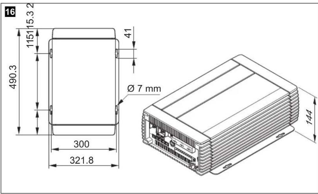
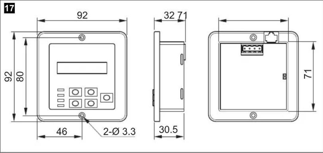
| Dimensions | see fig. 16, page 10 | |
| Weight | 16.5 kg | |
| Testing/certification | EN60950-1CE e 13According to 2009/19/EC (2004/104/EC) directive, EMC directive for motor vehiclesEN55022: 1998 + A1: 2000 + A2: 2003Class AEN55024: 1997 + A1: 2001 + A2: 2003EN61000-3-2: 2006 Class AEN61000-3-3: 1995 + A1: 2001 | |


CombiPower Technical data
Input data
| CombiPower 2012 CombiPower 2024 | ||
| Rated input voltage | 12 V--- | 24 V--- |
| Input voltage range | 10.5 – 16 V--- | 21 – 32 V--- |
| Input overvoltage protection | 15 – 16 V--- | 30 – 32 V--- |
| Input undervoltage protection(programmable) | 10.5 – 11.5 V---21 | - 23 V--- |
| Idle current consumption 5 A 2.5 A | ||
| Standby current consumption 1.5 A 0.75 A | ||
Output data
| CombiPower 2012 CombiPower 2024 | ||
| Output voltage (programmable) 200 – 24 | 0 V~ ±5% | |
| Constant output power | 2000 VA | |
| Frequency (programmable) | 47 – 63 Hz ±0.01% | |
| Peak output power | 2300 VA for up to 3 min3000 VA pulse power | |
| Efficiency | >87% at 12 V--- | >88% at 24 V--- |
| Short circuit protection | Yes, Ipk | |
| Wave form | Pure sine wave,maximum 3% distortion | |
Protective devices
| CombiPower 2012 CombiPower 2024 | |
| DC battery connection | Input fuse |
| AC inverter output | Power-regulated inverter30 A fuse to for AC input |
| AC output | None |
| AC input | 30 A fuse to battery charger |
| Battery protection | Temperature sensor on battery |


EN


Technical data CombiPower
AC INPUT technical data
| CombiPower 2012 CombiPower 2024 | ||
| Rated input voltage 230 V~ | ||
| Frequency 50 Hz | ||
| Input voltage range 180 – 260 V~ | ||
| Frequency range 47 – 63 Hz | ||
| Rated current 7.4 A (at 230 V) | ||
| Power factor correction >98% (40% load) | ||
Technical data for charging
| CombiPower 2012 CombiPower 2024 | ||
| Charging current 0 – 100 A 0 – 50 A | ||
| Charging current of second battery connection | 5 A, 3-step charger | 2.5 A, 3-step charger |
| I phase (bulk) charging voltage^1) | 14.4 V 28.8 V | |
| U0 phase (absorption) charging voltage^1) | 14.4 V 28.8 V | |
| U phase (floating) charging voltage^1) | 13.5 V 27 V | |
| Battery temperature compensation | -25 mV/°C | -50 mV/°C |
1) Values apply for the setting "Battery type = Standard" (Menu "Charge Parameter")
CombiPower Technical data
Messages
| CombiPower 2012 CombiPower 2024 | |
| Remote control Two-line display | KeypadLEDs: red, green, orange |
| Remote control Controls ON/OFF mode | |
| Floating contact With relay | |
| Fan mode Faults reported with alarm signal | Speed-regulated according to load and temperature |
Connection current values
| CombiPower 2012 CombiPower 2024 | ||
| INV. AC OUTPUT Max. 25 A | ||
| AC OUTPUT Max. 50 A | ||
| AC INPUT Max. 50 A | ||
Different versions, technical modifications and delivery options reserved.


CombiPower
Description technique CombiPower
6 Description technique
CombiPower Description technique
Description technique CombiPower
Pos. dans
fig. 1,
Désignation
CombiPower Description technique
6.3 Télécommande
Pos. dans
fig. 3, Symbole Explication/fonction page 4
Description technique CombiPower
Pos. dans
CombiPower Description technique
Description technique CombiPower
3, 4: Phase U0 (absorption)
CombiPower Description technique
5: Phase U (Floating)
Description technique CombiPower
CombiPower Description technique
6.7 Raccordements
Description technique CombiPower
CombiPower Description technique
Description technique CombiPower
Fonction Power-Support
CombiPower Description technique
Alimentation sans interruption
Description technique CombiPower
natural_image
Pure geometric diagram with crosshair and circular shapes without any text or symbolsN° PIN (borne) Description du signal
● PIN 3: -ENB, PIN 4: -VCC
3, 4: Fase U0 (Absorption)
natural_image
Pure geometric diagram with crosshair and circular shapes without any text or symbolsflowchart
graph TD
    A["12/24 V"] --> B["AC INPUT"]
    B --> C["230 V"]
    D["AC OUTPUT"] --> E["230 V"]
    F["INV. AC OUTPUT"] --> G["Device with fan icon"]
    H["Device with fan icon"] --> I["Device with bulb icon"]


natural_image
Pure geometric diagram with crosshair and circular shapes without any text or symbolsDatos técnicos CombiPower
13 Datos técnicos
natural_image
Pure geometric diagram with crosshair and circular shapes without any text or symbolsnatural_image
Pure geometric diagram with crosshair and circular shapes without any text or symbols- PIN 3: -ENB, PIN 4: -VCC
natural_image
Pure geometric diagram with crosshair and circular shapes without any text or symbols①Dometic Italy S.p.A.
Via Virgilio, 3
I-47100 Forli
+39 0543 754901
+39 0543 756631
Mail: info@dometic.it
Overseas + Middle East
AUS Dometic Australia
1 John Duncan Court
Varsity Lakes QLD 4227
+61 7 55076000
+61 7 55076001
Mail: sales@dometic-waeco.com.au
CH Dometic Switzerland AG
Riedackerstrasse 7a
CH-8153 Rümlang (Zürich)
+41 44 8187171
吕 +41 44 8187191
Mail: info@dometic-waeco.ch
N Dometic Norway AS
Skolmar 24
N-3232 Sandefjord
+47 33428450
吕 +47 33428459
Mail: firmapost@waeco.no
(HK) WAECO Impex Ltd.
Suites 2207-2211 · 22/F · Tower 1
The Gateway · 25 Canton Road,
Tsim Sha Tsui · Kowloon
Hong Kong
+852 24611386
+852 24665553
Mail: info@dometic-waeco.com.hk
DK Dometic Denmark A/S
Nordensvej 15, Taulov
DK-7000 Fredericia
+45 75585966
吕 +45 75586307
Mail: info@waeco.dk
NL Dometic Benelux B.V.
Ecustraat 3
NL-4879 NP Etten-Leur
+31 76 5029000
吕 +31 76 5029090
Mail: info@dometic.nl
ROC WAECO Impex Ltd.
Taipei Office
2 FL-3 · No. 56 Tunhua South Rd, Sec 2
Taipei 106, Taiwan
+886 2 27014090
+886 2 27060119
Mail: marketing@dometic-waeco.com.tw
E Dometic Spain S.L.
Avda. Sierra del Guadarrama, 16
E-28691 Villanueva de la Cañada
Madrid
+34 902 111 042
+34 900 100 245
Mail: info@dometic.es
s Dometic Scandinavia AB
Gustaf Melins gata 7
Regional Office Middle East
P O Box 74775
Dubai, United Arab Emirates
+971 4 321 2160
+971 4 321 2170
Mail: info@dometic.ae
F Dometic S.N.C.
Dometic House · The Brewery
Blandford St. Mary
Dorset DT11 9LS
+44 844 626 0133
+44 844 626 0143
Mail: sales@dometic.co.uk
USA Dometic Marine Division
2000 N. Andrews Ave. Extension
Pompano Beach, FL 33069 USA
+1 954 973 2477
+1 954 979 4414
Mail: marinesales@dometicusa.com
FIN Dometic Finland OY
Mestarintie 4
FIN-01730 Vantaa
+358 20 7413220
吕 +358 9 7593700
Mail: info@dometic.fi
www.dometic-waeco.com


- WAECO CombiPower 2012, 2024
- F
- CombiPower
- 15
- 1: Analyse-Phase
- 3, 4: U0-Phase (Absorption)
- 5: U-Phase (Floating)
- Table of contents
- Notes on using the instruction manual
- DANGER!
- WARNING!
- CAUTION!
- NOTICE!
- NOTE
- General safety instructions
- General safety
- CombiPower General safety instructions
- Safety when installing the device
- DANGER! Danger of electrocution
- - For installation on boats:
- General safety instructions CombiPower
- Safety precautions when handling batteries
- Target group for this manual
- Scope of delivery
- Intended use
- WARNING! Danger of explosions
- Technical description
- General description
- Connections and controls
- CombiPower Technical description
- Remote control
- Status displays
- Battery charging function
- 1: Analysis phase
- 2: I phase (bulk)
- 3, 4: U0 phase (absorption)
- 5: U Phase (floating)
- 6: 14-day conditioning
- Charging with the battery temperature sensor
- A/2.5 A charger (second battery connection)
- Inverter function
- Connections
- Enabling functions
- Power sharing function
- Generator function (external mains power supply)
- Example:
- Technical description CombiPower
- Power support function
- Uninterruptible power supply
- Battery charger function
- Connecting the device
- Fastening the device
- Connecting the appliance
- Connecting the battery (fig. 8, page 6)
- Connecting the 5 A/2.5 A charger
- CombiPower Connecting the device
- Connecting the 230 V connections
- Connecting the device CombiPower
- Earthing the chassis
- Connecting the remote control
- Connecting a PC
- Connecting the battery sensor
- Connecting the fault display relay
- Connecting an external switch
- Setting the DIP switches
- NOTICE! Beware of damage
- SWA
- SWB
- Switching the device on and off
- Configuring the device with the remote control
- Basic information
- Opening setup mode
- Selecting menus and parameters
- Quitting setup mode
- Resetting all parameters to the original state
- Overview of parameters
- Parameter Explanation
- "P.S. Mode Param" menu (power sharing mode)
- Parameter Explanation Value range Default
- CombiPower Troubleshooting
- "RST to default" menu (original state)
- Troubleshooting
- Troubleshooting CombiPower
- CombiPower Warranty
- Warranty
- Disposal
- Technical data
- CombiPower Technical data
- Description technique
- Description technique CombiPower
- Pos. dans
- Télécommande
- fig. 3, Symbole Explication/fonction page 4
- 3, 4: Phase U0 (absorption)
- 5: Phase U (Floating)
- CombiPower Description technique
- Raccordements
- Fonction Power-Support
- Alimentation sans interruption
- 3, 4: Fase U0 (Absorption)
- Datos técnicos
- Overseas + Middle East
Brand : WAECO
Model : CombiPower 2012
Category : Battery charger