ARX25K2V1B - Air-conditioner DAIKIN - Free user manual and instructions
Find the device manual for free ARX25K2V1B DAIKIN in PDF.
| Brand | Daikin |
| Model | ARX25K2V1B |
| Product type | Split air conditioner |
| Cooling capacity | 2.5 kW |
| Heating capacity | 2.8 kW |
| Refrigerant | R410A |
| Power supply | 230 V / 50 Hz, single phase |
| Noise level | Below 70 dB(A) |
| Max. pipe length | 15 m |
| Main functions | Cooling, heating, dehumidification, ventilation |
| Heat pump | Yes |
| Maintenance | Regular filter cleaning |
| Safety | Mandatory grounding, earth leakage circuit breaker |
| Installation | Only by qualified professional |
| Outdoor unit weight | Approximately 30 kg (estimate) |
Frequently Asked Questions - ARX25K2V1B DAIKIN
User questions about ARX25K2V1B DAIKIN
0 question about this device. Answer the ones you know or ask your own.
Ask a new question about this device
Download the instructions for your Air-conditioner in PDF format for free! Find your manual ARX25K2V1B - DAIKIN and take your electronic device back in hand. On this page are published all the documents necessary for the use of your device. ARX25K2V1B by DAIKIN.
USER MANUAL ARX25K2V1B DAIKIN
Installation manual R410A Split series
- Read these Safety Precautions carefully to ensure correct installation.
- This manual classifies the precautions into WARNING and CAUTION.
Be sure to follow all the precautions below: they are all important for ensuring safety.
WARNING.....Failure to follow any of WARNING is likely to result in such grave consequences as death or serious injury.
CAUTION .......Failure to follow any of CAUTION may result in grave consequences in some cases.
- The following safety symbols are used throughout this manual:

Be sure to observe this instruction.

Be sure to establish an earth connection.

Never attempt.
- After completing installation, test the unit to check for installation errors. Give the user adequate instructions concerning the use and cleaning of the unit according to the Operation Manual.
- The English text is the original instruction. Other languages are translations of the original instructions.

WARNING
- Installation should be left to the dealer or another professional. Improper installation may cause water leakage, electrical shock, or fire.
Install the air conditioner according to the instructions given in this manual. Incomplete installation may cause water leakage, electrical shock, or fire. - Be sure to use the supplied or specified installation parts. Use of other parts may cause the unit to come to lose, water leakage, electrical shock, or fire.
Install the air conditioner on a solid base that can support the weight of the unit. An inadequate base or incomplete installation may cause injury in the event the unit falls off the base. - Electrical work should be carried out in accordance with the installation manual and the national electrical wiring rules or code of practice. Insufficient capacity or incomplete electrical work may cause electrical shock or fire.
- Be sure to use a dedicated power circuit. Never use a power supply shared by another appliance.
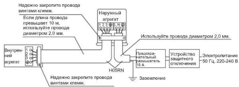
- For wiring, use a cable length enough to cover the entire distance with no connection. Do not use an extension cord. Do not put other loads on the power supply, use a dedicated power circuit. (Failure to do so may cause abnormal heat, electric shock or fire.)
- Use the specified types of wires for electrical connections between the indoor and outdoor units.
Firmly clamp the interconnecting wires so their terminals receive no external stresses. Incomplete connections or clamping may cause terminal overheating or fire. - After connecting interconnecting and supply wiring be sure to shape the cables so that they do not put undue force on the electrical covers or panels. Install covers over the wires. Incomplete cover installation may cause terminal overheating, electrical shock, or fire.
- If any refrigerant has leaked out during the installation work, ventilate the room. (The refrigerant produces a toxic gas if exposed to flames.)
After all installation is complete, check to make sure that no refrigerant is leaking out. (The refrigerant produces a toxic gas if exposed to flames.) - When installing or relocating the system, be sure to keep the refrigerant circuit free from substances other than the specified refrigerant (R410A), such as air.
(Any presence of air or other foreign substance in the refrigerant circuit causes an abnormal pressure rise or rupture, resulting in injury.) - During pump-down, stop the compressor before removing the refrigerant piping. If the compressor is still running and the stop valve is open during pump-down, air will be sucked in when the refrigerant piping is removed, causing abnormal pressure in the freezer cycle which will lead to breakage and even injury.
- During installation, attach the refrigerant piping securely before running the compressor. If the compressor is not attached and the stop valve is open during pump-down, air will be sucked in when the compressor is run, causing abnormal pressure in the freezer cycle which will lead to breakage and even injury.
- Be sure to establish an earth. Do not earth the unit to a utility pipe, arrester, or telephone earth. Incomplete earth may cause electrical shock, or fire. A high surge current from lightning or other sources may cause damage to the air conditioner.
- Be sure to install an earth leakage breaker. Failure to install an earth leakage breaker may result in electric shocks, or fire.

CAUTION
- Do not install the air conditioner in a place where there is danger of exposure to inflammable gas leakage. If the gas leaks and builds up around the unit, it may catch fire.
- Establish drain piping according to the instructions of this manual. Inadequate piping may cause flooding.
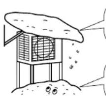
- Tighten the flare nut according to the specified method such as with a torque wrench. If the flare nut is tightened too hard, the flare nut may crack after a long time and cause refrigerant leakage.
| ·Make sure to provide for adequate measures in order to prevent that the outdoor unit be used as a shelter by small animals. Small animals making contact with electrical parts can cause malfunctions, smoke or fire. Please instruct the customer to keep the area around the unit clean. |
| ·This appliance is intended to be used by expert or trained users in shops, in light industry and on farms, or for commercial and household use by lay persons. |
| ·Sound pressure level is less than 70 dB(A). |
Accessories
Accessories supplied with the outdoor unit:
| (A) Installation Manual | 1 | (B) Drain plug (Heat pump-Models) It is on the bottom of the packing case. | 1 |
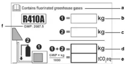
| (C) Refrigerant charge label Contains fluorinated greenhouse gases R410A ①= kg GWP: 2087.5 ②= kg ③+④= kg GWP + kg / 1000 = lCO2eq | |||
| (D) Multilingual fluorinated greenhouse gases label | 1 | ||
Precautions for Selecting the Location
1) Choose a place solid enough to bear the weight and vibration of the unit, where the operation noise will not be amplified.
2) Choose a location where the hot air discharged from the unit or the operation noise will not cause a nuisance to the neighbors of the user.
3) Avoid places near a bedroom and the like, so that the operation noise will cause no trouble.
4) There must be sufficient spaces for carrying the unit into and out of the site.
5) There must be sufficient space for air passage and no obstructions around the air inlet and the air outlet.
6) The site must be free from the possibility of flammable gas leakage in a nearby place.
7) Install units, power cords and inter-unit cables at least 3 meter away from television and radio sets. This is to prevent interference to images and sounds. (Noises may be heard even if they are more than 3 meter away depending on radio wave conditions.)
8) In coastal areas or other places with salty atmosphere of sulfate gas, corrosion may shorten the life of the air conditioner.
9) Since drain flows out of the outdoor unit, do not place under the unit anything which must be kept away from moisture.
NOTE
Cannot be installed hanging from ceiling or stacked.

CAUTION
When operating the air conditioner in a low outdoor ambient temperature, be sure to follow the instructions described below.
1) To prevent exposure to wind, install the outdoor unit with its suction side facing the wall.
2) Never install the outdoor unit at a site where the suction side may be exposed directly to wind.
3) To prevent exposure to wind, it is recommended to install a baffle plate on the air discharge side of the outdoor unit.
4) In heavy snowfall areas, select an installation site where the snow will not affect the unit.
- Construct a large canopy.
- Construct a pedestal.
Install the unit high enough off the ground to prevent burying in snow.
Outdoor Unit Installation Drawings
Installation Guidelines
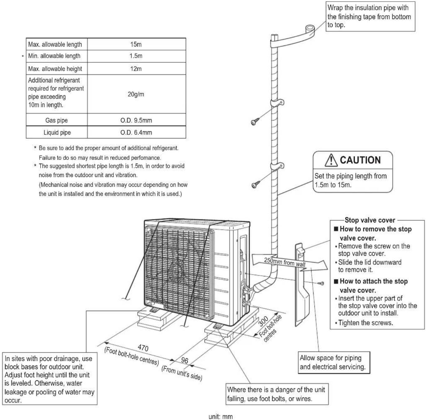
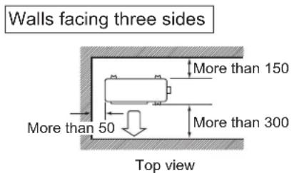
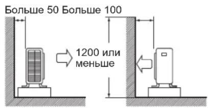
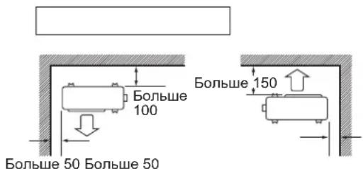
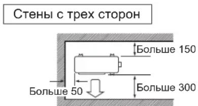
- Where a wall or other obstacle is in the path of outdoor unit's intake or exhaust airflow, follow the installation guidelines below.
- For any of the below installation patterns, the wall height on the exhaust side should be 1200mm or less.
Wall facing one side Walls facing two sides
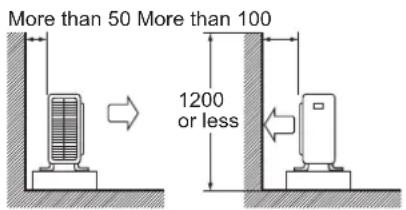
Side view
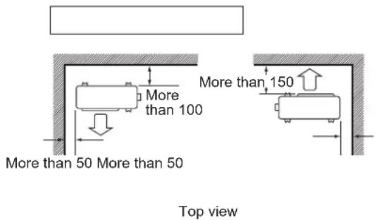
Unit: mm
Precautions on Installation
- Check the strength and level of the installation ground so that the unit will not cause any operating vibration or noise after installed.
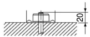
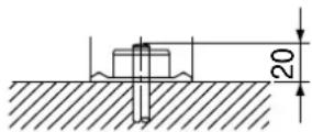
- In accordance with the foundation drawing, fix the unit securely by means of the foundation bolts. (Prepare four sets of M8 or M10 foundation bolts, nuts and washers each which are available on the market.)
- It is best to screw in the foundation bolts until their length are 20mm from the foundation surface.
Outdoor Unit Installation
1. Installing outdoor unit.
1) When installing the outdoor unit, refer to "Precautions for Selecting the Location" and the "Outdoor Unit Installation Drawings."
2) If drain work is necessary, follow the procedures below.
2. Drain work. (Heat pump-models.)
1) Use drain plug for drainage.
2) If the drain port is covered by a mounting base or floor surface, place additional foot bases of at least 30mm in height under the outdoor unit's feet.
3) In cold areas, do not use a drain hose with the outdoor unit. (Otherwise, drain water may freeze, impairing heating performance.)

Outdoor Unit Installation
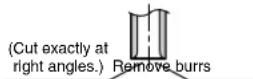
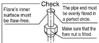
3. Flaring the pipe end.
1) Cut the pipe end with a pipe cutter.
2) Remove burrs with the cut surface facing downward so that the chips do not enter the pipe.
3) Put the flare nut on the pipe.
4) Flare the pipe.
5) Check that the flaring is properly made.
Flaring
| Flare tool for R410A | Conventional flare tool | |
| Clutch-type | Clutch-type (Rigid-type) | Wing-nut type (Imperial-type) |
| A 0-0.5mm | 1.0-1.5mm | 1.5-2.0mm |
WARNING
1) Do not use mineral oil on flared part.
2) Prevent mineral oil from getting into the system as this would reduce the lifetime of the units.
3) Never use piping which has been used for previous installations. Only use parts which are delivered with the unit.
4) Do never install a drier to this R410A unit in order to guarantee its lifetime.
5) The drying material may dissolve and damage the system.
6) Incomplete flaring may cause refrigerant gas leakage.
4. Refrigerant piping.
CAUTION
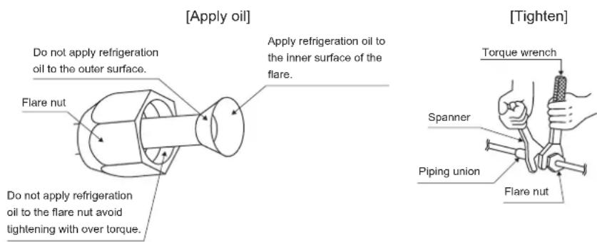
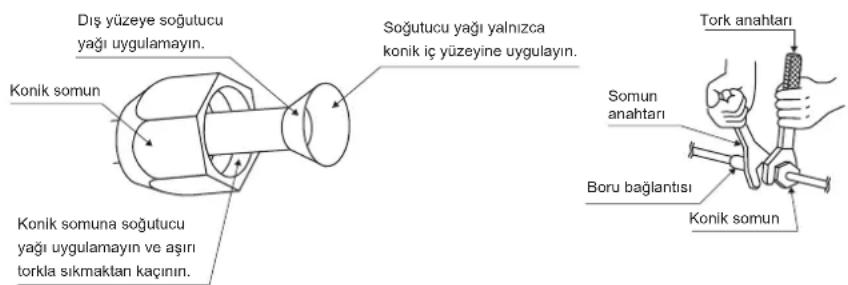
1) Use the flare nut fixed to the main unit. (To prevent cracking of the flare nut by aged deterioration.)
2) To prevent gas leakage, apply refrigeration oil only to the inner surface of the flare. (Use refrigeration oil for R410A.)
3) Use torque wrenches when tightening the flare nuts to prevent damage to the flare nuts and gas leakage.
Align the centres of both flares and tighten the flare nuts 3 or 4 turns by hand. Then tighten them fully with the torque wrenches.
| Flare nut tightening torque |
| Gas side Liquid side |
| 3/8 inch 1/4 inch |
| 32.7-39.9N·m 14.2-17.2N·m (333-407kgf·cm) (144-175kgf·cm) |
| Valve cap tightening torque | |
| Gas side Liquid side | |
| 3/8 inch 1/4 inch | |
| 21.6-27.4N·m 21(220-280kgf · cm) | .6-27.4N·m(220-280kgf · cm) |
| Service port cap | 10.8~14.7N·m |
| tightening torque | (110~150kgf·cm) |
Outdoor Unit Installation
5. Purging air and checking gas leakage.
- When piping work is completed, it is necessary to purge the air and check for gas leakage.

WARNING
1) Do not mix any substance other than the specified refrigerant (R410A) into the refrigeration cycle.
2) When refrigerant gas leaks occur, ventilate the room as soon and as much as possible.
3) R410A, as well as other refrigerants, should always be recovered and never be released directly into the environment.
4) Use a vacuum pump for R410A exclusively. Using the same vacuum pump for different refrigerants may damage the vacuum pump or the unit.
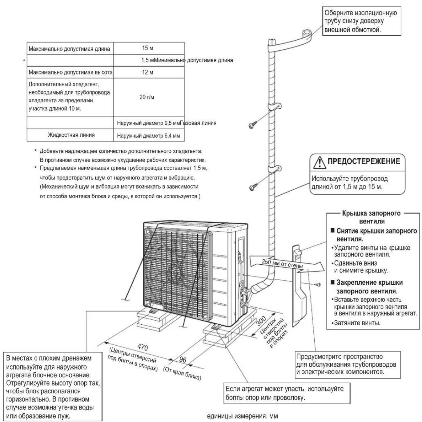
- If using additional refrigerant, perform air purging from the refrigerant pipes and indoor unit using a vacuum pump, then charge additional refrigerant.
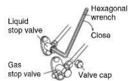
- Use a hexagonal wrench (4mm) to operate the stop valve rod.
- All refrigerant pipe joints should be tightened with a torque wrench at the specified tightening torque.
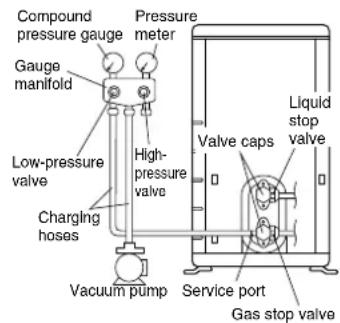
1) Connect projection side of charging hose (which comes from gauge manifold) to gas stop valve's service port.

2) Fully open gauge manifold's low-pressure valve (Lo) and completely close its high-pressure valve (Hi). (High-pressure valve subsequently requires no operation.)

3) Do vacuum pumping and make sure that the compound pressure gauge reads -0.1MPa(-76cmHg)^*1

4) Close gauge manifold's low-pressure valve (Lo) and stop vacuum pump. (Keep this state for a few minutes to make sure that the compound pressure gauge pointer does not swing back.)*2.

5) Remove caps from liquid stop valve and gas stop valve.

6) Turn the liquid stop valve's rod 90 degrees counterclockwise with a hexagonal wrench to open valve. Close it after 5 seconds, and check for gas leakage. Using soapy water, check for gas leakage from indoor unit's flare and outdoor unit's flare and valve rods. After the check is complete, wipe all soapy water off.

7) Disconnect charging hose from gas stop valve's service port, then fully open liquid and gas stop valves. (Do not attempt to turn valve rod beyond its stop.)

8) Tighten valve caps and service port caps for the liquid and gas stop valves with a torque wrench at the specified torques.
1. Pipe length vs. vacuum pump run time.
Pipe length Up to 15 metres
Run time Not less than 10 min.
2. If the compound pressure gauge pointer swings back, refrigerant may have water content or a loose pipe joint may exist. Check all pipe joints and retighten nuts as needed, then repeat steps 2) through 4).
Outdoor Unit Installation
6. Refilling the refrigerant.
Check the type of refrigerant to be used on the machine nameplate.
Precautions when adding R410A
Fill from the liquid pipe in liquid form.
It is a mixed refrigerant, so adding it in gas form may cause the refrigerant composition to change, preventing normal operation.
1) Before filling, check whether the cylinder has a siphon attached or not. (It should have something like "liquid filling siphon attached" displayed on it.)
Filling a cylinder with an attached siphon
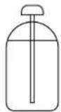
Stand the cylinder upright when filling.
There is a siphon pipe inside, so the cylinder need not be upside-down to fill with liquid.
Filling other cylinders
Turn the cylinder upside-down when filling.
- Be sure to use the R410A tools to ensure pressure and to prevent foreign objects entering.
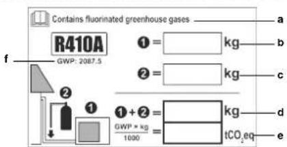
To fix the fluorinated greenhouse gases label
Fill in the label as shown in the illustration.
a If a multilingual fluorinated greenhouse gases label is delivered with the unit (see accessories), peel off the applicable language and stick it on top of a.
b Factory refrigerant charge: see unit name plate
c Additional refrigerant amount charged
d Total refrigerant charge
e Greenhouse gas emissions of the total refrigerant charge expressed as tonnes CO_2 equivalent
f GWP = Global warming potential
#
NOTICE
In Europe, the greenhouse gas emissions of the total refrigerant charge in the system (expressed as tonnes CO_2 -equivalent) is used to determine the maintenance intervals. Follow the applicable legislation.
Formula to calculate the greenhouse gas emissions: GWP value of the refrigerant × Total refrigerant charge [in kg] / 1000
Use the GWP value mentioned on the greenhouse gases label. This GWP value is based on the 4th IPCC Assessment Report. The GWP value mentioned in the manual might be outdated (i.e., based on the 3rd IPCC Assessment Report).
2 Fix the label on the unit according to the instructions in the manual.
7. Refrigerant piping work.
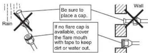
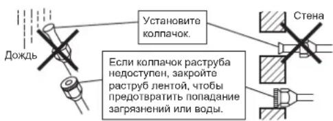
7-1 Cautions on pipe handling.
1) Protect the open end of the pipe against dust and moisture.
2) All pipe bends should be as gentle as possible. Use a pipe bender for bending.
7-2 Selection of copper and heat insulation materials.
When using commercial copper pipes and fittings, observe the following:
1) Insulation material: Polyethylene foam Heat transfer rate: 0.041 to 0.052W / mK (0.035 to 0.045kcal/(mh ·^) Refrigerant gas pipe's surface temperature reaches 110^ max. Choose heat insulation materials that will withstand this temperature.
2) Be sure to insulate both the gas and liquid piping and to provide insulation dimensions as below.
| Gas side Liquid | side | Gas pipe thermal insulation | Liquid pipe thermal insulation |
| O.D. 9.5mm O.D. | 6.4mm I.D. 12-15mm | I.D. 8-10mm | |
| Minimum bend radius Thickness 10mm Min. | |||
| 30mm or more | |||
| Thickness 0.8mm (C1220T-O) | |||
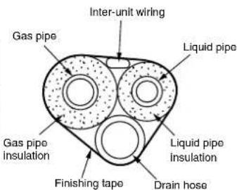
3) Use separate thermal insulation for gas and liquid refrigerant pipes.
Pump Down Operation
In order to protect the environment, be sure to pump down when relocating or disposing of the unit.
1) Remove the valve cap from liquid stop valve and gas stop valve.
2) Carry out forced cooling operation.
3) After five to ten minutes, close the liquid stop valve with a hexagonal wrench.
4) After two to three minutes, close the gas stop valve and stop forced cooling operation.
How to force cooling operation mode
Using the indoor unit operation/stop button
Press the indoor unit operation/stop button for at least five seconds. (Operation will start.)
- Forced cooling operation will stop automatically after around 15 minutes.
To force a test run to stop, press the indoor unit operation/stop button.
Using the main unit's remote controller
1) Press the "operation/stop" button. (Operation will start.)
2) Press the temperature button and the "operation select" button at the same time.
3) Press the "operation select" button twice.
will be displayed and the unit will enter test run mode.)
4) Press the "operation select" button to return the operation mode to cooling.
- Test run mode will stop automatically after around 30 minutes. To force a test run to stop, press the operation/stop button.

CAUTION
1) When pressing the switch, do not touch the terminal block. It has a high voltage, so doing so may cause electric shock.
2) After closing the liquid stop valve, close the gas stop valve within three minutes, then stop the forced operation.
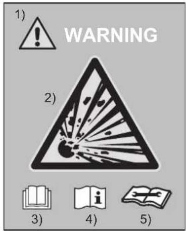
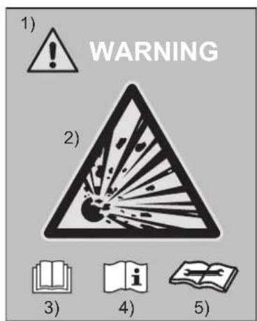
WARNING
The unit is accompanied with the label below.
Please read the following instructions carefully.

- When the refrigeration circuit has a leak, do not execute pump down with the compressor.
Use recovery system into separate cylinder - Warning, explosive hazard exists when executing pump down.
- Pump down with compressor can lead to self-combustion due to air entering during pump
Used symbols:
Warning sign (ISO 7010-W001)
2 Warning, Explosive material (ISO 7010-W002)
3 Read Operator's manual (ISO 7000 - 0790)
Operator's manual; operating instructions (ISO 7000 - 1641)
5 Service indicator; read technical manual (ISO 7000 - 1659)
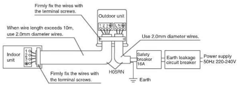
Wiring

WARNING
1) Do not use tapped wires, stranded wires, extension cords, or starburst connections, as they may cause overheating, electrical shock, or fire.
2) Do not use locally purchased electrical parts inside the product. (Do not branch the power for the drain pump, etc., from the terminal block.) Doing so may cause electric shock or fire.
3) Be sure to install an earth leakage breaker. (One that can handle higher harmonics.) (This unit uses an inverter, which means that it must be used an earth leakage breaker capable handling harmonics in order to prevent malfunctioning of the earth leakage breaker itself.)
4) Use an all-pole disconnection type breaker with at least 3mm between the contact point gaps.
5) Do not connect the power wire to the indoor unit. Doing so may cause electric shock or fire.
- Do not turn ON the power supply until all work is completed.
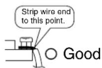
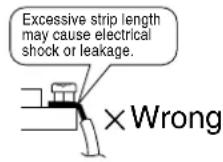
1) Strip the insulation from the wire (20mm).
2) Connect the connecting wires between the indoor and outdoor units so that the terminal numbers match. Tighten the terminal screws securely. We recommend a flathead screwdriver be used to tighten the screws. The screws are packed with the terminal board.
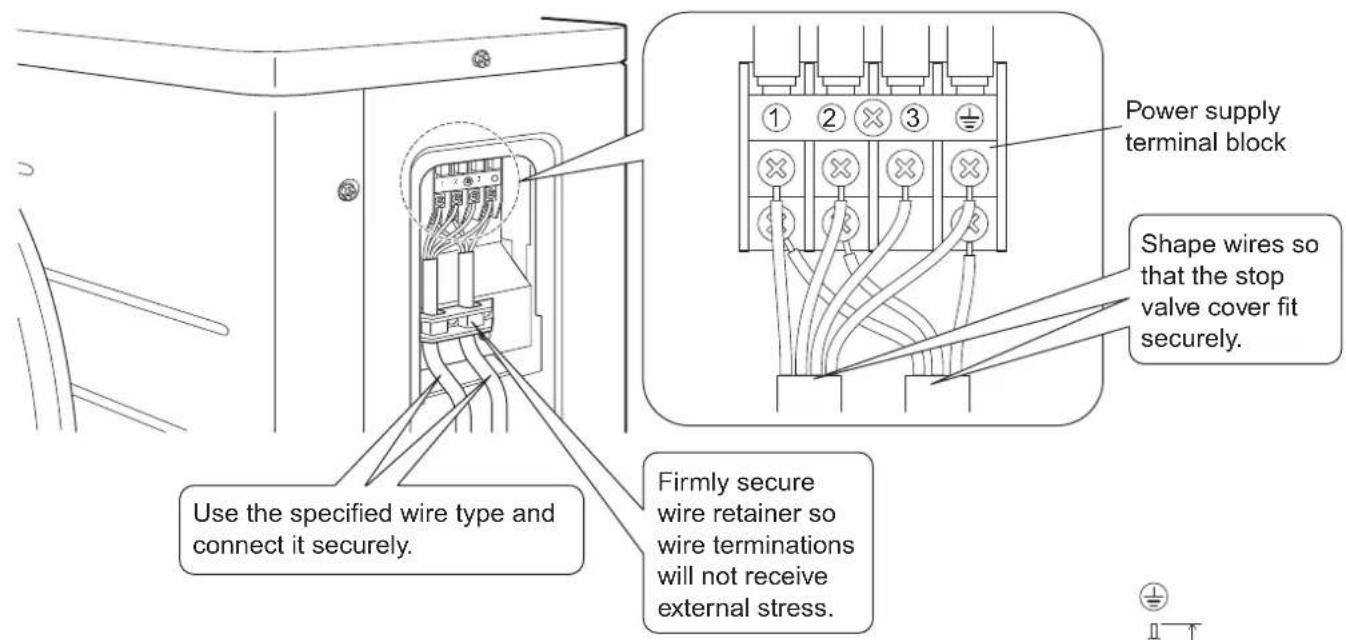
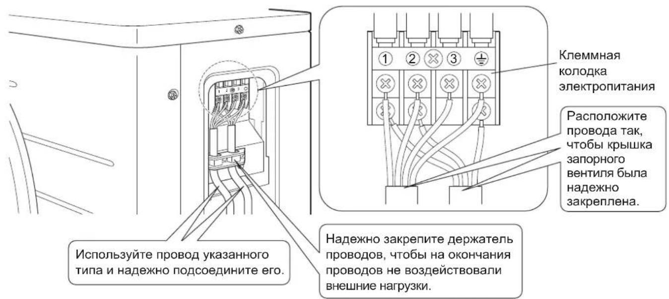
Observe the notes mentioned below when wiring to the power supply terminal board.
Precautions to be taken for power supply wiring.
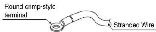
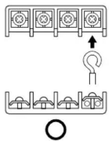
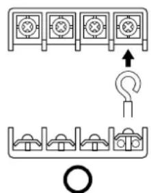
Use a round crimp-style terminal for connection to the power supply terminal board. In case it cannot be used due to unavoidable reasons, be sure to observe the following instruction.
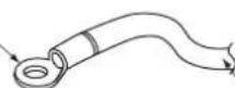
Place the round crimp-style terminals on the wires up to the covered part and secure in place.
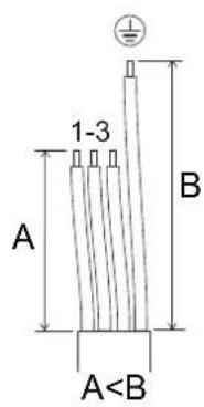
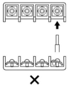
When connecting the connecting wires to the terminal board using a single core wire, be sure to perform curling. Problems with the work may cause heat and fires.
Stripping wire at terminal block
3) Pull the wire and make sure that it does not disconnect. Then fix the wire in place with a wire stop.
Wiring
Wiring diagram
:Terminal strip :Field wiring
:
:Connector:Terminal

:Connection
BLK:Black ORG:Orange
BLU:Blue RED:Red
BRN: Brown WHT: White
GRN:Green
YLW
:Yellow
Notes : Refer to the nameplate of the unit for power requirements.
:OUTDOOR
Outdoor
: CONDenser
Condenser
: DISCHARGE
Discharge
Wiring diagram parts table
C1,C2,C400,C405.. Capacitor
V1R. Diode bridge
E1, E2, HL1, HN1,
S, HR1, HR2. Connection
FU2, FU3 ...Fuse
IPM1, IPM2 Intelligent power module
L. Live
L1R. Reactor
M1C. Compressor motor
M1F. Fan motor
K30R, K10R, MR4 Magnetic relay
N. Neutral
A1P. Printed circuit board
PS .Power supply
Q1M Overload protector
R1T, R2T, R3T, PTC ....Thermistor
S20,S30,S40,
S71,S80,S90.........Connector
F1S. Surge arrester
V2,V3. Varistor
X1M. Terminal strip
Y1E Electronic expansion valve coil
Y1S. Four way valve coil
Z1C,Z2C,Z3C..Ferrite core
Protective earth
Earth
Test Run and Final Check
1. Trial operation and testing.
1-1 Measure the supply voltage and make sure that it falls in the specified range.
1-2 Trial operation should be carried out in either cooling or heating mode.
For heat pump
- In cooling mode, select the lowest programmable temperature; in heating mode, select the highest programmable temperature.
1) Trial operation may be disabled in either mode depending on the room temperature.
2) After trial operation is complete, set the temperature to a normal level (26°C to 28°C in cooling mode, 20°C to 24°C in heating mode).
3) For protection, the system disables restart operation for 3 minutes after it is turned off.
For cooling only
1) Trial operation in cooling mode may be disabled depending on the room temperature.
2) After trial operation is complete, set the temperature to a normal level (26^ to 28^)
3) For protection, the unit disables restart operation for 3 minutes after it is turned off.
1-3 Carry out the test operation in accordance with the operation manual to ensure that all functions and parts, such as louver movement, are working properly.
- The air conditioner requires a small amount of power in its standby mode. If the system is not to be used for some time after installation, shut off the circuit breaker to eliminate unnecessary power consumption.
- If the circuit breaker trips to shut off the power to the air conditioner, the system will restore the original operation mode when the circuit breaker is opened again.
2. Test items.
| Test items | Symptom (diagnostic display on RC) | Check |
| Indoor and outdoor units are installed properly on solid bases. Fall, vibration, | noise | |
| No refrigerant gas leaks. | Incomplete cooling/heating function | |
| Refrigerant gas and liquid pipes and indoor drain hose extension are thermally insulated. | Water leakage | |
| Draining line is properly installed. Water leakage | ||
| System is properly earthed. Electrical leakage | ||
| The specified wires are used for interconnecting wire connections. | Inoperative or burn damage | |
| Indoor or outdoor unit's air intake or exhaust has clear path of air. Stop valves are opened. | Incomplete cooling/heating function | |
| Indoor unit properly receives remote control commands. Inoperative |
Sicherheitshinweise
K30R, K10R, MR4 ....... Magnetrelais
R1T, R2T, R3T, PTC ...Thermistance
S20,S30,S40,
S71,S80,S90....Connecteur
F1S .Parasurtenseur
V2, V3.......Varistance
X1M. .Barrette de raccordement
R1T, R2T, R3T, PTC ....Thermistor
S20,S30,S40,
S71,S80,S90.........Connector
F1S .Spanningsbeveiling
V2, V3.......Varistor
R1T, R2T, R3T, PTC ....Termistor
S20,S30,S40,
S71,S80,S90.....Conector
S, HR1, HR2. Concessione
FU2, FU3 Fusibile
K30R, K10R, MR4 ... Mayvntiko pελέ
N. Oudéτερο
A1P. ..IaKaTe Ta TUTUeVou KukuWatoC (PCB)
PS .
Q1M .Pooataia aTou TEPPOPTOW
R1T, R2T, R3T, PTC ....Aioθηηρας
S20,S30,S40,
S71,S80,S90. Akpoδεκτης
F1S ...iatae n pooaiaac aio utepaon
V2, V3........Bapiotop
X1M. ..Kt aKpOeKrWv
Y1E. ..Iyio nAektpovikns Bavae EKToVwOns
Y1S Tcogepic tpoTnVio ngs baaii8ac
Z1C,Z2C,Z3C.. Fluprivac eppin
PpOoTateutikyeiwn
+
HnkOrda He nbItaTaeTcB.
- Pocne 3aBepueHnMa MOnTaKa NcBbTaIe 6Nok, YTo6bI npOBepuTb Ha npEpmet OwU6oK MoTtaka.
PonHCTpyKTHpyIte nIb3OBaTeTnHaIeKaUm O6pa3OM OTHOcHTbHO IcNoJIb3OBaHn N OUnCTKn 6Noka corlaCHO pyKOBOCTBy NO EKcnJyatau.
OpunHaonom pykoBocCTBa YBnEeTc TaekT Ha aHrnnckom 3bike. TeKCT Ha npynx 3bikax YBnEeTc nepeboDom copnHa n a.
| ΔРЕДУПЕХДЕНЕ |
| ·МоNTаж Должени Вьлеловпддгер ппддгог сдсцалпост. Helenpавильна установka может рпвес'tк К рoteханям BОд, поаржени Злелотричесим TOKOM ппь ВОЗгоранio. |
| ·Установite КОндциноер сordлacno ИСТРУКИМС, садржшиимсь в STOM рукововдбve. Helenpавильна установka может рпвес'tк К рoteханям BОд, поаржени Злелотричесим TOKOM ппь ВОЗгоранio. |
| ·ИспolyзуITE ВХODДУЗЕ В KOMЛLEKT NOCTВКИ ппь YKAZAHНБDEДАД ПМОТЖА. Испolyзованые дуггдддгел может рпьс'tк К паденio 6bloka, утукам BОд, поаржени Zлелотричесим TOKOM ппь ВОЗгоранio. |
| ·Установыпддддддддддддддддддддддддддддддддддддддддддддддддддддддддддддддддддддддддддддддддддддддддддддддддддддd He отеваяю Стравогин� мостованые ппь He npвges'tк могу ТраВмam BСлуаe паденia 6bloka C OSHOBANIA. |
| ·Злелот priestхнистпсь работы Должны пrobovotьсь в COOTBETCTBnC pPyKOBODCTBOM NO MONTAZKY, a TAKGE NauhoHbHbIMI npabivlAmNo 3лелотроповodкe и раKFTHPCEKIM N epokemHdaцям. HedocTAtOCHa MOnuHcstb I HezABpeHsHbte 3лелOTPOKEXHUNe 3лелOTPOKHECCKne pabotb MOrT bBy3BbTb PpaXeHne 3лелOTPCHECKM TOKOM ппь WOZROPAHNE. |
| ·ДЯп STANHЯ СYNTEМБI HeobxOДIMA OTdeьнг�ець снIOBOr O3лелOTPONITAHIN. He DonyUckaetcя PodknIOHу K3лелOTPCHUCKO K 3лелOTPCHUCKOцEN, KOTOPAR UYE HHTpy NOTBTEEN. ·Дяп рpoвддддддддддддддддддддддддддддддддддддддддддддддддддддддддддддддддддддддддддддддддддддддддддддддддддд HedecHTo HeobxOДIMo NcPONL3OBATb Ka6elb DOCTaTOChHДПINHbI, YTObI OXBaTtB BCE paCCTOHRHne 6e3 Испolyбане уддддддддддддддддддддддддддддддддддддддддддддддддддддддддд HedocTAtOCHa MOnuHcstb I HezABpeHsHbte 3лелOTPOKHECCKne pabotb MOrT bBy3BbTb PpaXeHne 3лелOTPCHUCKM TOKOM ппь WOZROpAHNE. |
| ·ДЯп STANHЯ СYNTEМБI HeobxOДIMA OTdeьнг�ець снIOBOr O3лелOTPONITAHIN. He DonyUckaetcя HabOBOr O3лелOTPCHUCKO K 3лелOTPCHUCKOцEN, KOTOPAR UYE HHTpy NOTBpy, NaOeHnO NcPONL3yIte PpoBODa YkazAHNbIX TINOB. HedecHTo 3akmte coeDINHITbIe ПОвODа, YTObI Ha IX KIeMMbI He BOZdIeCTBOvAln BHeUHIne HarguzK. Ecln рpoвдддддддддддддддддд HedocTAtOCHa MOnuHcstb I InI 3akzAteb, Bo3MOeHn PpeTReB KIeMMI INI NOXAP. ·Посе рoвддддддддддддддддддддддддддддддд HedocTAtOCHa MOnuHcstb I InI 3akzAteb, Bo3MOeHn PpeTReB KIeMMI INI NOXAP. ·Посе рoвдддддддддддддддддддд HedocTAtOCHa MOnuHcstb I InI 3akzAteb, Bo3MOeHn PpeTReB KIeMMI INI NOXAP. ·Посе рoвддддддддд HedocTAtOCHa MOnuHcstb I InI 3akzAteb, Bo3MOeHn PpeTReB KIeMMI INI NOXAP. ·Посе рoвдддд HedocTAtOCHa MOnuHcstb I InI 3akzAteb, Bo3MOeHn PpeTReB KIeMMI INI NOXAP. ·Посе рoвдд HedocTAtOCHa MOnuHcstb I InI 3akzAteb, Bo3MOeHn PpeTReB KIeMMI INI NOXAP. ·Посе рoвд HedocTAtOCHa MOnuHcstb I InI 3akzAteb, Bo3MOeHn PpeTReB KIeMMI INI NOXAP. ·Посе рoв HedocTAtOCHa MOnuHcstb I InI 3akzAteb, Bo3MOeHn PpeTReB KIeMMI INI NOXAP. ·Посе рoв HedocTAtOCHa MOnuHcstb I InI 3akzAteb, Bo3MOeHn PpeTReB KIeMMI NIOLOH ·Посе рoв HedocTAtOCHa MOnuHcstb I InI 3akzAteb, Bo3MOeHn PpeTReB KIeMMI NIOLOH ·Посе рoв HedocTAtOCHa MOnuHcstb I InI 3akzAteb, Bo3MOeHn PpeTRe HedocTAtOCHa MOnuHcstb I InI 3akzAteb, Bo3MOeHn PpeTRe HedocTAtOCHa MOnuHcstb I InI 3akzAteb, Bo3MOeHn PpeTRe HedocTAtOCHa MOnuHcstb I InI 3akzAteB HedocTAtOCHa MOnuHcstb I InI 3akzAteB HedocTAtOCHa MOnuHcstb I InI 3akzAteB HedocTAtOCHa MOnuHcstb I InI 3akzAteB HedocTAtOCHa MOnuHcstb I InI 3AKPENITe Tp6OBPONOB XlaDAreHtA B03dYx БуSpecуг HedocTAtOCHa MOnuHcstb I InI 3AKPENITe Tp6OBPONOB XlaDAreHtA HedocTAtOCHa MOnuHcstb I InI 3AKPENITe Tp6OBPONOB XlaDAreHtA HedocTAtOCHa MOnuHcstb I InI 3AKPENITe Tp6OBPONOB XlaDAreHtA HedocTAtOCHa MOnuHcstb I InI13K HedocTAtOCHa MOnuHcstb I InI 3AKPENITe Tp6OBPONOB XlaDAreHtA HedocTAtOCHa MOnuHcstb I InI 3AKPENITe Tp6OBPONOB XlaDAreHtA HedocTAtOCHa MOnuHcstb I InI I3K HedocTAtOCHa MOnuHcstb I InI 3AKPENITe Tp6OBPONOB XlaDAreHtA HedocTAtOCHa MOnuHcstb I InI 3AKPENITe Tp6OBPONOB XlaDAreHtA HedocTAtOCHa MOnuHcstb IInI 3AKPENITe Tp6OBPONOB XlaDAreHtA HedocTAtOCHa MOnuHcstb I InI 3AKPENITe Tp6OBPONOB XlaDAreHtA HedocTAtOCHa MOnuHcstb I InI 3AKPENITe Tp6OBPONOB XlaDAre HedocTAtOCHa MOnuHcstb I InI 3AKPENITe Tp6OBPONOB XlaDAre HedocTAtOCHa MOnuHcstb I InI 3AKPENITe Tp6OBPONOB XlaDAre HedocTAtOCHa MOnuHcstb I InI 3AKPENITE Tp6OBPONOB XlaDAre HedocTAtOCHa MOnuHcstb I InI 3AKPENITe Tp6OBPONOB XlaDAre HedocTAtOCHa MOnuHcstb I InI 3AKPENITe Tp6OBPONOB XlaDAre HedocTAtOCHa MOnuHcSTbIg Tp6OBPONOB XlaDAre HedocTAtOCHa MOnuHcSTbIg Tp6OBPONOB XlaDAre HedocTAtOCHa MOnuHcSTbIg Tp6OBPONOB XlaDAre HedocTAtOCHa MOnuHcSTbIg Tp6OBPONOB XlaDAre TуSpecуг HedocTAtOCHa MOnuHcSTbIg Tp6OBPONOB XlaDAre HedocTAtOCHa MOnuHcSTbIg Tp6OBPONOB XlaDAre HedocTAtOCHa MOnuHcSTbIg Tp6OBPONOB XlaDAre HedocTAtOCHa MOnuHa Tp6OBPONOB XlaDAre HedocTAtOCHa MOnuHa Tp6OBPONOB XlaDAre HedocTAtOCHa MOnuHa Tp6OBPONOB XlaDAre HedocTAtOCHa MOnuHa Tp6OBPONOB XlaDAre HedocTAtOCHa MOnuHa Tp6 OBPONOB XlaDAre HedocTAtOCHa MOnuHa Tp6OBPONOB XlaDAre HedocTAtOCHa MOnuHa Tp6OBPONOB XlaDAre HedocTAtOCHa MOnuHa Tp6OBPONOB XlaDAre HedocTAtOCHa MOnuHa Tp6OBPONOB HedocTAtOCHa MOnuHa Tp6OBPONOB XlaDAre HedocTAtOCHa MOnuHa Tp6OBPONOB XlaDAre HedocTAtOCHa MOnuHa Tp6OBPONOB XlaDAre HedocTAtOCHa MOnuHa Tp6OBPONOB XlaDAre HedOCTAtOCHa MOnuHa Tp6OBPONOB XlaDAre HedOCTAtOCHa MOnuHa Tp6OBPONOB XlaDAre HedOCTAtOCHa MOnuHa Tp6OBPONOB XlaDAre HedOCTAtOCHa MOnuHa Tp6OBPONOB XlaDAre HedOCTAtOchMOnuHa Tp6OBPONOB XlaDAre HedOCTAtOCHa MOnuHa Tp6OBPONOB XlaDAre HedOCTAtOCHa MOnuHa Tp6OBPONOB XlaDAre HedOCTAtOCHa MOnuHa Tp6OBPONOB XlaDAre HedOCTAtOCHa MOnuHa HedOCTAtOCHa MOnuHa Tp6OBPONOB XlaDAre HedOCTAtOCHa MOnuHa Tp6OBPONOB XlaDAre HedOCTAtOCHa MOnuHa Tp6OBPONOB XlaDAre HedOCTAtOCHa MOnuHa Tp6OBPONOB XlaDAre HedocTAtOCHa MOnuHa Tp6OBPONOB XlaDAre HedOCTAtOCHa MOnuHa Tp6OBPONOB XlaDAre HedOCTAtOCHa MOnuHa Tp6OBPONOB XlaDAre HedOCTAtOchMOnuHa Tp6OBPONOB XlaDAre HedOCTAtOCHA MOnuHa Tp6OBPONOB XlaDAre HedOCTAtOCHa MOnuHa Tp6OBPONOB XlaDAre HedOCTAtOCHa MOnuHa Tp6OBPONOB XlaDAre HedOCTAtOCHa MOnuHa Tp6OBPONOB XlaDAre HedOCTAtOCHa MOnuHc Tp6OBPONOB XlaDAre HedOCTAtOCHa MOnuHa Tp6OBPONOB XlaDAre HedOCTAtOCHa MOnuHa Tp6OBPONOB XlaDAre HedOCTAtOCHa MOnuHa Tp6OBPONOB XlaDAre HedOCTAtOCHa MOnuHa Tp6 OBPONOB XlaDAre HedOCTAtOCHa MOnuHa Tp6OBPONOB XlaDAre HedOCTAtOCHa MOnuHa Tp6OBPONOB XlaDAre HedOCTAtOCHa MOnuHa Tp6OBPONOB XlaDAre HedOCTAtOCHa MOnuHa Tp6OBPONOB HedOCTAtOCHa MOnuHa Tp6OBPONOB XlaDAre HedOCTAtOCHa MOnuHa Tp6OBPONOB XlaDAre HedOCTAtOCHa MOnuHa Tp6OBPONOB XlaDAre HedOCTAtOCHa MOnuHa Tp6OBPONOB XlaDAre Hed OC TCHB HedocTAtOCHa MOnuHa Tp6OBPONOB XlaDAre HedocTAtOCHa MOnuHa Tp6OBPONOB XlaDAre HedocTAtOCHa MOnuHa Tp6OBPONOB XlaDAre HedocTAtOCHa MOnuHa Tp6OBPONOB XlaDAre HedocsTCHB HedocTAtOCHa MOnuHa Tp6OBPONOB XlaDAre HedocTAtOCHa MOnuHa Tp6OBPONOB XlaDAre HedocTAtOCHa MOnuHa Tp6OBPONOB XlaDAre HedocTAtOCHa MOnuHa Tp6OBPONOB XlaDAre HG HedocTAtOCHa MOnuHa Tp6OBPONOB XlaDAre HedocTAtOCHa MOnuHa Tp6OBPONOB XlaDAre HedocTAtOCHa MOnuHa Tp6OBPONOB XlaDAre HedocTAtOCHa MOnuHa Tp6OBPONOB XlaDAre HedoxTCHB HedocTAtOCHa MOnuHa Tp6OBPONOB XlaDAre HedocTAtOCHa MOnuHa Tp6OBPONOB XlaDAre HedocTAtOCHa MOnuHa Tp6OBPONOB XlaDAre HedocTAtOCHa MOnuHa Tp6OBPONOB XlaDAre |
| ПЕДОCTEPEЖЕHICE |
| • He yctanablnbaiTe KOHdiuioHeB B TAKOM MecTe, B KOTOpom cyuceCTByET ONaCHocTb yTeckn orHeonachoro rata. В с沌аe yteckn i skonlpeneHra3a BOKpyr 6boka Bo3MOxeh noxap. |
| • UctahOBITE Дрehaxhblу TrpyobnpoBOD corgaLacHO INHCTpyKzmaRm, COdepkauzimC8 B 3Tom rykoBODCTBE. He otbeauoIy TrpeboaHnM TrpyobnpoBOD MOXet npuBeCTn K pa3NHyB VBoIy. |
| • 3aTaNHTe HakndHyO raKyu HndlexaUzIM o6pa30m, Hapnimep DInHAMOMETPruYeCKM K1IOYOM. Ecni HakndHra yaka 3aTaNHTa CnIIKOM CnIbHo, Chee3 HeKOTOpoe BpeM OHa MOxet TpeCHyT, YTo npuBeJeT K yTeKe XnaDaReHtA. |
| • 6b4aTeNbH No pRIMNTe aDeKBaTHbIe MEPb NO HeDOnyuSeHIO NOnaDaHnB H hapyKbH aRperaT MeKkNx XNBOTbIX. Ppi KOnTaTe MeKnIX JxBcOTbIX C DeTalAm NiD HapryxeHem Bo3MOxHb C6bN B pa6Ote 6boka, ZdaBImHeNne NiN Bo3rOpaHne. PpOHNCTpyKtpuyTe 3aKa3UHcA O TOM, YTo npocTpaHCTBO BOKpyr arperaT Heo6XoDIMO CODepKazb T B YChTOTE. |
| • Данhoe yctpoJCTBO MOxET NCNoB3OBaTbC R CNeUaJIncTAmN NiN O6byeHbIM NOnb3OBaTeJMaM N Mara3Hax, Ha ppeDpnpaTnX JleKoN IpnMbIshJeHHOCtN, Ha φepmax, Ni6O HeCneUaJIncTAmN DnI KOMMepeCkNix N 6bITOBbIX Huxd. |
| • UpoBeHb 3ByKOBOrO daBLeHnI: MeHee 70 d5(A). |
Приноадлесхоста
PnHaJneXHocTn, NOCTaBJIeMbIe C HApYKbIM arperaTOM:
He donyckaetcnoDBeWNBaTb arperaTbHa noToIke nIy ycTaHaBnBaTb Ix dpyr Ha npya.

ПЕДОCTEPEЖЕНЕ
Pn3KcNlNyatauN KOHdUHHepa B yCNoBnX Hn3KoT Tempeatypb OkpykaIoUeBO3dyxaO6aTeNbHO CJeDyIe HxKePnBeDeHHbIM NHCTpykUaM.
1)Bo n36eKaHHe DeiCTBnBa Betpa yctaHaBnBaIte HapyKbI arperat CTopoHOB BCacbIBaHnK CTEHe.
2) He yctaHaBnBaIte HapyKbI arperaT B MecTe, Ie CTopoHa BCacbBaHm MOKeT 6bITb NODBeprHyTa HENOCpeiCTBeHHOMy DeiCTBIO Betpa.
3)ДязauNTbI OT Betpa peKOMeHdyETcra 3akpbITb CTOpOHy Bblnycka BO3duxHa HApYKHOrO arperaTa 3auNTbIM 3kpaHOM.
4) B pernohax, Ie obuHNO bInaJaT MHorO chera, arperat Heo6xOIMO yCTaHaBnBaTb B TAKOM MeCTe, UTo6bI CHER He npenrTcBOBAn erO HopMaBHO pa6ote.
YCTaHOBtBe 6nK Ha DocTaOuHOB
BbICote HAD NOBepXHOCTbIO EMNI,
4TObI pTeoTbPAiTb 3acbinaHHe
CHAECFOM.
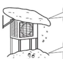
CdelaIte6oIbwoKo3bipeK.
CdetaIe noCTaBky.
Mонтajхьий черпж НapyжHoro arperata
ПразвILA мOLTажа
- Ecnn Ha nytn Bnyska Bo3dyxa nn NoToKa BbIXoJaIero Bo3dyxa HApyXHoro arperata eCTb CTeHa nn npenrTCTBne, BblIOJIHnTe CnElyOUIne DeIcTBnI NO MOHTaKy.
-ДяВСЕОПСАнБИХ HNKe CXeM yCTaHOBKn BbICOTa CTeHb Ha CTopoHc BbInycka ДОЛЖHa 6bITb He 6OJee 1200 MM.
CTeHa C OndHoi CTOpOHbI CTeHbIC DByx CTOpOH
Budc6oky
Budcpexy
BudcBepxu
EINHINCIbI N3MepeHHa:MM
Мерсы пре dioctopoxkHOCTn ри установke
- PpOBeBpTe npOuHocTb n rOp3oHTaJIbHocTb nlouaKn IJIy yCTaHOBKn, TAK YTObI aRperat nocne yCTaHOBKn He Bbl3bIBan Bn6paun nn Wyma npn pa6ote.
- Cornacho Фундам ent homу четху hydexho 3akpenite arperat Фундам ent hblm60lram. (Iodrotobte yetbipe kOmnekta фундам ent hblx 60ltoB M8 nln M10, raeки shaig, npno6peTaembix no Mecty yctahOBkn.)
- ONTIMaJIbHO 6yIeT BBNHTnB ΦyHdAmEHTHbIe 6oNTbl, OCTaBvB 20 MM HAD NOBepxHOcTBIO ΦyHdAmeHTa.
MoHTaX HapyxHoro arperata
1. Mohtax HapyxHoro arperata.
1)Пи монтaxes hapxHoro arperata cm. pa3dJIb "IpeoctepxeHn OTHocHTeHbHO Bb6opa MeCTa MoHTaxa" n "Mонтхьй чeTeX hapxHoro arperata".
2) Ecn Tpe6yIoc dapehakHbIe pa6oTbI, BblOnHInTe npedcTabneHHyo Hnke ppoceDpy.
3aipabKa n3 dpynx 6aJIIOHOB
IpepeBepHnTe 6aannoh npn 3anpaBke.
- IcnoIb3yIte INCTpyMeHTbl dIra R410A, yTo6bl obecneHTb daBHeHne n IpeDoTbpaTb npOHKnHOBeHne nOctOpOHnx npEdMeTOB.
HaKneKa 3TNKeTKn C HΦopMaueNe O ΦTopnpoBaHHbIX Ra3ax, cnocO6CTByUOux CO3daHnnapHKOBOrO 3ΦΦeKta
3anonHnTe 3TNKeTky, KaK nokaHa Ho npCyHke.
a EcIn B KOMnEeT NOCTaBKn 6JIOKA BXoNT 3TNKeTka O HAIINH BbIbBAOuNX NAPHNKOBBI 3ΦΦeKT ΦTOPcOePkauxra3OB Ha HeCKoNbKnx 3bIkax (CM. pINHaJIeXHOCTN), OTdENITe 3TNKeTKy Ha NOxOJaIeM Ra3Ike I HAKeIe ee NOBepx 3TNKeTkn a.
b 3aBODCKA 3anpaBkxAJaDAreHTOM: CM. Ta6NHyK
c HAnMeHOBAAHnEM 6JIOKa C O6bEm DOnONHHTeNBHO 3a npabneHHOro XnaDareHTa
d O6uee konnuecTBo 3anpaBHeHHoro XnaDaareHtA
e Bb6pocblnapHnKOBbIXra3OBIpyo6oJeroKoJIuYeCTBa3aPabNeHHoroXnaJaTeHTaBToHHax CO-3KBnBaNEHTa
fTnT = nToTeHuaJrno6aJIbHoro noTeHHna

BHIMAHNE!
B Ebpone Bb6pocbl npHKnOBbix ra3OB IIN NOIHOI 3aIpaBKN XlaIaIeHTA B CNTMe (BblpaXaIOCTB TOHAX CO2-3KBBaIeHTA) IcNoJIb3yIOCTB IIN ONpeIeHnIH INTEPbaN0B TexHnueCKOIO BClyKBAHn. PykoBOIDCTByTecb IpIMHeHMbIM 3aKOHOaTeJIbCTBOM.
Φopmya dny paCyTe BA6pocOB napHkoBbIX ra3OB: 3naeHne IITI nnXnadareHTa × o6ua 3anpaBka XnadareHTa (kr) / 1000
IcnoIb3yIte 3aHHe I, yKa3aHHe Ha 3nKeTke O HauHIM npHIOBbIX rA0B. 3To 3aHHe IIOOCHOBbIaTeCra Ha 4-M OueHOHOM DOKNaTe M3IKT. Yka3aHHe B pyKoBOcTBe 3aHHe IIO MoXe T 6bIb yCTapeBWM (HaNPmep, OCHOBbIbTaCra Ha 3-M OueHOHOM DOKNaTe M3IK).
2 HakneTe 3TKeTky Ha 6NOK corNaCHO nHCTpyKUyM, copeKuaUMcB pyKOBOCTBe.
7. PekomeHdaun no moHTaKy Tpy6 xJaadaReHtA.
7-1 PpeoocTepekeHn OTHOCHTeNbHO o6paueHn c Tpy6amn.
1)OBeCneUte 3aunTy OTKpbIToro KOHua Tpy6bI OT bJIIN BnAaM.
2)Bce n3r6bI ty6doJXHbI 6bITb KaK MoXHO 6OJee NnABHbIM.ДЯ n3r6aHn NOIb3yTeCb Tpy6oN6OuHOM MaunHOH.
7-2 Bb6op MeHbIX N TeNlON3OJIaCIOHOHHbIX MaTePnaJIOB.
PnncnoB3OBAHmTexHuecknxMeHbIX Tpy6 nΦHTNHROB NOMHNTe OcneDyUoE M:
1) Tenaon3oJauHbI MaTePnJI: TeHOnONuTInHe
Ko3ΦΦnUeHT TenaonepaHu: 0,041-0,052 Bt/MK (0,035-0,045 KKaI/(Mv ^ C))
TempePaTypa TpybI r3oO6pa3HOrO xJaDaTeHTa MoKeT IOCTuRaTb 110°C.
BbIbepuTe Tenaon3oJauHbI MaTePnJI, KOToPbI BbldepxkBaet 3Tu TempePaTyp.
2)O6raTeJIbHO H3OnIpyIte I ra3OBIe, INKIOKOCTHbIe IINHII. Pa3Mepbl 130Jauu DOnJXHbI 6bITb TaKIMN, KAK yKa3aHO HnKe.
MoHTaX HapyxHoro arperata
NcnoJIb3OBAHHe KHOJKN "pa6oTa/OCTaHOB" BHyTpeHrero arperata
Haxmte KhoNky "paOta/OctaHOB" BHyTpEHero aperata He Mehee Yem Ha nTb cekyHd. (Onepaun HauHHaeTc.)
Onepaun npnHynteBho OXnaJdeHn 3abepaaetcABTOMaTueckn Pnp6n3ntelbHO uepe3 15 MNHT.
Ytob3aBepuNTb onblTHyIO 3KcNpyatauio, HaxMITE KhoNky "paBota/octahOB" BHytpenHero arperata.
IcnoB3oBaHne npbTa dntaunHOHorO ynpabHeHnO cHOBHorO 6noka
1) Haxmte KhoNky "pa6oTa/octaHOB". (Onepaunna HaunhaeTc.)
2) OndHOBpeMeHHo HaxMnTe KHOkny HaCTpoNk TEmnpaTpybl N KhoNky "BbIbOp onepaunn".
3)Двждынжмп Te KhoIGNу "Бьбop onepaunn".
(OTo6paKaTaT T 6nok nepexoNT B pekm OnbTHOn 3KcNpyatau.)
4) Haxmnte KhoNky "Bb6op onepaunu", YTO6bl BepHyTbc B pexm oxnaxJeHna.
- OnbTHa 3KcIpyataunna abTOMaTHueckn npEkapaaetc np6n3ntelbHo yeep3 30 MHyr. YTo6bl 3abepHtB onbHTyO 3KcIpyataunho, haxmte KhONky "pa6ota/oCTaHOB".

ПЕДОCTEPEЖЕНЕ
1) Pn HaxaTHe nepeKIOHateJIb He KacaIteCb KIeMMHO KOJOKn. B npOTNBOM clyyae BO3MOXHO nopaXHe 3NEKTPOECKIM TOKOM, NOCKOByKOJOKa HAXODITcN IOBbICKM HAPXKeHEM.
2) Nocne 3akpbitra3anopHoro BEHTnra B KOHType KJNDKORO XnaadareHTa B TeueHme Tpex MmHyT 3akpoTe 3anOpHbB BeHTnIb ra3OBoi nnHm. 3aTeM OCTAHOBITE pa60Ty B npHyDnteNBHom peKIMe.
PNEUYNPEKDEHNE Ha 6noke pa3meaioTc npedctabnHbIe Hxke 3TNKeTKn. TuaetbHo n3yUHTe cJeDyIOuNE INHCTpykUn.
B cnyuae yteKn B KOHType UnpkyuXlaDareHTa He BbInnHrTe OTKaHcy C nONb3OBAHmE KOMnPecccopa.
- Ucnno3yntcncTeMy c6opaxnaaareHTa BOTdneBHyb 6anIOH.
- PpeynpexkneHHe, BO Bpemr OTKaKc CyueCTByeT OnaChocb B3pbBa.
- OKTANKA C INCIJIBJO BAOHANEM KOMPIPECOPCA MOKET PIMBECTN K CAMBOBOSIAMEHENIO BCNEDETBNE PIPONHKHOBEBIN BO3Dyxa.
Icnojbl3yemblte 0603Haehnra
11Pepdynpexkaoum3nak(ISO7010-W001)
21Ppeynpekdenne, B3pbBoonacHoe BeuecTBO (ISO 7010-W002)
31HntaTe pykoBOcTBo onepatopa (ISO 7000-0790)
4)PykoBOcTBo onepaTopa;Hnctpykunno 3knnyataun (ISO 7000-1641)
51HnDnKaTOp obcnykmbaHn; HntaTte TeXmHeckoe pyKOBoCTBO (ISO 7000-1659)
Пров好吗

PNEUINPEKDEHNE
1) He nCnoB3yIte npoBOky c OTbOaMn, ckpyeHHbIe npoBOda, yDInHHTeNbHbIe npoBOda IIN COeHNHeHNA HeckONbKnnpoBOOB B ODHOTKe, NOCKONbky 3TO MOKET npuBecTN K nepePpeBy, nopaxKeHHIO 3JKeTpUneCKmTOKOM INI NOXApY.
2) He nCnOlb3yIte npno6peTaembIe Ha MeTe 3JekTpUcckNe DeTaN BHyTpN i3denn. (He nCnOlb3yIte KJIeMMHyIO KOJOnky dIra IITAHNA DpeHaxHoro HAcoca N T. n.) 3TO MOKeT npuBecnK IopakHeHIO 3JekTpUcckm TokOM IIN BO3rOpaHIO.
3) PpOKOHpOINpyIte yCTAHOBky BbIKIOHcTeYnToKa yTEKn 3a3eMJIeHn. (Oh DoJIKeH o6pa6aTbIBaTB BbICuHne rapMOHKn.) (B 3tOM 6NOke pIMMeHReTCy INBepTep, NO3tOMy DOJIKeHO nCPONb3oBaTbCyr yCTPOJCTBO 3aUHTHOrO OTKIOUHeHn, KOTOpoe 6yDet HOPMaJIbHo pa60TaTb, ecnn CnOC6HO o6pa6aTbIBaTB BbICuHne rAPMOHKn.)
4) NcnoB3yIte aBTOMaTHueCKn BbIKHouaTeJIb C pa3MbikAHneM BCEX NOHOCOB, pRyuHem 3a3Opbl MEXdy TOKAMN KOHTAKTa DOJKNHb COCTABJrTb He MeHee 3 MM.
5) He noCDcoeHNHnTe npOBoN nHTaHnK BHyTpEHnMy arperaty. 3TO MOxET npINBeCTn K nopaxHeHIO 3JIeKTpueCKIM TOKOM IIN BO3rOpAHIO.
- He BkIouaIte 3JeKTpOuNTaHne do 3aBepSeHnB BCex pa60T.
1)CHIMITEc npoOda n30JauNIO (20MM).
2) CoeINHInTe COeINHInTeIbHbIe npoBOda MEXKdy BHYTpEHMMn HApYkHBIM arperaTAMn TAK, YTO6bl HOMepa KNeEMM COOTBETCTBOBAN Dpyr Dpyry. IIOTHO 3ATAHHTe BNHTbl Ha KNEEMMax.ДЯ 3ATJKKN BINTOB peKOMeHNyETC OTBepTKa C NIOCKOJ rONOBKo. BNHTbl yNAKOBAhbl BmecTe C KNEEMMHOn KOJODKo.
PnnoKIOUOHeHmIPOBOODKJLEMMHOKOLOKe ICTOHNKA nHTaHnOBpaaTe BHIMAHHe Na PnBBeDEHbE HKe 3aMeHaHn.
Mepb npedocopKHOCTB OTHOeHN NPOBOKn NCTOHHKa PHTAH.
IcnoIb3ayte KpyIbI OToHytb pa3bEm nIe noKnIOHeHnK CoeINHTeJIbHbIM KIeMMaM NCTOCHNka NITaHn. Ecn ero HeIb3rNCNoIb3OBaTb No HeycTpAHmMbIM npuHAm, co6IIOdaTe CJeNyUOyIO NHCTpyKUIO.
YcTaHOBnTe KpyTbIe 06KmHbIe HakoHeuHKn Ha npoBoa IOnIOnpOBaHHouactn 3aKpEnTe.
Kpyrbln
06xHmHoi
HAKOHeuHHK
MhoroKnIbHbI npBOoD
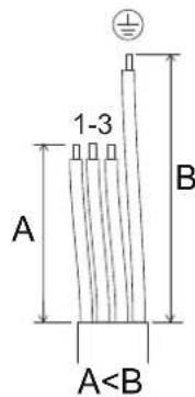

IPEIOCTEPEXKHeN
Pn npocenHnn OdoKnlbHbIX CoeHNHTbHbIX npoBOIOB K KneMMHO KOJOnKe o6raTeNbHO cDenaiTe nTIO. PnpobemPi npa6ote Moryt npnbecTu HArpeBy nNoxapy.
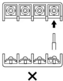
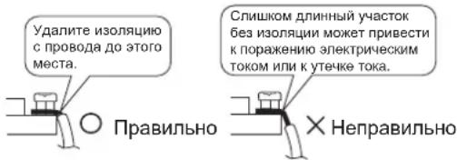
Ha cTOpOHe KIeMMHOn KOJODKn CHMnTe C npOBoJa I3OJIaIIO
3) IopTnHTe 3a npoBOu n y6eNTecb, yTO OH He OTcoeHNHReTc. 3aTeM 3aKpENITE npoBOu Ha MeCTe B 3axmme npoBOOvB.
3neKtpnueckc xema

Knemmmn KOnoKa
:PpoknaIbIaEmaHa MeCTe 3KcNpyatauIN 3NeKTPponpoBODka

:Pa3bEm:KOHueBOB BBIO


:CoeINHeHne
BLK:UeHbI ORG:OpAHHBeBbI
BLU:CNHn RED:KpaChbI
BRN:KopuHHeBbWHT:Bb
GRN
:3eHbH
YLW
:Kentb
PpmeaHn Tpe6oBaHnK 3eKeTpOnHTAnHIO npBHeDeHb Ha nacnpToHt TaBnue arperata.
:OUTDOOR
Hapykhbl
: CONDENSER
KoHdEHCATOp
: DISCHARGE
HaHHeTaHne
Ta6nua kOMnoHeHToB 3NeKtpnueecko CXembl
C1, C2, C400, C405....KoHdeHcaTop
V1R. ⅡIOHbIMoCT
E1, E2, HL1, HN1,
S,HR1,HR2. CoeDInHeHne
FU2, FU3 ...PpeOxpaHnTeB
IPM1, IPM2 .HTeJIeKtYaIbHy b6nok nTaHn
L. 0a3a
L1R PeakTop
M1C ... 3neKtpoBnraTeNb KOMnpccopa
M1F. 3JIeKToPdBnraTeIb BeHTnIaTopa
K30R, K10R, MR4 ....... MarHHtoe pepe
N. Heitpab
A1P. .NeeuTHa nnata
PS. 10ctouHnIHTaHn
Q1M ...YcTpoIcTB0 3aunTbI OT nepepy3kn
R1T, R2T, R3T, PTC ...TepMnctop
S20,S30,S40,
S71,S80,S90..Pa3beM
F1S ...Mmnybchb pa3pndnK
V2,V3. .Bapuctop
X1M. KneMMna KOJIOka
Y1E 3MeeBnK 3JIeKtpoHHoro TepMopepyu npuyoero BeHTnIa
Y1S ...KaTyuKa YeTbIpeXxoOBOrO KnaNaHa
Z1C,Z2C,Z3C. .FeppntoBb cepDeuHnK

3aunTHoe 3a3eMJIeHHe

3emJra
[Yauguyulayin] [Sikin]
| Konik somun sikma torku | |
| Gaz tarafi | Sıvi tarafi |
| 3/8 inc | 1/4 inc |
| 32,7-39,9 N·m(333-407 kgf·cm) | 14,2-17,2 N·m(144-175 kgf·cm) |
| Vana tapası sikma torku | |
| Gaz tarafa | Sıvı tarafa |
| 3/8 inç | 1/4 inç |
| 21,6-27,4 N·m (220-280 kgf·cm) | 21,6-27,4 N·m (220-280 kgf·cm) |
| Servis portu kapaği sikma torku | 10,8~14,7 N·m (110~150 kgf·cm) |