GRIT GX 75 2H - Grinder Fein - Free user manual and instructions
Find the device manual for free GRIT GX 75 2H Fein in PDF.
Frequently Asked Questions - GRIT GX 75 2H Fein
Download the instructions for your Grinder in PDF format for free! Find your manual GRIT GX 75 2H - Fein and take your electronic device back in hand. On this page are published all the documents necessary for the use of your device. GRIT GX 75 2H by Fein.
USER MANUAL GRIT GX 75 2H Fein
mm 75 75 75 75 I I I I
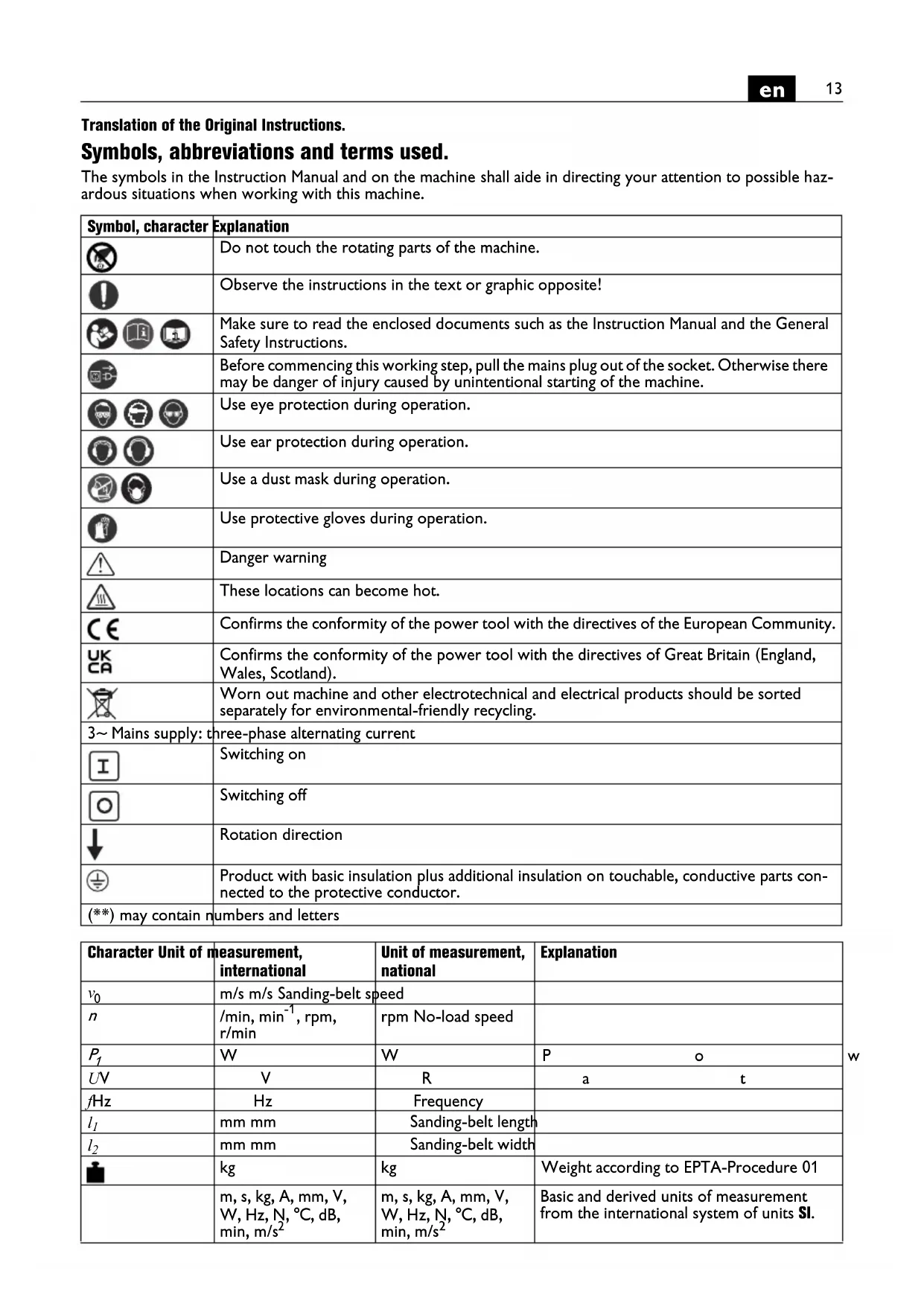
Translation of the Original Instructions. Symbols, abbreviations and terms used. The symbols in the Instruction Manual and on the machine shall aide in directing your attention to possible haz- ardous situations when working with this machine. Symbol, character Explanation Do not touch the rotating parts of the machine. Observe the instructions in the text or graphic opposite! Make sure to read the enclosed documents such as the Instruction Manual and the General Safety Instructions. Before commencing this working step, pull the mains plug out of the socket. Otherwise there may be danger of injury caused by unintentional starting of the machine. Use eye protection during operation. Use ear protection during operation. Use a dust mask during operation. Use protective gloves during operation. Danger warning These locations can become hot. Confirms the conformity of the power tool with the directives of the European Community. Confirms the conformity of the power tool with the directives of Great Britain (England, Wales, Scotland). Worn out machine and other electrotechnical and electrical products should be sorted separately for environmental-friendly recycling. 3~ Mains supply: three-phase alternating current Switching on Switching off Rotation direction Product with basic insulation plus additional insulation on touchable, conductive parts con- nected to the protective conductor. (**) may contain numbers and letters Character Unit of measurement, international Unit of measurement, national Explanation
m/s m/s Sanding-belt speed
, rpm, r/min rpm No-load speed
mm mm Sanding-belt length
Basic and derived units of measurement from the international system of units SI.14
For your safety. Do not use this machine before you have thor- oughly read and completely understood theseop- erating instructions, including the figures, specifications, and safety regulations. Please also observe the relevant national industrial safe- tyregulations (e. g. in Germany: BGV A2, BGR 500). Non-observance of the safety instructions in the said documentation can lead to an electric shock, burns and/or severe injuries. This Instruction Manual should be kept for later use and enclosed with the power tool, should it be passed on or sold. Intended use of the machine. This machine is intended for grinding metal materials (except magnesium) and for grinding with the radius grinding module GRIT GXR or the cylindrical grinding device GRIT GXC using the grinding belts recom- mended by FEIN in weather-protected environments. Special safety instructions. Ensure stable positioning and a level set-up of the sub base. Fasten the sub base to the floor. If the sub base tips over during working, this can cause serious injuries. Use suitable mounting material to mount the machine to the sub base. Faulty assembly can cause the machine to loosen from the sub base during operation and lead to serious accidents. Wear personal protective equipment. Depending on application, use face shield, safety goggles or safety glasses. Where appropriate, wear dust mask, hearing protectors, gloves and workshop apron capable of stop- ping small abrasive or workpiece fragments. The eye protection must be capable of stopping flying debris generated by various operations. The dust mask or res- pirator must be capable of filtrating particles generated by your operation. Prolonged exposure to high inten- sity noise may cause hearing loss. While working, do not wear loose clothing, jewellery or open, long hair. Despite protective devices, loose objects can be snagged or caught by moving parts and lead to injury. Do not use worn, torn or heavily clogged grinding belts. Handle grinding belts carefully and store them accord- ing to the manufacturer’s instructions. Do not bend or fold grinding belts! Damaged grinding belts can tear, be flung away and injure someone. Do not use grinding belts or other accessories which are not specifically designed and recommended by the power tool manufacturer. Safe operation is not ensured merely because a grinding belt or accessory fits your machine. Always use the protective devices attached on the machine. The protective devices must be securely mounted to the machine in order to achieve maximum safety. The protective devices are supposed to protect the user from grinding particles thrown from the machine and from accidental contact with the grinding belt. Warning! Danger of fire and explosion! When grinding metals (e.g., aluminium), dust develops that may be combustible or explosive. Do not operate the machine near flammable materials. Sparks could cause these materials to ignite. Warning! Danger of fire! When grinding metals, glowing metal and sanding-belt particles develop that are col- lected in the chip/grinding-dust box. Before emptying, the contents of the chip/grinding-dust box must have cooled down sufficiently and may only be disposed of in suitable containers. Pay attention that other persons are not put at risk from sparking. Remove flammable materials in close vicinity. Sparking occurs when grinding metal. Keep bystanders a safe distance away from work area. Anyone entering the work area must wear personal pro- tective equipment. Fragments of workpiece or of a bro- ken accessory may fly away and cause injury beyond immediate area of operation. The workpiece must always lie securely on the grinding rest and the stop. Workpieces that are too small or too thin may not be worked. Danger of injury from work- pieces being thrown from the machine. The surface being worked can become very hot. Do not touch it with your hands. Never touch the running grinding belt. Danger of injury. In situations of danger, immediately press the safety pushbutton. The machine runs on for approx. 50 sec- onds. Clean the ventilation openings on the power tool at reg- ular intervals using non-metal tools. The blower of the motor draws dust into the housing. An excessive accu- mulation of metallic dust can cause an electrical hazard. The mains plug of the machine may be mounted only by a qualified electrician. The protective conductor in the mains socket outlet must be connected with the pro- tective earthing of the mains supply. Pull out the mains plug for maintenance and repair! Switching the machine on unintentionally can lead to serious injuries. Have the electrical safety of the machine checked reg- ularly in accordance with statutory regulations. For machines t hat have not been checked, there may be danger of electrical shock! Check the rotation direction of the motor before start- ing the operation of the machine for the first time. If the rotation direction of the motor is incorrect, the work- piece can be thrown from the machine and cause an accident. The rotation direction may be changed only by a qualifiedelectrician. Make sure that you or other persons are not standing directly next to the grinding belt when switching the machine on. The grinding belt can tear apart and cause serious injuries.15
Handling hazardous dusts For work procedures with this power tool where material is removed, dusts develop that can be hazard- ous to one’s health. Contact with or inhaling some dust types, e. g. asbestos and asbestos-containing materials, lead-containing coat- ings, metal, some wood types, minerals, silicate parti- cles from materials containing stone, paint solvents, wood preservatives, antifouling paints for vessels, can trigger allergic reactions to the operator or bystanders and/or lead to respiratory infections, cancer, birth defects or other reproductive harm. The risk from inhaling dusts depends on the exposition. Use dust extraction matched appropriately for the developing dust, as well as personal protective equipment and pro- vide for good ventilation of the workplace. Leave the processing of asbestos-containing materials to special- ists. Wood and light-metal dust, hot mixtures of grinding dust and chemical materials can self-ignite under unfa- vourable conditions or cause an explosion. Avoid sparking in the direction of the dust collector as well as overheating of the power tool and the materials being sanded, empty the dust collector/container in time, observe the material manufacturer’s working instruc- tions, as well as the relevant regulations in your country for the materials being worked. At a glance. 1 Clamping lever, sub base 2 Screw 3 Sub base 4 Safety cover, top 5 Clamping lever, belt tension 6 Star-knob bolt, safety cover 7 Stop 8 Wing bolts of the spark guard 9 Spark guard 10 Grinding rest 11 Dust collector 12 Star-knob bolt for grinding rest 13 Adjustment screw of support surface for plane grinding 14 Star-knob bolt for adjusting the tracking of the grinding belt 15 Safety pushbutton 16 Venting slots 17 On/Off switch 18 Speed reversing switch (only 2H models) 19 Contact wheel 20 Support surface for plane grinding 21 Drive wheel 22 Screw for side cover 23 Side cover 24 Hose connection socket for dust extraction 25 Instruction label 26 Fastening screws for stop Assembly instructions (figure 1). Place the machine on the floor with the top side facing down and mount the sub base according to the figure and the data sheet. Fasten the sub base to the floor using suitable dowel/bolt connections. The connections must withstand the forces that arise during working. Faulty assembly can cause the machine to tip over dur- ing operation and lead to serious accidents. Because of the risk of accidents, this work must be carried out by persons who are physically able to lift the high machine weight. Electrical connection. The electrical connection, which is to be pro- vided by customer, must be carried out by a qual- ified electrician. Observe mains voltage: The mains voltage and the fre- quency of the power source must agree with the data onthe type plate of the machine. Before starting operation for the first time, check the rotation direction of the motor. The rotation direction may be changed only by a qualified electrician. Adjustments. Before any work on the machine itself, pull the mains plug. Adjusting the incline (figure 9). Loosen both clamping levers (1). Set the machine to the required working height. Tighten both clamping levers (1) again. Adjusting the grinding rest (10)(figure 4). Loosen star-knob bolt (12) and adjust the gap size to 2 mm (max.). Tighten the star-knob bolt again. Adjusting the support surface for plane grinding (20). For plane grinding, the support surface for plane grind- ing (20) must be aligned parallel to the grinding belt and face against it over the complete surface. Loosen screw (22) and fold down the side cover (23). Loosen the screws (13) and align the support surface for plane grinding (20). Tighten screws (13) again. Shut the side cover (23) and tighten screw (22) again. Adjust the gap clearance at the stop (7) to max. 2 mm; for this, loosen screws (26), adjust the stop (7) and tighten the screws (26) again. (figure 5) Adjusting the belt tracking. Switch the machine on only briefly and check the belt tracking. If the grinding belt moves left or right, adjust the belt tracking with the starknob bolt (14) until centred. If the belt tracking cannot be adjusted centred: Clean the drive wheel (21) and the contact wheel (19) with compressed air. Check the drive wheel and the contact wheel for wear, deformation and damage. Have damaged components replaced without delay!16
Replacing the grinding belt. Before any work on the machine itself, pull the mains plug. Loosen screw (22) and fold down the side cover (23). (figure 3) Loosen star-knob bolt (12) and remove the chip/grind- ing-dust box (11). Tilt lever (5) down to release the tensioning device. Remove the old grinding belt. Before mounting the new grinding belt, observe the running-direction indication on the rear of the grinding belt! It mus correspond with the rotation direction of the drive wheel. Place the grinding belt both around the drive wheel (21) and around the contact wheel (19). Tilt lever (5) upward to tension the grinding belt. Shut the side cover (23) and tighten screw (22) again. Mount the chip/grinding-dust box (11) and check the gap c learance of the grinding rest.(figure 4) Switch the machine on and adjust the belt run. Operating instructions. Switching on: Disengage and fold up the safety pushbutton (15). Press pushbutton “I” (17). Switching off: Fold up safety pushbutton (15). Press pushbutton “0” (17). After switching off, the machine runs on for approx. 50 seconds. Safety pushbutton: In situations of danger, press the safety pushbutton to switch the machine off. Reversing the speed (2H models) Switch position 1: Low speed Switch position 2: High speed The speed may only be reversed with switch (18) when the machine is stopped. Overload protection. In case of continuous high load over a longer period of time, the machine is switched off. After a cooling-down period of approx. 15 minutes, the machine is ready for operation again. Contact grinding (figures 6 + 7). Check if the star-knob bolt (12) is firmly tightened. Make sure that the top safety cover (4) is secured with star-knob bolt (6) and the side cover (23) is closed. Check the gap size of the grinding rest. Check the position of the support surface for plane grinding (20). The screws (13) must be in the lower position. Check if the wing bolts (8) of the spark guard (9) are properly tightened. Switch the machine on and check the belt run. Place the workpiece firmly onto the grinding rest. Guide the workpiece with both hands or fasten it in a fixture. Plane grinding (figure 8) Loosen star-knob bolts (6) and remove the top safety cover (4). Ensure that the gap clearance is correctly adjusted. (figure 5) Switch the machine on and check the belt run. Guide the workpiece with both hands and remove it upwards after the working procedure. Extraction device We recommend the use of an extraction device. The machine can be connected via sleeve (24) to an exhauster. Noise emission values. Repair and customer service. Repairs may be carried out only by qualified per- sons in conformity with the valid regulations. For repairs, we recommend our FEIN customer service centre, the FEIN authorised service centres and FEIN agencies. When the machine's power supply cable is damaged, it must be replaced using a specially prepared power sup- ply cable, available from your FEIN customer service agent. The current spare parts list of this machine can be found on the Internet under www.fein.com. Idle Sanding A-weighted emission pressure pow er level measured at th
in decibels 4 4 Measured A-weighted sound power level L
GRIT by Fein 36Z REMARK: The sum of the measured emission value and respective measuring inaccuracy represents the upper limit of the values that can occur during measuring. Wear hearing protection! Measured values determined in accordance with the corresponding product standard (see last page in this Instruction Manual).17
Daily maintenance Blow out the ventilation slots (16) at the motor housing and the marked locations with com- pressed air (see Instruction label (25)). Lubricate the machine daily (when in use) with machine oil at the locations marked (see Instruc- tion label (25)). Check the drive disc (21) and the contact disc (19) for wear and damage each time when replacing a grinding belt. Have damaged parts replaced. Loosen star-knob bolt (12). Remove the chip/grinding-dust box (11) and dispose of the metal dust. Before emptying, the contents of the chip/grinding-dust box must have cooled down sufficiently and may only be disposed of in suitable containers. Mount the emptied chip/grinding-dust box again and set the gap clearance of the grinding rest.(figure 4) Tighten star-knob bolt (12). Cleaning the exterior of the machine with compressed air. If required, you can change the following parts your- self: Grinding belt, spark guard (9) Warranty and liability. The warranty for the product is valid in accordance with the legal regulations in the country where it is mar- keted. In addition, FEIN also provides a guarantee in accordance with the FEIN manufacturer’s warranty dec- laration. The delivery scope of your machine may include only a part of the accessories described or shown in this instruction manual. Declaration of conformity. This CE declaration is only valid for European Union and EFTA (European Free Trade Association) countries and only for products intended for the EU- or EFTA market. After placing the product on the EU market the UKCA mark loses its mark validity. The UKCA declaration is only valid for the Great Britain market (England, Wales and Scotland) and only for products intended for the Great Britain market. After placing the product on the Great Britain market the CE mark loses its mark validity. FEIN declares itself solely responsible for this product conforming with the relevant provisions given on the last page of this Instruction Manual. Technical documents at: C. & E. Fein GmbH, D-73529 Schwäbisch Gmünd Environmental protection, disposal. Packaging, worn out machines and accessories should be sorted for environment-friendly recycling. Connection diagrams. Type GX75 Page 99 Type GX752V Page 100 Type GX752H Page 101 Type GX752H2V Page 10218
Director of Quality Director of Product Management Development