
HP2034 - Drill MAKITA - Free user manual and instructions
Find the device manual for free HP2034 MAKITA in PDF.

| Product type | Hammer drill |
| Brand | Makita |
| Model | HP2034 |
| Drilling capacity (concrete) | 20 mm (high speed) |
| Drilling capacity (steel) | 8 mm (high speed), 13 mm (low speed) |
| Drilling capacity (wood) | 25 mm (high speed), 40 mm (low speed) |
| No-load speed (high) | 0 – 2,900 rpm |
| No-load speed (low) | 0 – 850 rpm |
| Impact rate (high) | 0 – 32,000 blows/min |
| Impact rate (low) | 0 – 9,400 blows/min |
| Overall length | 370 mm |
| Net weight | 2.5 kg |
| Power supply | Single-phase mains (voltage per nameplate); double insulation |
| Chuck type | Keyed chuck (3 holes) |
| Mode selector | Rotation only or hammering with rotation |
| Speeds | 2 speeds (selector) |
| Rotation direction switch | Yes |
| Side handle | Yes, 360° adjustable |
| Depth rod | Yes, adjustable |
| Sound pressure level (LpA) | 98 dB(A) |
| Sound power level (LwA) | 111 dB(A) |
| Vibration (weighted acceleration) | 8 m/s² |
| Maintenance | Regular cleaning of air vents; repairs by an authorized Makita service center |
| Included accessories | Chuck key, side handle, depth rod, blow-out bulb |
Frequently Asked Questions - HP2034 MAKITA
User questions about HP2034 MAKITA
0 question about this device. Answer the ones you know or ask your own.
Ask a new question about this device
Download the instructions for your Drill in PDF format for free! Find your manual HP2034 - MAKITA and take your electronic device back in hand. On this page are published all the documents necessary for the use of your device. HP2034 by MAKITA.
USER MANUAL HP2034 MAKITA
natural_image
Line drawing of a power tool with handle and screwdriver (no text or symbols)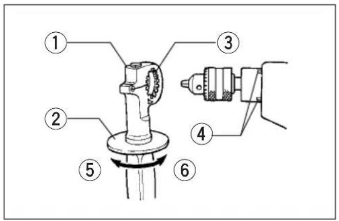
1
2
3
4
5
6
7
8
9
natural_image
Line drawing of a power tool with labeled parts (18), no text or symbols present10
Symbols
The following show the symbols used for machine. Be sure that you understand their meaning before use
Symboles
Explanation of general view
① Grip base
② Side grip (auxiliary handle)
③ Teeth
④ Protrusions
⑤ Loosen
⑥ Tighten
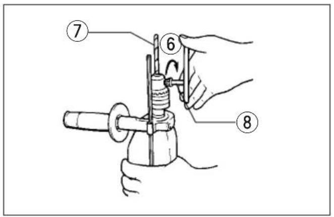
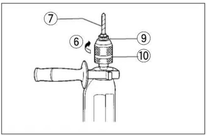
⑦ Bit
⑧ Chuck key
⑨ Sleeve
⑩ Ring
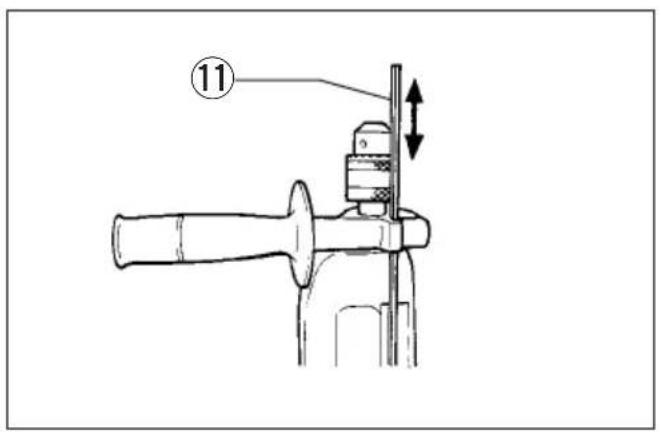
⑪ Depth gauge
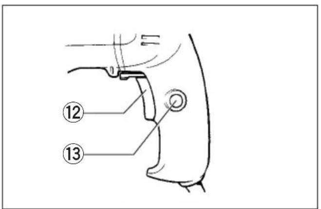
⑫ Switch trigger
⑬ Lock button
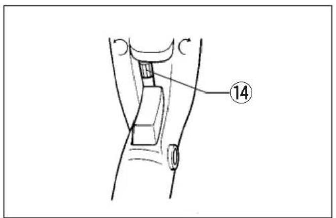
⑭ Reversing switch lever
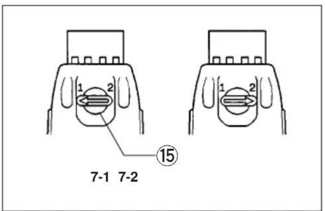
⑮ Speed change knob
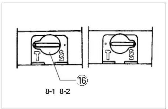
⑯ Action mode change knob
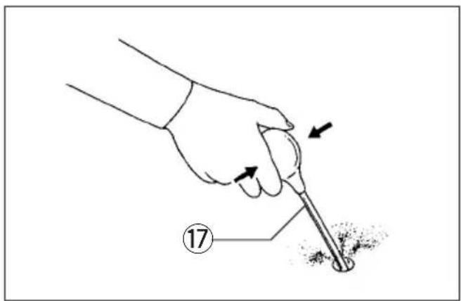
⑰ Blow-out bulb
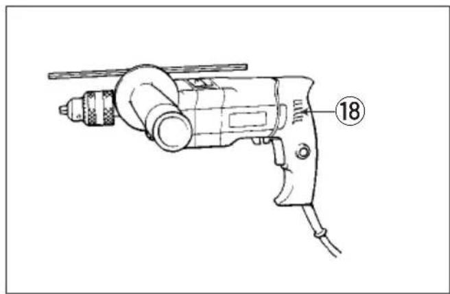
⑱ Vent holes
SPECIFICATIONS
Model HP2032 HP2033 HP2034
Max. capacities
| Concrete | High: 20 mm 20 mm 20 mm | ||
| Low: — — — | |||
| Steel | High: 8 mm 8 mm 8 mm | ||
| Low: 13 mm 13 mm 13 mm | |||
| Wood | High: 25 mm 25 mm 25 mm | ||
| Low: 40 mm 40 mm 40 mm | |||
| o load speed (RPM) | High: 0 – 2,900 | 0 – 2,900 | 2,900 |
| Low: 0 – 850 | 0 – 850 | 850 | |
| lows per minute | High: 0 – 32,000 | 0 – 32,000 | 32,000 |
| Low: 0 – 9,400 | 0 – 9,400 | 9,400 | |
| overall length | 370 mm | 368 mm | 370 mm |
| et weight | 2.5 kg | 2.5 kg | 2.5 kg |
- Due to our continuing program of research and development, the specifications herein are subject to change without notice.
- Note: Specifications may differ from country to country.
Power supply
The machine should be connected only to a power supply of the same voltage as indicated on the nameplate, and can only be operated on single-phase
AC supply. They are double-insulated in accordance with European Standard and can, therefore, also be used from sockets without earth wire.
Safety hints
For your own safety, please refer to the enclosed safety instructions.
ADDITIONAL SAFETY RULES
- Wear a hard hat (safety helmet), safety glasses and/or face shield. It is also highly recommended that you wear a dust mask, ear protectors and thickly padded gloves.
- Under normal operation, the machine is designed to produce vibration. The screws can come loose easily, causing a breakdown or accident. Check tightness of screws carefully before operation.
- Always be sure you have a firm footing. Be sure no one is below when using the machine in high locations.
- Hold the machine firmly with both hands. Always use the side grip.
- Keep hands away from rotating parts.
-
Do not leave the machine running. Operate the machine only when hand-held.
-
When drilling into walls, floors or wherever "live" electrical wires may be encountered, DO NOT TOUCH ANY METAL PARTS OF THE MACHINE! Hold the machine only by the insulated grasping surfaces to prevent electric shock if you drill into a "live" wire.
- Do not touch the bit or the workpiece immediately after operation; they may be extremely hot and could burn your skin.
SAVE THESE INSTRUCTIONS.
OPERATING INSTRUCTIONS
Important:
Always be sure that the machine is switched off and unplugged before installing or removing the side grip, bit or other accessories.
Side grip (auxiliary handle) (Fig. 1)
Always use the side grip to ensure operating safety. Install the side grip so that the teeth on the grip fit in between the protrusions on the machine barrel. Then tighten the grip by turning clockwise at the desired position. It may be swung 360° so as to be secured any position.
Installing or removing drill bit
For HP2032 and HP2034 (Fig. 2)
To install the bit, place it in the chuck as far as it w go. Tighten the chuck by hand. Place the chuck key in each of the three holes and tighten clockwise. Be sure to tighten all three chuck holes evenly.
To remove the bit, turn the chuck key counterclockwise in just one hole, then loosen the chuck by hand. After using the chuck key, be sure to return it to the original position.
For HP2033 (Fig. 3)
Hold the ring and turn the sleeve counterclockwise open the chuck jaws. Place the bit in the chuck as it will go. Hold the ring firmly and turn the slee clockwise until the chuck is tightened with a little c After the click, always tighten the chuck additionally prevent accidental loosening during operation.
To remove the bit, hold the ring and turn the slee counterclockwise.
Depth gauge (Fig. 4)
The depth gauge is convenient for drilling holes of uniform depth. Loosen the side grip and insert the depth gauge into the hole in the side grip. Adjust depth gauge to the desired depth and tighten the grip.
NOTE:
The depth gauge cannot be used at the position where the depth gauge strikes against the gear housing.
Switch action (Fig. 5)
CAUTION:
Before plugging in the machine, always check to see that the switch trigger actuates properly and returns to the "OFF" position when released.
For HP2032 and HP2033
To start the machine, simply pull the trigger. Machine speed is increased by increasing pressure on the trigger. Release the trigger to stop. For continuous operation, pull the trigger and then push in the lock button. To stop the machine from the locked position, pull the trigger fully, then release it.
For HP2034
To start the machine, simply pull the trigger. Release the trigger to stop. For continuous operation, pull the trigger and then push in the lock button. To stop the machine from the locked position, pull the trigger fully, then release it.
Reversing switch action (Fig. 6)
For HP2032 and HP2033
CAUTION:
• Always check the direction of rotation before operation.
- Use the reversing switch only after the machine comes to a complete stop. Changing the direction of rotation before the machine stops may damage the machine.
This machine has a reversing switch to change the direction of rotation. Move the reversing switch lever to the ⏻ position for clockwise rotation or the ⏻ position for counterclockwise rotation.
Speed change knob (Fig. 7)
Two rpm ranges can be preselected with the speed change knob. Turn the speed change knob to the position 1 or position 2.
Position 1:0 - 850 rpm (Fig. 7-1)
Position 2:0 - 2,900 rpm. (Fig. 7-2)
If it is hard to turn the knob, first turn the chuck slightly in either direction and then turn the knob again.
Selecting action mode (Fig. 8)
This machine has an action mode change knob. For rotation with hammering, turn the action mode change knob to the position of symbol. (Fig. 8-1) If for rotation only, turn the action mode change knob to the position of symbol. (Fig. 8-2)
CAUTION:
Always turn the action mode change knob all the way to your desired mode position. If you operate the machine with the kob positioned half-way between the mode symbols, the machine may be damaged.
Operation
Hammer drilling operation
When drilling in concrete, granite, tile, etc., turn the action mode change knob to the position of symbol to use “rotation with hammering” action. Be sure to use a tungsten-cabide tipped bit. Do not apply more pressure when the hole becomes clogged with chips or particles. Instead, run the machine at an idle, then remove the bit partially from the hole. By repeating this several times, the hole will be cleaned out.
After drilling the hole, use the blow-out bulb to clean the dust out of the hole. (Fig. 9)
2) Drilling operation
When drilling in wood, metal or plastic materials, turn the action mode change knob to the position of ☐ symbol to use “rotation only” action.
- Drilling in wood
When drilling in wood, best results are obtained with wood drills equipped with a guide screw. The guide screw makes drilling easier by pulling the bit into the workpiece.
- Drilling in metal
To prevent the bit from slipping when starting a hole, make an indentation with a centerpunch and hammer at the point to be drilled. Place the point of the bit in the indentation and start drilling.
Use a cutting lubricant when drilling metals. The exceptions are iron and brass which should be drilled dry.
CAUTION:
- Pressing excessively on the machine will not speed up the drilling. In fact, this excessive pressure will only serve to damage the tip of your bit, decrease the machine performance and shorten the service life of the machine.
- There is a tremendous twisting force exerted on the machine/bit at the time of hole breakthrough. Hold the machine firmly and exert care when the bit begins to break through the workpiece.
- A stuck bit can be removed simply by setting the reversing switch to reverse rotation in order to back out. However, the machine may back out abruptly if you do not hold it firmly.
• Always secure small workpieces in a vise or similar hold-down device.
MAINTENANCE
CAUTION:
Always be sure that the machine is switched off and unplugged before carrying out any work on the machine.
Cleaning vent holes (Fig. 10)
Periodically clean the vent holes to prevent them from being clogged with dust, dirt or the like.
To maintain product safety and reliability, repairs, maintenance or adjustment should be carried out by a Makita Authorized Service Center.
FRANÇAIS
Descriptif
Model HP2032 HP2033 HP2034
| Kapacitet | |||
| Beton | Høj: 20 mm 20 mm 20 mmLav: — — — | ||
| Stål | Høj: 8 mm 8 mm 8 mmLav: 13 mm 13 mm 13 mm | ||
| Træ | Høj: 25 mm 25 mm 25 mmLav: 40 mm 40 mm 40 mm | ||
| Omdrejninger | Høj: 0 – 2 900 0 – 2 900 2 900Lav: 0 – 850 0 – 850 | 850 | |
| Slag pr minut | Høj: 0 – 32 000 0 – 32 000Lav: 0 – 9 400 0 – 9 400 9 400 | 32 000 | |
| Længde | 370 mm 368 mm | 370 mm | |
| Vægt | 2,5 kg 2,5 kg | 2,5 kg | |
Malli HP2032 HP2033 HP2034
Model HP2032 HP2033 HP2034
Anahtar is lemleri (S, ekil 5)
DIKKAT:
These accessories or attachments are recommended for use with your Makita machine specified in this manual. The use of any other accessories or attachments might present a risk of injury to persons. The accessories or attachments should be used only in the proper and intended manner.
F ACCESSOIRES
ATTENTION :
EC-DECLARATION OF CONFORMITY
The undersigned, Yasuhiko Kanzaki, authorized by Makita Corporation, 3-11-8 Sumiyoshi-Cho, Anjo, Aichi, 446 Japan declares that this product
(Serial No.: series production) manufactured by Makita Corporation in Japan is in compliance with the following standards or standardized documents,
HD400, EN50144, EN55014, EN61000* in accordance with Council Directives, 73/23/EEC, 89/336/EEC and 98/37/EC.
*from 1st Jan. 2001
FRANÇAISE
DÉCLARATION DE CONFORMITÉ CE
Michigan Drive, Tongwell, Milton Keynes, Bucks MK15 8JD, U.K.
PORTUGUÊS
EU-DEKLARATION OM KONFORMITET
Michigan Drive, Tongwell, Milton Keynes,
Bucks MK15 8JD, U.K.
ENGLISH
Noise And Vibration Of Model HP2032 / HP2033 / HP2034
The typical A-weighted noise levels are
sound pressure level: 98 dB (A)
sound power level: 111 dB (A)
— Wear ear protection. —
The typical weighted root mean square acceleration value is 8 m/s ^2 .
FRANÇAISE

- Symbols
- Symboles
- Explanation of general view
- SPECIFICATIONS
- Model HP2032 HP2033 HP2034
- Power supply
- Safety hints
- ADDITIONAL SAFETY RULES
- SAVE THESE INSTRUCTIONS.
- OPERATING INSTRUCTIONS
- Side grip (auxiliary handle) (Fig. 1)
- Installing or removing drill bit
- For HP2032 and HP2034 (Fig. 2)
- For HP2033 (Fig. 3)
- Depth gauge (Fig. 4)
- NOTE:
- Switch action (Fig. 5)
- CAUTION:
- For HP2032 and HP2033
- For HP2034
- Reversing switch action (Fig. 6)
- Speed change knob (Fig. 7)
- Selecting action mode (Fig. 8)
- Operation
- 2) Drilling operation
- MAINTENANCE
- Cleaning vent holes (Fig. 10)
- FRANÇAIS
- Descriptif
- Malli HP2032 HP2033 HP2034
- Anahtar is lemleri (S, ekil 5)
- F ACCESSOIRES
- ATTENTION :
- EC-DECLARATION OF CONFORMITY
- FRANÇAISE
- DÉCLARATION DE CONFORMITÉ CE
- PORTUGUÊS
- EU-DEKLARATION OM KONFORMITET
- ENGLISH
Brand : MAKITA
Model : HP2034
Category : Drill