EB7650TH - Leaf blower MAKITA - Free user manual and instructions
Find the device manual for free EB7650TH MAKITA in PDF.

Frequently Asked Questions - EB7650TH MAKITA
User questions about EB7650TH MAKITA
0 question about this device. Answer the ones you know or ask your own.
Ask a new question about this device
Download the instructions for your Leaf blower in PDF format for free! Find your manual EB7650TH - MAKITA and take your electronic device back in hand. On this page are published all the documents necessary for the use of your device. EB7650TH by MAKITA.
USER MANUAL EB7650TH MAKITA
Original Instruction Manual
Read this instruction manual carefully before putting the Blower into operation and strictly observe the safety regulations! Preserve instruction manual carefully!
Importante:
natural_image
Line drawing of a handheld industrial device with hoses and a cylindrical shaft (no text or symbols)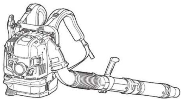
natural_image
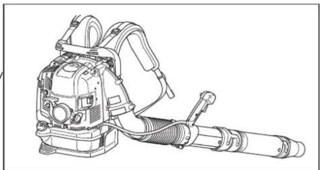
Line drawing of a handheld industrial machine with hoses and a long cylindrical component (no text or symbols)EB7650TH EB7650WH
English
Thank you very much for selecting the Makita blower. We are pleased to be able to offer you the Makita blower, which is the result of a long development program and many years of knowledge and experience.
Those blower models combine the advantages of state-of-the-art technology with ergonomic design. They are of lightweight, handy, compact and represent professional equipment for a great variety of applications.
Please read, understand and follow this booklet, which refers in detail to the various points that will demonstrate its outstanding performance. This will assist you to safety obtain the best possible results from your Makita Blower.

Table of Contents
Page
Symbols....2
Safety instructions .... 3
EC declaration of conformity 6
Technical data....7
Designation of parts....8
Assembly instructions....9
Before starting the engine 10
Operation 12
Adjustment of idling 14
Prevention from carburetor icing 14
Operation method....15
Inspection and maintenance.... 17
Storage 19
Troubleshooting....21
SYMBOLS
It is very important to understand the following symbols when reading this instructions manual.

WARNING/DANGER Keep bystanders away


Read, Understand and Follow Instruction Manual
Fuel (Gasoline)

Forbidden Engine-manual Start

No Smoking Emergency Stop

No Open Flame First Aid


Protective Gloves must be Worn ON/START


Keep the Area of Operation Clear of All Persons and Pets

OFF/STOP

Wear Eye and Ear Protection Severing of fingers or hand. In a peller blade


Hot surfaces – Burns to fingers or hands
Long hair may cause entanglement accident.
SAFETY INSTRUCTIONS
General Instructions
- To ensure correct and safe operation, the user must read, understand and follow this instruction manual to assure familiarity with the handling of the blower (1). Users insufficiently informed will risk danger to themselves as well as others due to improper handling.
- It is recommended only to loan the blower to people who have proven to be experienced with blowers.
• Always hand over the instruction manual. - First-time users should ask the dealer for basic instructions to familiarize oneself with the handling of a blower.
- Children and young persons aged under 18 years must not be allowed to operate the blower. Persons over the age of 16 years may however use the tool for the purpose of being trained only while under the direct supervision of a qualified trainer.
- Use blowers with the utmost care and attention.
- Operate the blower only if you are in good physical condition.
- Perform all work conscientiously and carefully. The user has to accept responsibility for others.
- Never use the blower while under the influence of alcohol or drugs (2).
- Do not use the unit when you are tired.
- Save these instructions for future referral.
Personal Protective Equipment
- The clothing worn should be functional and appropriate, i. e., it should be tight fitting but not cause a hindrance. Do not wear jewelry, clothing or long hair which could be drawn into the air intake.
- In order to avoid head-, eye-, hand- or foot injuries as well as to protect your hearing the following protective equipment and protective clothing must be used during operation of the blower.
Pay particular attention to the following regulations
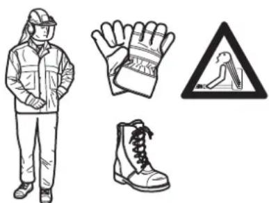
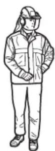
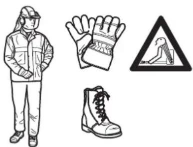
- Clothing must be sturdy and snug-fitting, but allow complete freedom of movement. Avoid loose-fitting jackets, flared or cuffed pants, scarves, unconfined long hair or anything that could be drawn into the air intake. (4) Wear overalls or long pants to protect your legs. Do not wear shorts. (4)
- Generally, engine products are noisy and their noise may damage your hearing. Wear sound barriers (ear plugs or ear mufflers) to protect your hearing. Continual and regular users should have their hearing checked regularly. (3)
- Use of gloves when working with the blower is recommended. Wear sturdy shoes with non-slip soles. (4)
- Proper eye protection is a must. Even though the discharge is directed away from the operator, ricochets and bounce-backs can occur during blower operation. (3)
- Never operate a blower unless wearing goggles or properly fitted safety glasses with adequate top and side protection which comply with EN166 and regulations in your country.
- To reduce the risk of injury associated with the inhalation of dust, use face filter mask in dusty conditions.
Starting up the blower
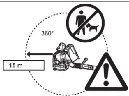
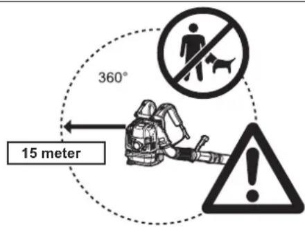
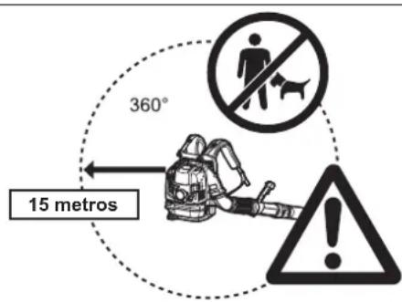
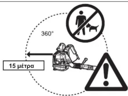
- Make sure that there are no children or other people within a working range of 15 meters (5), also pay attention to any animals in the working vicinity. Never use the blower in urban areas.
- Before operating, always check that the blower is safe for operation: Check the security of the throttle lever. The throttle lever should be checked for smooth and easy action. Check for proper functioning of the throttle lever lock. Check for clean and dry handles and test the function of the I-O switch. Keep handles free of oil and fuel.
natural_image
Two symbolic icons: an open book and a triangular warning sign with an exclamation mark (no text or labels)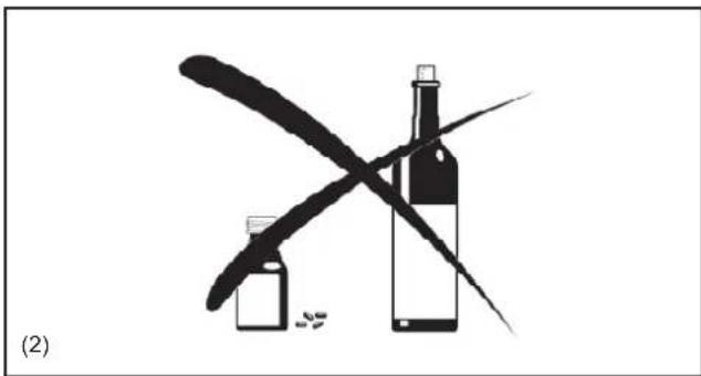
natural_image
Black-and-white illustration of a wine bottle crossed out by a pen, with scattered pills and a cross mark (no text or symbols)
natural_image
Two black-and-white illustrations: a pair of glasses and a pair of headphones, both without any text or symbols.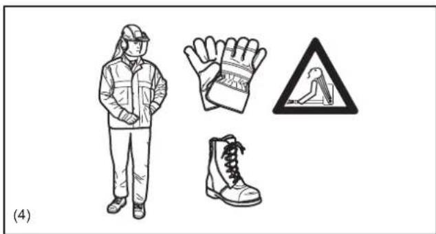
natural_image
Illustration of a worker wearing protective gear, gloves, and boots (no text or symbols)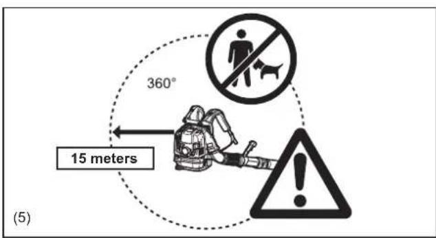
text_image
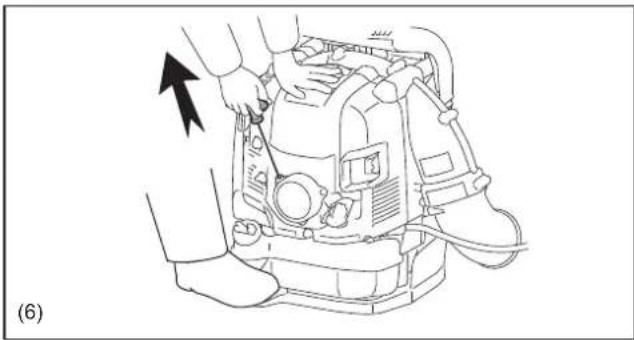
360° 15 meters (5)- Start the Blower only in accordance with the instructions. Do not use any other methods for starting the engine (6).
- Use the blower and the tools supplied only for applications specified.
- Start the blower engine only after the entire tool has been assembled. Operation of the tool is permitted only after all the appropriate accessories are attached.
- The engine is to be switched off immediately if there are any engine problems.
- When working with the blower, always wrap your fingers tightly around the handle, keeping the control handle cradled between your thumb and forefinger. Keep your hand in this position to have your machine under control at all times. Make sure your control handle is in good condition and free of moisture, pitch, oil or grease. Always ensure a safe, well-balanced footing.
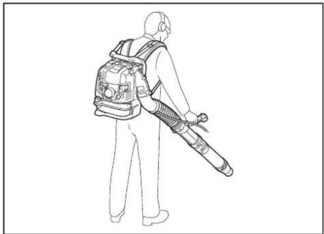
- Carry the blower properly on both shoulders during operation. Do not carry the blower with only one shoulder strap. Otherwise personal injury may result.
- Operate the blower in such a manner as to avoid inhalation of the exhaust gases. Never run the engine in enclosed rooms (risk of suffocation and gas poisoning). Carbon monoxide is an odorless gas. Always ensure there is adequate ventilation.
- Switch off the engine when resting or leaving the blower unattended. Place it in a safe location prevent danger to others, setting fire to combustible materials, or damage to the machine.
- Never lay the hot blower onto dry grass or onto any combustible materials.
- All protective parts and guards supplied with the machine must be used during operation.
- Never operate the engine with a faulty exhaust muffler.
- Shut off the engine during transport (7).
- Position the blower safely during car or truck transportation to avoid fuel leakage.
- When transporting the blower, ensure that the fuel tank is completely empty.
- Carry the blower by its carry handle. Do not drag the blower by nozzle, pipe or other parts.
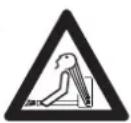
- When transport the blower, bent your knee and make sure you do not damage your shoulder and lower back.
Refuelling
- Shut off the engine during refuelling (7), keep well away from open flame (8) and do not smoke.
- Avoid skin contact with petroleum products. Do not inhale fuel vapor. Always wear protective gloves during refuelling. Change and clean protective clothing at regular intervals.
- Take care not to spill either fuel or oil in order to prevent soil contamination (environmental protection). Clean the blower immediately after fuel has been spilt. Allow wet cloths to dry before disposing in properly, covered container to prevent spontaneous combustion.
- Avoid any fuel contact with your clothing. Change your clothing immediately if fuel has been spilled on it (fire hazard).
- Inspect the fuel cap at regular intervals making sure that it stays securely fastened.
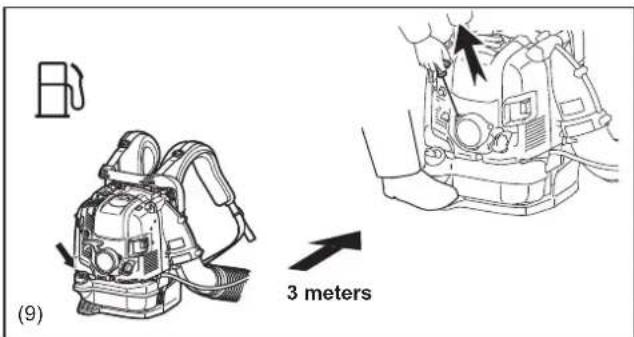
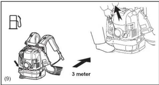
- Carefully tighten the locking screw of the fuel tank. Change locations to start the engine (at least 3 meters away from the place of refuelling) (9).
- Never refuel in closed rooms. Fuel vapors accumulate at ground level (risk of explosions).
- Only transport and store fuel in approved containers. Make sure stored fuel is not accessible to children.
- Do not attempt to refuel a hot or a running engine.
natural_image
Line drawing of a mechanical device with hands and a black arrow indicating a component (no text or symbols)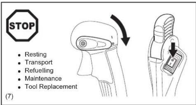
text_image
STOP • Resting • Transport • Refuelling • Maintenance • Tool Replacement (7)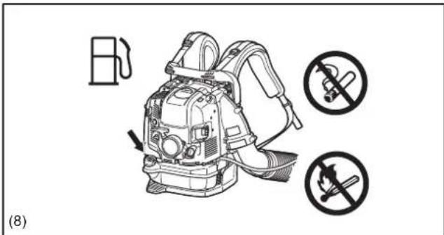
text_image
(8)
text_image
(9) 3 metersMethod of operation
- Use the blower only in good light and visibility. Beware of slippery or wet areas, ice and snow (risk of slipping), and narrow space.
Always ensure a safe footing. - Never work on unstable surfaces or steep terrain.
- Do not work from ladders or high places. Otherwise it may result in personal injury.
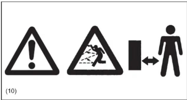
- To reduce the risk of personal injury, do not direct air blast towards bystanders, since the high pressure of the air flow could injure eyes and could blow small objects at great speed.
- Never insert any foreign object into the air intake of the machine or into the nozzle of the blower. It will damage the fan wheel and may cause serious injury to the operator or bystanders as a result of the object or broken parts being thrown out at high speed.
- Pay attention to the direction of the wind, i.e., do not work against the wind.
- To reduce the risk of stumbling and loss of control, do not walk backward while operating the machine.
- Always shut off the engine before cleaning or servicing the unit or replacing parts.
- Take a rest to prevent loss of control caused by fatigue. We recommend to take a 10 to 20-minute rest every hour.
- Do not operate the machine near the windows, etc.
- To reduce damage from vibration and/or damage to the ears, operate the machine at low speed if possible and limit the time of operation.
- Operate the machine only at reasonable hours. Do not operate the blower in the morning or late at night when people might be disturbed.
- It is recommended for using rakes and brooms to loosen debris before blowing.
- Before blowing, slightly dampen surfaces in dusty conditions or use water mist sprayer if necessary.
- Adjust the length of the blower nozzle so that the stream can work close to the ground.
- To reduce sound levels, limit the number of pieces of equipment used at any one time.
After using blowers and other equipment, CLEAN UP! Dispose of debris in trash receptacles.
Maintenance instructions
- Be kind to the environment. Operate the blower with as little noise and pollution as possible. In particular, check the correct adjustment of the carburetor.
- Clean the blower at regular intervals and check that all screws and nuts are securely tightened.
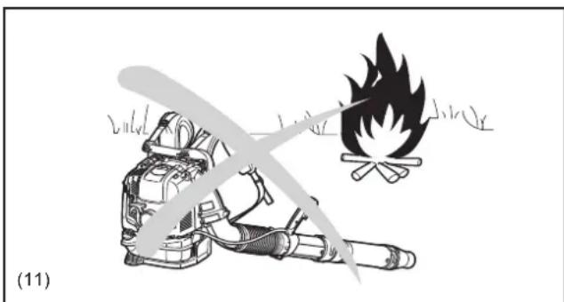
- Never service or store the blower in the vicinity of open flames, sparks, etc. (11).
- Always store the blower in a well-ventilated locked room and with an emptied fuel tank.
Observe and follow all relevant accident prevention instructions issued by the trade associations and by insurance companies. Do not perform any modifications to the blower as this will risk your safety.
The performance of maintenance or repair work by the user is limited to those activities as described in this instruction manual. All other work is to be done by Authorized Service Agents.
Use only genuine spare parts and accessories supplied by Makita.
Use of non-approved accessories and tools means increased risk of accidents and injuries. Makita will not accept any liability for accidents or damage caused by the use of any non-approved attachment or accessories.
Never make modification on the equipment. It may cause dangerous accidents or personal injury.
text_image
(10)
natural_image
Illustration of a firefighter with a helmet and fire symbol (no text or labels)First Aid
In case of accident make sure that a well-stocked first-aid kit is available in the vicinity of the operations. Immediately replace any item taken from the first aid kit.
When asking for help, please give the following information:
- Place of accident
• What happened
• Number of injured persons - Extent of injuries
- Your name

natural_image
Simple black square with a white cross symbol in the center (no text or numbers)(12)
For European countries only
EC Declaration of Conformity
We Makita Corporation as the responsible manufacturer declare that the following Makita machine(s):
Designation of Machine: Petrol Blower
Model No./ Type: EB7650TH, EB7650WH
Specifications: see "TECHNICAL DATA" table
are of series production and
Conforms to the following European Directives:
2000/14/EC, 2006/42/EC
And are manufactured in accordance with the following standards or standardized documents:
EN15503
The technical documentation is kept by our authorized representative in Europe who is:
Makita International Europe Ltd.
Michigan Drive, Tongwell, Milton Keynes, Bucks MK15 8JD, England
The conformity assessment procedure required by Directive 2000/14/EC was in Accordance with annex V.
Measured Sound Power Level: 110 dB
Guaranteed Sound Power Level: 111 dB
6.8.2013

Tomoyasu Kato
Director
Makita Corporation
3-11-8, Sumiyoshi-cho,
Anjo, Aichi, JAPAN
TECHNICAL DATA
| Model EB7650TH EB7650WH | |||||||
| Throttle type Tube throttle Hip throttle | |||||||
| Mass (without blower pipe) (kg) 10.8 11.0 | |||||||
| Dimension (without blower pipe L x W x H) (mm) 332 x 460 x 480 332 x 510 x 480 | |||||||
| Air velocity | (with long pipe) | (with speed nozzle) | (m/s) | 89 | |||
| (with volume nozzle) 81 | |||||||
| (with flat nozzle) 86 | |||||||
| (with short pipe) | (with speed nozzle) 90 | ||||||
| (with volume nozzle) 81 | |||||||
| (with flat nozzle) 87 | |||||||
| Air volume flow rate | (with long pipe) | (with speed nozzle) | ( m^3/minute ) | 17 | |||
| (with volume nozzle) 19 | |||||||
| (with flat nozzle) 17 | |||||||
| (with short pipe) | (with speed nozzle) 17 | ||||||
| (with volume nozzle) 19 | |||||||
| (with flat nozzle) 17 | |||||||
| Max. engine speed (with speed nozzle) ( min^-1 ) | 7,100 | ||||||
| Idling speed ( min^-1 ) | 2,800 | ||||||
| Engine displacement ( cm^3 ) | 75.6 | ||||||
| Fuel | Automobile gasoline | ||||||
| Fuel tank capacity ( cm^3 ) | 1,900 | ||||||
| Engine oil | API grade SF class or higher, SAE 10W-30 oil (automobile 4-stroke engine oil) | ||||||
| Engine oil volume ( cm^3 ) | 220 | ||||||
| Carburetor (type) | Diaphragm | ||||||
| Spark plug | NGK CMR6A | ||||||
| Electrode gap (mm) | 0.7 - 0.8 | ||||||
| Vibration per EN15503 2009 | Right handle | a_hv eq | (with long pipe) | (with speed nozzle) | ( m/s^2 ) | 2.5 | 2.7 |
| (with volume nozzle) | 2.3 | 2.3 | |||||
| (with flat nozzle) | 4.1 | 4.8 | |||||
| (with short pipe) | (with speed nozzle) | 3.1 | 2.7 | ||||
| (with volume nozzle) | 2.8 | 2.3 | |||||
| (with flat nozzle) | 3.7 | 5.1 | |||||
| Uncertainty K | 2.2 | 3.0 | |||||
| Left handle (control arm) | a_hv eq | (with long pipe) | (with speed nozzle) | 0.7 | |||
| (with volume nozzle) | 0.7 | ||||||
| (with flat nozzle) | 0.9 | ||||||
| (with short pipe) | (with speed nozzle) | 0.8 | |||||
| (with volume nozzle) | 0.7 | ||||||
| (with flat nozzle) | 0.9 | ||||||
| Uncertainty K | 0.5 | ||||||
| Sound pressure level average to EN15503: 2009 | L_PA eq dB(A) | 100 | |||||
| Uncertainty K dB(A) | 1.5 | ||||||
| Sound power level average to EN15503: 2009 | L_WA eq dB(A) | 110 | |||||
| Uncertainty K dB(A) | 1.0 | ||||||
Notes:
- Due to our continuing program of research and development, the specifications herein are subject to change without notice.
- Specifications may differ from country to country.
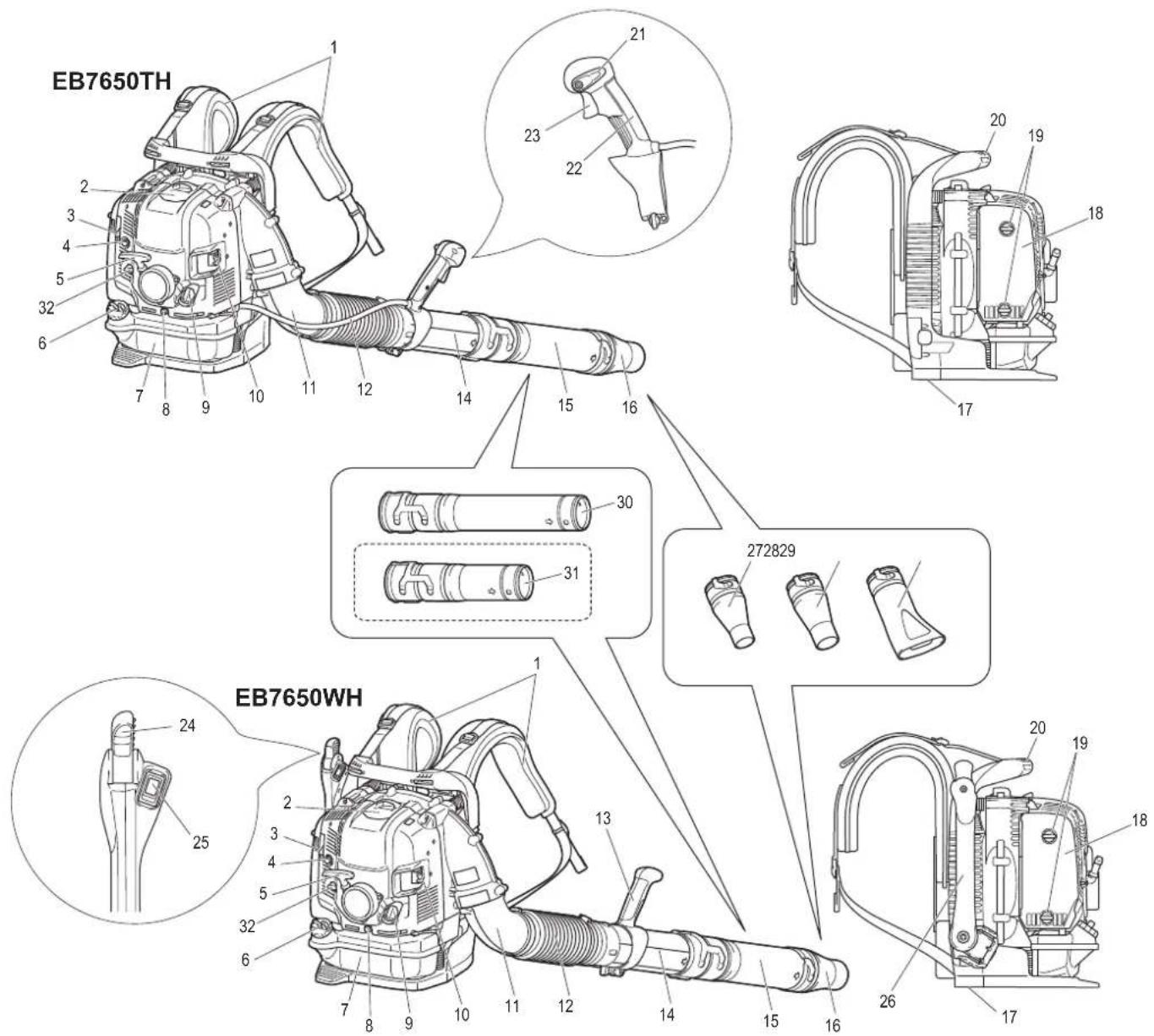
DESIGNATION OF PARTS
text_image
EB7650TH 1 2 3 4 5 32 6 7 8 9 10 11 12 14 15 16 21 23 22 20 19 18 17 30 31 272829 24 25 EB7650WH 1 2 3 4 5 32 6 7 8 9 10 11 12 14 15 16 20 19 18 26 17| 1. Shoulder strap 9. Oil cap 17. Air | inlet net (at the bottom) 25. Stop switch | ||
| 2. Spark plug cover 10. Muffler 18. | Air cleaner cover 26. Control arm | ||
| 3. Choke lever 11. Elbow 19. Bolt | of air cleaner cover) 27. Speed nozzle | ||
| 4. Primer pump 12. Flexible pipe | 20. Carry handle 28. Volume nozzle | ||
| 5. Starter knob | 13. Handle assembly | 21. Stop control lever | 29. Flat nozzle |
| 6. Fuel tank cap | 14. Swivel | 22. Control handle 30. Long pipe | |
| 7. Fuel tank | 15. Pipe (long/short) | 23. Throttle trigger | 31. Short pipe (optional accessory) |
| 8. Oil drain bolt | 16. Nozzle | 24. Throttle lever | 32. Anti icing lever |
- Standard accessories may differ from country to country.
ASSEMBLY INSTRUCTIONS
ASSEMBLY OF BLOWER PIPES
CAUTION:
- Before performing any work on the blower, always stop the engine and pull the spark plug connectors off the spark plug.
Always wear protective gloves! -
Start the blower only after having assembled it completely.
• Always wear protective gloves! -
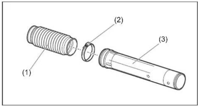
Insert the swivel (3) into the flexible pipe (1) and tighten them with hose band (2).
-
Install the control handle / handle assembly (4) onto the swivel and tighten them with the clamp screw (5).
text_image
(1) (2) (3)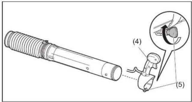
text_image
Technical diagram showing a mechanical component with labeled parts (4) and (5), including a magnified inset of a device detail.3. For tube throttle model
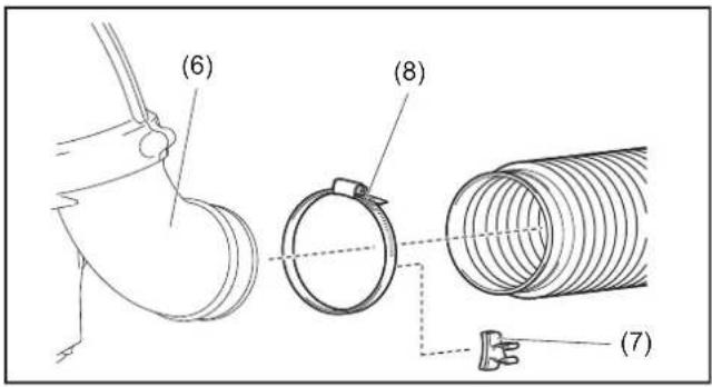
Insert the flexible pipe to elbow (6) of the blower.
Attach the cable holder (7) between the hose band (8) and the elbow.
Tighten the cable holder, flexible pipe and elbow with the hose band.
Set the control cable (9) onto the cable holder (7).
For hip throttle model
Insert the flexible pipe to elbow (6) of the blower.
Tighten the flexible pipe and elbow with the hose band (8).
text_image
(6) (8) (7)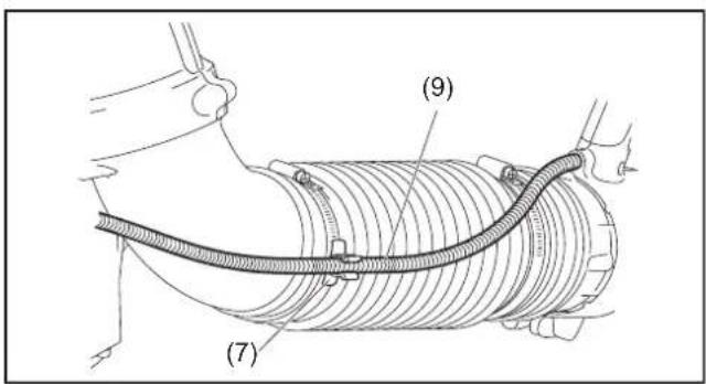
text_image
(7) (9)-
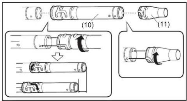
Attach the long/short pipe (10) with the swivel. Turn the long/short pipe clockwise to lock it into place.
Then attach the blower nozzle (11) with the long/short pipe. Turn the blower nozzle clockwise to lock it into place. -
Make sure all clamps are tight.
text_image
(10) (11)BEFORE STARTING THE ENGINE
1. Checking and Refilling Engine Oil
1) Perform the following procedure, with the engine cooled down. Otherwise skin burn may result.
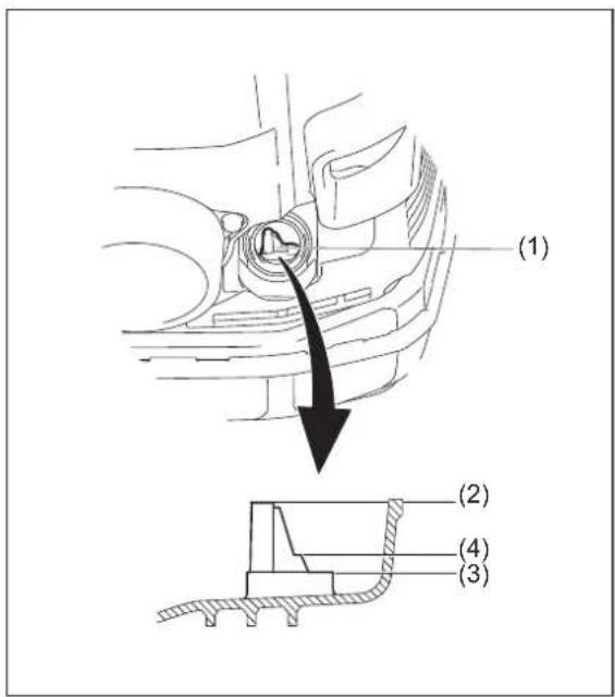
- Inspection: Put the blower on a flat surface and remove the oil cap.
Check the oil gauge (1). Make sure that the oil level is within the upper (2) and lower (3) limit marks. If the oil is not up to the 100 ml level (4), fill up with new oil.
- Filling oil: Put the blower on a flat surface and remove the oil cap.
Fill the oil up to the upper limit of the oil level gauge.
2) On average, engine oil needs to be added after every 20 hours of operation (every 10 – 15 refuellings).
3) Change the oil whenever it becomes dirty or significantly changes color. (Refer to "Replacement of engine oil" for the oil change procedure and frequency.)
text_image
(1) (2) (3) (4)Recommended oil: Makita genuine oil or SAE10W-30 oil of API type SF grade or better (4 stroke motor oil for automobiles)
Oil capacity: Approximately 0.22 L (220 ml)
NOTE:
- If the blower is not stored in an upright position, the oil may flow from the level gauge into the engine and give a false reading when checking the oil level. This may result in inadvertently overfilling whenever adding engine oil. Always store the blower in an upright position.
- If the engine oil is exceeded, the oil may spill from the breather of the air cleaner and make surrounding parts dirty, or white smoke may appear due to burning excessive oil.
Replacement of Oil "Oil cap"
- Remove dust or dirt near the oil refill port, and detach the oil cap.
- Keep the detached oil cap free of sand or dust. Otherwise, any sand or dust adhering to the oil cap may cause irregular oil circulation or wear on the engine parts, which will result in troubles.
After refilling oil
• Wipe with a rag any spilled oil.
2. Fuel supply

WARNING:
- When refuelling the unit, be sure to observe the following instructions to prevent ignition or fire or personal injury:
– Fuel supply must be made in a place free of fire. Never bring the fire (smoking, etc.) near the place of fuel supply.
- Stop the engine and allow the engine to cool down before refuelling.
- Refuel on flat surface. Do not refuel on unstable or bad ventilated place.
- Refuel in good light and visibility.
- Refuel at open clear place.
- Open the fuel tank cap slowly. The fuel may be spilled out by internal pressure.
- Take care not to spill the fuel. Any spilled fuel must be wiped clean.
- Carry out fuel supply in a well-ventilated place.
- Handle the fuel with care.
- Fuel sticking to the skin or entering an eye may cause allergies or irritation. When any physical abnormality is detected, consult the medical specialist immediately.
• DO NOT put oil in the fuel tank.
STORAGE PERIOD OF FUEL
Fuel should be used within a period of 4 weeks, even if it is kept in a special container in a well-ventilated and shaded area.
Otherwise, fuel may deteriorate in one day.
Storage of machine and refill tank
- Keep the machine and tank at a cool place free from direct sunshine.
- Never keep the fuel in a car.
FUEL
The engine is a four-stroke engine. Be sure to use an automobile gasoline (regular gasoline or premium gasoline).
Points for Fuel
- Never use a gasoline mixture which contains engine oil. Otherwise, it will cause excessive carbon accumulation or mechanical troubles.
- Use of deteriorated oil will cause irregular start-up.
When refuelling, stop the engine and wait for the engine to cool down.
REFUELLING METHOD
- Loosen the tank cap a little to release the tank pressure.
- Detach the tank cap, and refuel, discharging air by tilting the fuel tank so that the refuel port will be oriented upward. DO NOT fill fuel up to the top of the tank.
• After refuelling, securely tighten the tank cap. - If there is any flaw or damage on the tank cap, replace it.
- The tank cap wears out in course of time. Replace it every two to three years.
• DO NOT put fuel in the oil fill port.
OPERATION
1. Starting
WARNING:
- Never attempt engine start in a place where the fuel has been supplied.
- It may cause ignition or fire. When starting the engine, keep a distance of at least 3 m.
- Exhaust gas from the engine is toxic. Do not operate the engine in a poorly-ventilated place, such as in a tunnel, building, etc.
- Operating the engine in the poorly-ventilated place may cause poisoning by exhaust gas.
- In case of detection of any abnormality in sound, odor, vibration after starting, stop the engine immediately and carry out inspection.
- If the engine is operated without attending such abnormality, an accident may occur.
- Do not touch hot engine cover. Otherwise skin burn may result.
- Make sure that there are no fuel leakage before starting the engine.
- Make sure that the engine stops when the stop switch is set to "O" position.
1) When the engine is cold or after refuelling (cold start)
(1) Put the blower on a flat surface.
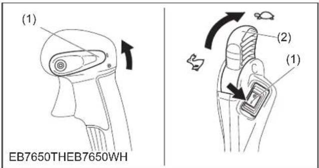
(2) For tube throttle model
Set the stop control lever (1) to "I" position.
(2) For hip throttle model
Set the stop switch (1) to "l" position.
And make sure that the throttle lever (2) is set to low speed position.
(3) Continue to push the primer pump (3) until fuel comes into the primer pump.
- In general, fuel comes into the carburetor by 7 to 10 pushes.
- Even the primer pump is pushed excessively, an excess of gasoline returns to the fuel tank.
(4) Lift the choke lever (4) to the closed position.
(5) Stump the pedal with your right foot, and hold the top of the unit cover with left hand to prevent the engine from moving.
(6) Pull out slowly the starter handle till feeling compression. Then pull it strongly.
- Never pull the rope to the full extension.
- Return the starter knob gently into the housing. Otherwise released starter knob may hit your body or it may not rewind appropriately.
(7) When the engine starts, down the choke lever to open position.
- Open the choke lever fully when checking the engine operation.
- In cold temperature or when the engine is not warm enough, never open the choke lever suddenly. Otherwise, the engine may stop.
(8) Continue warm-up operation for 2 to 3 minutes.
(9) Warm-up is complete when quick engine acceleration from low rpm to full throttle is felt.
text_image
(1) EB7650THEB7650WH (2) (1)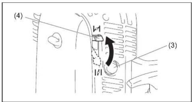
text_image
(4) (3)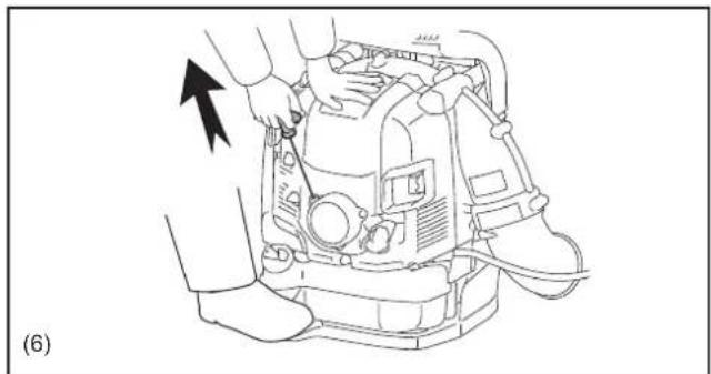
natural_image
Line drawing of a mechanical device with an arrow indicating a process or operation (no text or symbols present)
text_image
Diagram showing a hand operating a valve mechanism with labeled parts and directional arrow indicating rotation or movement.NOTE:
- The engine may be damaged if the choke lever is moved further beyond the "CLOSE" position.
- If the engine fires and stops, return this lever to the "OPEN" position and pull the starter handle several times to start the engine again.
- If the operator keeps pulling the starter handle several times with the choke lever left in the "CLOSE" position, the engine may be difficult to start because of flooding of the fuel.
- In case of flooding of the fuel, remove the spark plug and pull the handle several times rapidly to discharge any excess fuel. Dry the spark plug electrode.
- When the throttle valve (1) does not return to a position in contact with the idling adjusting screw (2) even if the throttle lever is set to the low speed, correct the control cable (3) catching state to ensure proper return of the valve.
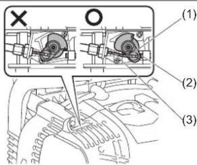
text_image
Technical diagram showing mechanical assembly with labeled parts (1), (2), and (3) indicating different components or states.2) When the engine is warm (warm start)
(1) Put the engine on a flat surface.
(2) Push the primer pump several times.
(3) Make sure that the choke lever is open.
(4) Stump the pedal with your right foot, and hold the top of the unit with left hand to prevent the engine from moving.
(5) Pull slowly the starter handle till feeling compression. Then pull it strongly.
(6) When the engine is difficult to start, open the throttle valve by about 1/3.
2. Stopping
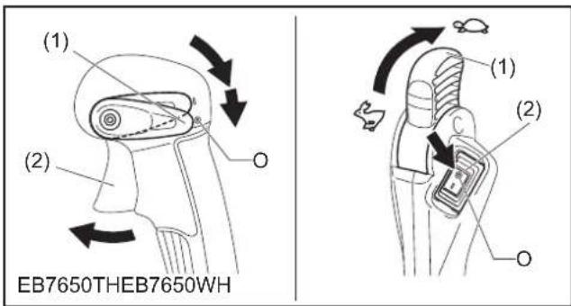
For tube throttle model
Release the throttle trigger (2) and then set the stop control lever (1) to "O" position.
For hip throttle model
Set the throttle lever (1) to the low speed position to reduce the engine speed. Then set the stop switch (2) to "O" position.
text_image
(1) (2) EB7650THEB7650WH (1) (2) OADJUSTMENT OF IDLING
CAUTION:
- The carburetor is factory adjusted. Never adjust other than idling adjusting. For other adjustments, ask Makita authorized service center.
Checkup of low-speed rotation
Set the low-speed rotation to 2,800 rpm (/min).
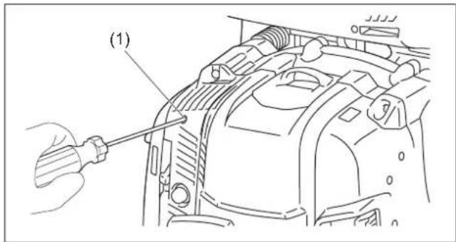
- If it is necessary to change the rotation speed, regulate the idling adjusting screw (1), with Phillips screwdriver.
- Turn the adjusting screw to the right, and the engine speed will increase. Turn the adjusting screw to the left, and the engine speed will drop.
text_image
(1)PREVENTION FROM CARBURETOR ICING
CAUTION:
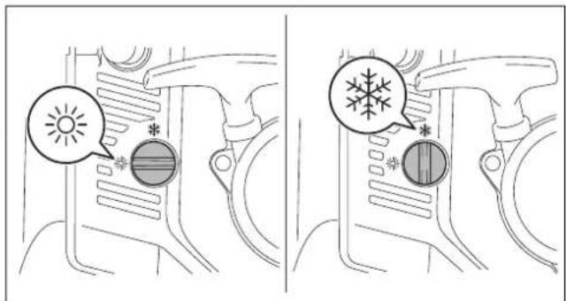
- When environmental temperature is higher than 10^ C, always return the lever to normal (sun mark) setting. Otherwise the engine may be damaged by overheating.
When the environmental temperature is low and humidity is high, water vapor may freeze inside the carburetor and the engine drives unsteadily (carburetor icing). Change the setting of the anti icing lever as follows if necessary.
- Environment temperature is higher than 10^ : Turn the lever to normal position (sun mark).
- Environment temperature is equal or lower than 10^ : Turn the lever to anti-icing position (snow mark).
text_image
Diagram showing car air condition indicators with sun and snow symbols, likely illustrating weather or environmental conditions.OPERATION METHOD
1. Adjusting Shoulder strap
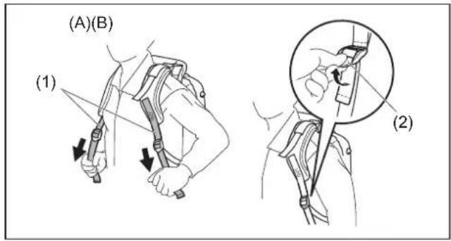
Adjust the shoulder strap (1) to a length that is comfortable to work while carrying the blower. To fasten (A) the strap, pull the end of the strap downwards. To loosen (B) the strap, pull up the end of the fastener (2).
text_image
(A)(B) (1) (2)Pull the stabilizer strap (3) until there are no space left between your back and the blower housing. To fasten (C) the strap, pull the end of the strap downwards. To loosen (D) the strap, pull up the end of the fastener (4).
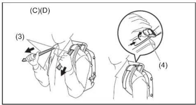
text_image
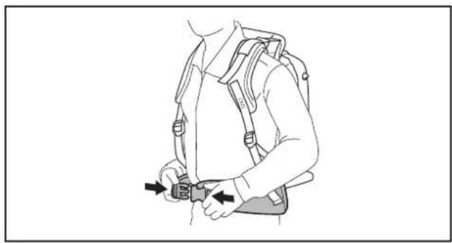
(C)(D) (3) (4)The hip belt (optional accessory) enables the operator to carry the tool more stably.
natural_image
Line drawing of a person wearing a backpack and belt, holding a belt buckle (no text or symbols)2. Adjusting the control lever
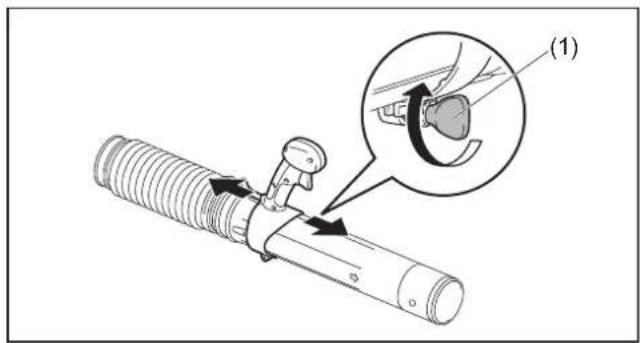
For tube throttle model
Move the control handle along the swivel pipe to the most comfortable position. Then tighten the control handle with the screw (1).
text_image
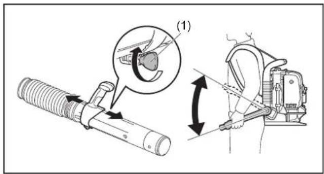
Technical diagram showing a mechanical assembly with labeled component (1) and an inset view of a gear mechanism.For hip throttle model
Move the handle assemble along the swivel to the most comfortable position. Then tighten the handle with the screw (1). Adjust the angle of the control arm for comfortable operation.
text_image
Technical diagram showing mechanical assembly with labeled parts and motion arrows, including a magnified inset of a component.3. Blower Operation
1) While operating the blower, adjust the throttle trigger / throttle lever so that the wind force is appropriate for the work location and conditions.
2) Adjusting engine speed.
For tube throttle model
Engine speed increases by pulling the throttle trigger (1). To decrease the engine speed, loosen the throttle trigger.
Adjusting engine speed with the cruise control function:
The cruise control function allows the operator to maintain a constant engine speed without operating the trigger lever.
To increase the engine speed, turn the stop control lever (2) to high speed.
To decrease the engine speed, turn the stop control lever to low speed.
For hip throttle model
To increase the engine speed, turn the throttle lever (1) to high speed.
To decrease the engine speed, turn the throttle lever to low speed.
natural_image
Line drawing of a person wearing a backpack and holding a long, handheld device (no text or symbols)
text_image
(2) (1) EB7650THEB7650WH (1)TRANSPORTING AND STORING THE BLOWER

CAUTION:
- When transporting the blower, be sure to stop the engine.
Do not sit or stand on the blower nor put an heavy object on it. It may damage the tool.
Maintain the blower in an upright position whenever transporting or storing.
Transporting or storing in a position that is not upright may cause oil to spill inside the blower engine. This may result in oil leaks and white smoke from burning oil, and the air cleaner may become dirty with oil.
Do not drag the blower when transporting. Otherwise the blower housing or air inlet net may be damaged, and it may cause rust.
* On the air inlet net there are ground contacts (1) which discharges electrostatic to the ground.
natural_image
Technical line drawing of a mechanical device with hoses and a cylindrical component (no text or symbols)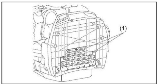
text_image
(1)INSPECTION AND MAINTENANCE
CAUTION:
- Before inspection and maintenance, stop the engine and allow it to cool down. Remove the spark plug and plug cap.
- Otherwise the operator may suffer burn or serious injury due to an accidental start-up.
- After inspection and maintenance, make sure that all parts are assembled. Then, proceed to operation.
1. Replacement of engine oil
Deteriorated engine oil will shorten the life of the sliding and rotating parts to a great extent. Be sure to check the period and quantity of replacement.
CAUTION:
- The engine main unit and engine oil still remain hot just after the engine is stopped. In replacement of oil, make sure that the engine main unit and engine oil are sufficiently cooled down. Otherwise, there may remain a risk of scald. Allow sufficient time after stopping engine for the engine oil to return to the oil tank to ensure accurate reading of the oil level indicator.
- If the oil filled above the limit, it may become dirty or may catch fire with white smoke.
Interval of replacement: After first 20 operating hours, followed by every 50 operating hours
Recommended oil: SAE10W-30 oil, API Classification SF Class or higher (4-stroke engine oil for automobile)
Oil Change Procedure
Please follow these steps when changing the oil:
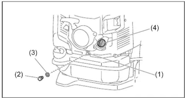
(1) Set the blower down on a level surface.
(2) Put a waste oil container under the drainage hole (1) to catch the oil as it drains out. The container should have a capacity of at least 220 ml to be able to catch all of the oil.
(3) Loosen the oil drain bolt (2) to let the oil drain out. Be careful not to allow oil to get on the fuel tank or other parts.
CAUTION:
- Be careful not to lose the gasket (aluminum washer) (3). Put the oil drain bolt (2) in a location where it will not accumulate dirt.
(4) Remove the oil cap (4). (Removing the oil cap (4) allows the oil to drain easily.)
CAUTION:
- Be sure to set the oil cap (4) down in a location where it will not accumulate dirt.
(5) As the level of the oil being drained decreases, tilt the blower over on to the side with the drain so that the oil will completely drain out.
(6) After the oil has completely drained out, tighten the oil drain bolt (2) securely. If the bolt is not tightly fastened, this may result in an oil leak.
CAUTION:
- Do not forget to put the gasket (aluminum washer) (3) back on when reattaching the drain plug.
(7) Adding oil during the oil change procedure is performed in the same manner as the separately explained procedure for adding oil whenever the level is insufficient. Always add oil by filling from the opening under the oil cap.
(Specified oil level: Approximately 220 ml)
(8) After filling with oil, tighten the oil cap (4) securely to prevent oil leaks.
text_image
(1) (2) (3) (4)Points in replacement of engine oil
- Never discard replaced engine oil in garbage, earth or sewage ditch. Disposal of oil is regulated by law. In disposal, always follow the relevant laws and regulations. For any points remaining unknown, contact Authorized Service Agent.
- Oil will deteriorate even when it is kept unused. Perform inspection and replacement at regular intervals (replace with new oil every 6 months).
2. Cleaning of air cleaner

WARNING: INFLAMMABLES STRICTLY PROHIBITED
Interval of Cleaning and Inspection: Daily (every 10 operating hours)
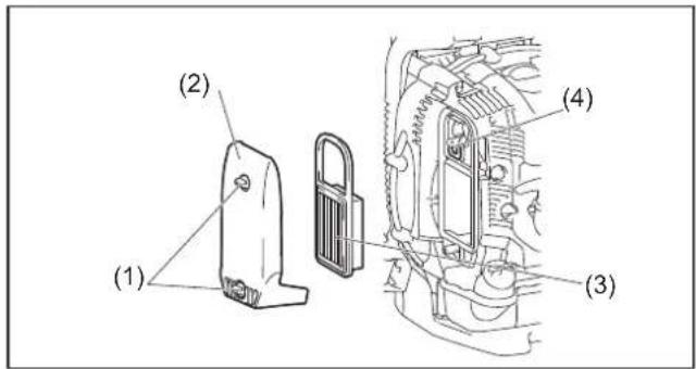
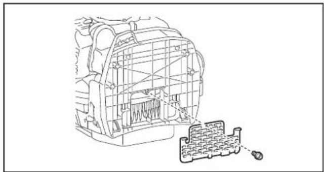
(1) Loosen the bolts (1).
(2) Remove the air cleaner cover (2).
(3) Remove the element (3) and clean off any dirt from the element with the brush.
Note:
- The element is a dry type and should not get wet. Never wash with water.
(4) Replace the element with a new one if it is damaged or very dirty.
(5) Wipe off any oil that has come in to contact with the breather (4) with a rag or cloth.
(6) Install the element in the air cleaner case.
(7) Attach the air cleaner cover and tighten the knob bolt.
NOTICE:
- Clean the element several times a day, if excessive dust adheres to it.
- If operation continues with the element remaining not cleared of oil, oil in the air cleaner may fall outside, resulting in oil contamination.
3. Checking the spark plug
CAUTION:
- Do not touch the spark plug while the engine is running. Otherwise electrical shock may result.
- Set the stop control lever/stop switch to OFF "O" position.
- Check the spark plug cord regularly. If it is damaged or torn, replace it. Otherwise electrical shock may result.
- When removing the spark plug, clean the spark plug and cylinder head first, so that no dirt, sand, etc will enter the cylinder.
- Remove the spark plug after the engine has cooled down in order to avoid damaging the threaded hole in the cylinder.
- Install the spark plug properly into the threaded hole. If installed at an angle, the threaded hole in the cylinder will get damaged.
(1) Opening/closing the plug cover
To open (A) the plug cover (1), lift it and make a half turn of it. To close (B) the plug cover, make a half turn of it, and press around the dented part.
(2) Removing the spark plug
Use an attached box wrench to remove or install the spark plug.
(3) Checking the spark plug
The clearance between two electrodes of spark plug is 0.7 to 0.8 mm. Adjust to the correct clearance when it is too wide or too narrow. Clean thoroughly or replace the spark plug if it has accumulated carbon or contaminated.
(4) Replacing the spark plug
For replacement, use NGK-CMR6A.
text_image
(1) (2) (3) (4)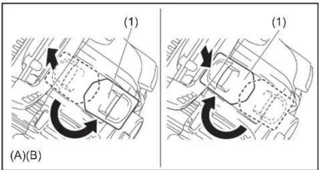
text_image
(1) (A)(B) (1)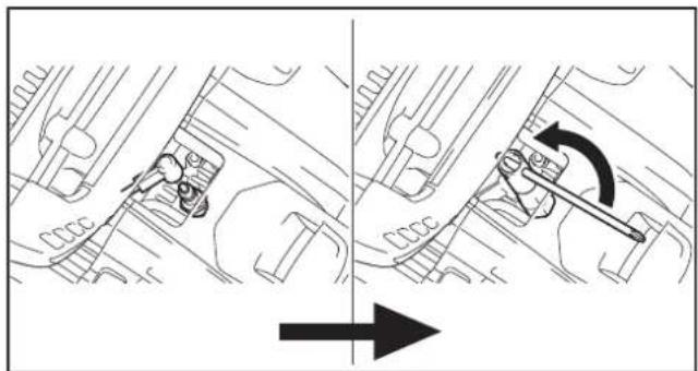
natural_image
Technical diagram showing mechanical assembly with directional arrow (no text or symbols)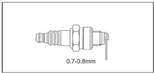
text_image
0.7-0.8mm4. Cleaning the fuel filter
- Clogged fuel filter may cause difficulty of start-up or failure of engine speed increase.
- Check the fuel filter regularly as follows:
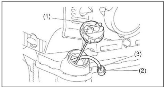
(1) Remove the fuel tank cap (1), drain the fuel to empty the tank. Check the tank inside for any foreign materials. If any, wipe clean such materials.
(2) Pull out the fuel filter (2) with wire through the oil filling port.
(3) If the fuel filter surface is contaminated, clean it with gasoline. The gasoline used for the cleaning must be disposed of according to the method specified by each local authority. Excessively contaminated filter must be replaced.
(4) After checking, cleaning or replacing, insert the fuel filter into the fuel pipe and fix it by the hose clamp (3). Reset the fuel filter in the fuel tank and tighten firmly the fuel tank cap.
• Make sure there is no damage on the fuel tank.
5. Inspection of bolts, nuts and screws
• Retighten loose bolts, nuts, etc.
- Check for fuel and oil leakage.
- Replace damaged parts with new ones for safety operation.
6. Cleaning of parts
- Keep engine clean by wiping down with a cloth rag.
- Keep the cylinder fins free of dust or dirt. Dust or dirt adhering to the fins will cause seizure.
- Blowing air is taken in from the air inlet vent and the air inlet net (1). When airflow drops down during operation, stop engine and inspect the air inlet vent and the air inlet net for any blockages. Clean it if necessary.
- Check the air inlet net at the bottom. Remove the screw and the air inlet net. Check if there are any blockages. Clean it if necessary.
- Such a blockage may cause overheat and damage the engine.
WARNING:
- Never use the blower without the net of the blower. Before each use, check that the net is attached in place and is free from any damage.
7. Replacement of gaskets and packings
Replace gaskets and packings if the engine is disassembled. Any maintenance of adjustment work that is not included and described in this manual is only to be performed by Authorized Service Agent.
text_image
(1) (2) (3)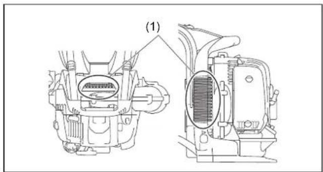
text_image
(1)
natural_image
Technical line drawing of a mechanical component with internal structure and a separate inset showing a connector (no text or symbols)STORAGE
WARNING:
- When draining the fuel, stop the engine and wait for the engine to cool down. - Failure to do so may cause burns or fire.
CAUTION:
- When you store the machine for a long time, drain all fuel from the fuel tank and carburetor, and keep it at a dry and clean place.
Drain fuel from the fuel tank and carburetor according to the following procedure:
(1) Remove the fuel tank cap, and drain fuel completely. If there is any foreign materials remaining in the fuel tank, remove it completely.
(2) Pull out the fuel filter from the refill port using a wire.
(3) Push the primer pump until fuel is drained from there, and drain fuel coming into the fuel tank.
(4) Reset the filter to the fuel tank, and securely tighten the fuel tank cap.
(5) Then, continue to operate the engine until it stops.
(6) Remove the spark plug, and drip several drops of engine oil through the spark plug hole.
(7) Gently pull the starter handle so that engine oil will spread over the engine, and attach the spark plug.
(8) Keep the machine with its handle upside.
(9) Keep the drained fuel in a special container in a well-ventilated shade.
Fault location
| Fault System Observation | Cause | ||
| Engine not starting or with difficulty | Ignition system Ignition spark | O.K. Fault in fuel supply | or compression system, mechanical defect |
| No ignition spark STOP-switch | witch operated, wiring fault or short circuit, spark plug or connector defective, ignition module faulty | ||
| Fuel supply Fuel tank filled | Incorrect choke position, carburetor defective, fuel supply line bent or blocked, fuel dirty. | ||
| Compression No compression when pulled over | Cylinder bottom gasket defective, crankshaft seals damaged, cylinder or piston rings defective or improper sealing of spark plug | ||
| Mechanical fault Starter not engaging Broken starter spring, broken parts inside of the engine | |||
| Warm start problems Tank filled ignition spark existing | Carburetor contaminated, have it cleaned | ||
| Engine starts but dies | Fuel supply | Tank filled | Incorrect idling adjustment, carburetor contaminated |
| Fuel tank vent defective, fuel supply line interrupted, cable or STOP-switch faulty | |||
| Insufficient performance | Several systems may simultaneously be affected | Engine idling poor | Air filter contaminated, carburetor contaminated, muffler clogged, exhaust duct in the cylinder clogged |
| Item\Operating time | Before operation | After lubrication | Daily (10h) | 30h | 50h | 200h | Shutdown/rest | Corresponding Page | |
| Engine oil | Inspect/clean | ○ | 10 | ||||||
| Replace | ^1 | 17 | |||||||
| Tightening parts (bolt, nut) | Inspect | ○ | 19 | ||||||
| Fuel tank | Clean/inspect | ○ | — | ||||||
| Drain fuel | ^3 | 19 | |||||||
| Throttle trigger/throttle lever | Check function | ○ | — | ||||||
| Stop control lever/stop switch | Check function | ○ | 13 | ||||||
| Low-speed rotation Inspect/adjust | ○ | 14 | |||||||
| Air cleaner | Clean | ○ | 18 | ||||||
| Ignition plug / plug cord | Inspect | ○ | 18 | ||||||
| Cooling air duct | Clean/inspect | ○ | 19 | ||||||
| Fuel pipe | Inspect | ○ | 19 | ||||||
| Replace | ©^12 | — | |||||||
| Fuel filter | Clean/replace | ○ | 19 | ||||||
| Clearance between air intake valve and air discharge valve | Adjust | ©^12 | — | ||||||
| Oil tube | Inspect | ©^12 | — | ||||||
| Engine overhaul | ©^12 | — | |||||||
| Carburetor | Drain fuel | ^3 | 19 | ||||||
*1 Perform initial replacement after 20h operation.
*2 For the 200 operating hour inspection, request Authorized Service Agent or a machine shop.
*3 After emptying the fuel tank, continue to run the engine and drain fuel in the carburetor.
TROUBLESHOOTING
Before making a request for repairs, check a trouble for yourself. If any abnormality is found, control your machine according to the description of this manual. Never tamper or dismount any part contrary to the description. For repairs, contact Authorized Service Agent or local dealership.
| State of abnormality Probable cause (malfunction) Remedy | ||
| Engine does not start | Failure to operate primer pump Push 7 to 10 times. | |
| Low pulling speed of starter rope Pull strongly. | ||
| Lack of fuel Feed fuel. | ||
| Clogged fuel filter Clean | ||
| Bent fuel tube Straighten fuel tube | ||
| Deteriorated fuel Deteriorated fuel makes starting more difficult.Replace with new one. (Recommended replacement: 1 month) | ||
| Excessive suction of fuel Set throttle lever from medium speed to high speed, and pull starter handle until engine starts.If engine will not start still, remove spark plug, make electrode dry, and reassemble them as they originally are. Then, start as specified. | ||
| Detached plug cap Attach securely | ||
| Contaminated spark plug Clean | ||
| Abnormal clearance of spark plug Adjust clearance | ||
| Other abnormality of spark plug Replace | ||
| Abnormal carburetor Make request for inspection and maintenance. | ||
| Cannot pull the starter knob | Make request for inspection and maintenance. | |
| Abnormal drive system | Make request for inspection and maintenance. | |
| Engine stops soonEngine speed does not increase | Insufficient warm-up | Perform warm-up operation |
| Choke lever is set to “CLOSE” although engine is warmed up | Set to “OPEN” | |
| Clogged fuel filter Clean | ||
| Contaminated or clogged air cleaner | Clean | |
| Abnormal carburetor Make request for inspection and maintenance. | ||
| Abnormal drive system | Make request for inspection and maintenance. | |
| Detached throttle wire | Attach securely | |
| Engine does not stop.↓Run engine at idling, and set choke lever to “CLOSE”. | Detached connector | Attach securely |
| Abnormal electric system | Make request for inspection and maintenance. | |
When the engine does not start after warm-up operation:
If there is no abnormality found for the check items, open the throttle by about 1/3 and start the engine.
Français
natural_image
Black-and-white illustration of wine bottles crossed out with a diagonal line, no text or symbols present(2)

natural_image
Illustration of two types of headphones: a hand holding a small object and a black headset (no text or symbols)(3)
natural_image
Illustration of a person wearing protective gear, hand-in-hand, and boot (no text or symbols)(4)
text_image
360° 15 mnatural_image
Line drawing of a mechanical device with hands and a black arrow indicating a component (no text or symbols)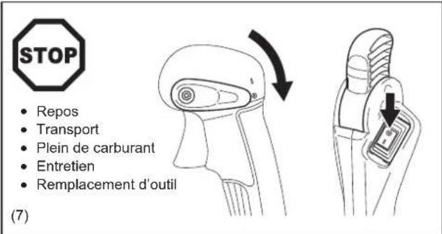
natural_image
Simple black square with a white cross symbol in the center (no text or numbers)(12)
text_image
Technical diagram showing a mechanical component with labeled parts (4) and (5), including a magnified inset of the device's internal structure.text_image
(6) (8) (7)
text_image
(7) (9)text_image
(10) (11)AVANT DE DÉMARRER LE MOTEUR
natural_image
Line drawing of a person operating a mechanical device with a black arrow indicating the direction (no text or symbols present)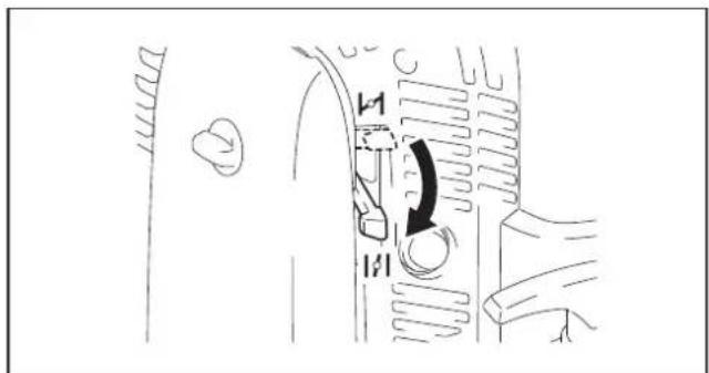
text_image
Diagram showing a mechanical component with labeled parts and directional arrow indicating rotation or movement.NOTE :
text_image
Technical diagram showing mechanical assembly with labeled parts (1), (2), and (3) indicating different components or states.text_image
Diagram showing car interior components with sun and snow icons, labeled with asterisks and symbolsMODE OPÉRATOIRE
text_image
(A)(B) (1) (2)text_image
(C)(D) (3) (4)natural_image
Line drawing of a person wearing a backpack and belt buckle, holding a belt buckle (no text or symbols)text_image
Technical diagram showing a mechanical assembly with labeled component (1) and an inset magnified view of the mechanism.text_image
Technical diagram illustrating a mechanical assembly with labeled parts and directional arrows indicating motion or force.natural_image
Line drawing of a person wearing a backpack and holding a long, handheld device (no text or symbols)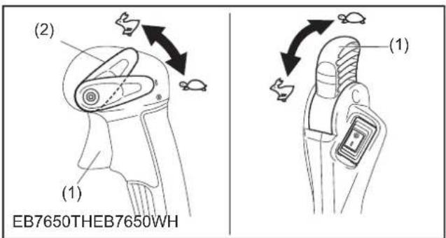
text_image
(2) (1) EB7650THEB7650WH (1)TRANSPORT ET REMISAGE DU SOUFFLEUR
ATTENTION :
natural_image
Technical line drawing of a mechanical device with hoses and a long cylindrical component (no text or symbols)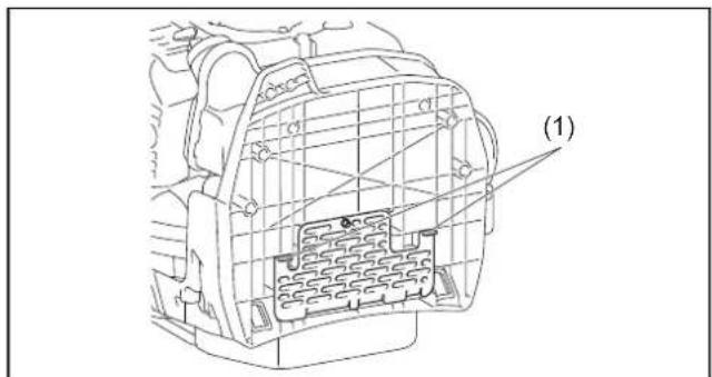
text_image
(1)INSPECTION ET ENTRETIEN
ATTENTION :
text_image
(1) (A)(B) (1)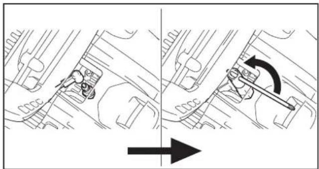
natural_image
Mechanical assembly diagram showing two stages of a tool interacting with a vehicle (no text or labels)
text_image
0.7-0.8mmnatural_image
Technical line drawing of a mechanical component with internal grid structure and a separate inset showing a connector (no text or symbols)REMISAGE
⚠ AVERTISSEMENT :
natural_image
Illustration of a wine bottle crossed with a quill pen, accompanied by small bottles and a small object (no text or symbols)
natural_image
Two black-and-white illustrations: a hand holding a device and a pair of headphones (no text or symbols)
natural_image
Illustration of a worker wearing protective gear, gloves, and a warning sign (no text or symbols on main subjects)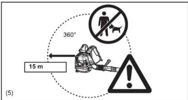
text_image
360° 15 m (5)natural_image
Line drawing of a mechanical device with hands operating it, showing internal components and a black arrow indicating direction (no text or symbols)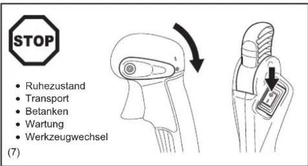
natural_image
Illustration of a firefighter cutting through fire extinguisher with smoke, labeled (11) (no text or symbols on diagram)Erste Hilfe
Michigan Drive, Tongwell, Milton Keynes, Bucks MK15 8JD, England
3-11-8, Sumiyoshi-cho,
Anjo, Aichi, JAPAN
TECHNISCHE DATEN
text_image
Technical diagram showing a mechanical component with labeled parts (4) and (5), including a magnified inset of a device detail.text_image
(6) (8) (7)
text_image
(7) (9)text_image
(10) (11)VOR DEM STARTEN DES MOTORS
natural_image
Line drawing of a person using a mechanical device with an arrow indicating the process (no text or symbols present)
text_image
Diagram showing a hand operating a device with labeled parts and directional arrow indicating rotation or movement.HINWEIS:
text_image
Diagram showing car air condition indicators with sun and snow symbols, likely illustrating weather or environmental conditions.BETRIEBSMETHODE
text_image
(A)(B) (1) (2)text_image
(C)(D) (3) (4)natural_image
Line drawing of a person wearing a backpack and belt, holding a belt buckle (no text or symbols)text_image
Technical diagram showing mechanical assembly with labeled component (1) and directional arrows indicating movement or forcetext_image
Technical diagram showing mechanical assembly and tool path with labeled component (1)natural_image
Line drawing of a person wearing a backpack and holding a long, cylindrical device (no text or symbols)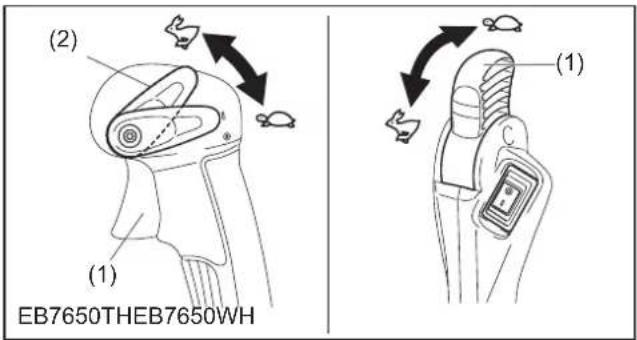
text_image
(2) (1) EB7650THEB7650WH (1)TRANSPORTIEREN UND LAGERN DES BLASGERÄTES

VORSICHT:
natural_image
Technical line drawing of a mechanical device with hoses and tubing (no text or symbols)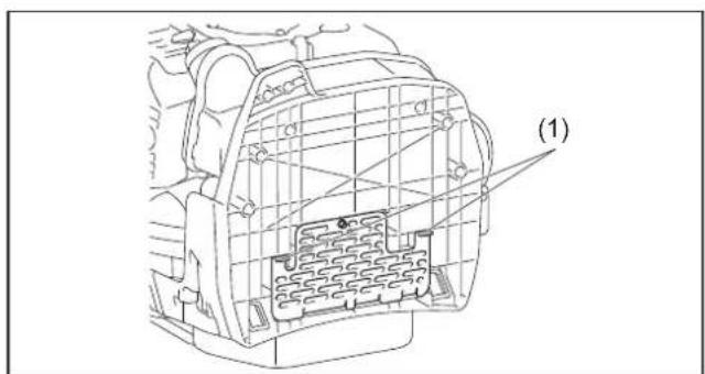
text_image
(1)text_image
(1) (A)(B) (1)
natural_image
Mechanical assembly diagram showing two stages of a tool interacting with a vehicle (no text or symbols present)
text_image
0.7-0.8mmnatural_image
Technical line drawing of a mechanical component with internal structure and a separate connector pin (no text or symbols)LAGERUNG
⚠️ WARNING:
natural_image
Two symbolic icons: a closed book and a triangular warning sign with an exclamation mark (no text or symbols present)(1)

natural_image
Silhouette illustration of a crossed glass bottle and two smaller bottles with scattered pills (no text or symbols)(2)

natural_image
Illustration of two types of headphones: a hand holding a pair of glasses and a pair of headphones (no text or symbols)(3)

natural_image
Illustration of safety symbols including a worker, gloves, a warning sign, and boots (no text or labels)(4)

text_image
360° 15 metrinatural_image
Line drawing of a mechanical device with hands and a black arrow indicating a component (no text or symbols)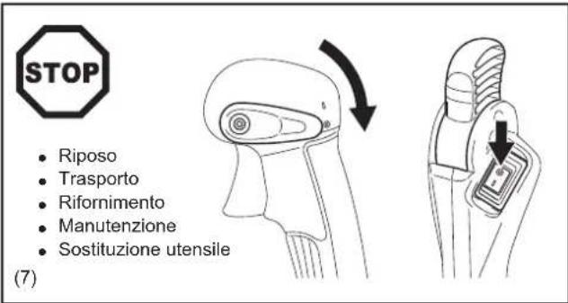
natural_image
Illustration of a firefighter in action with a campfire and smoke, no text or symbols presentPronto soccorso
natural_image
Simple black square with a white cross symbol in the center (no text or numbers)(12)
Michigan Drive, Tongwell, Milton Keynes, Bucks MK15 8JD, England
3-11-8, Sumiyoshi-cho,
Anjo, Aichi, JAPAN
DATI TECNICI
text_image
Technical diagram showing a mechanical component with labeled parts (4) and (5), including a magnified inset of a device detail.text_image
(6) (8) (7)
text_image
(7) (9)text_image
(10) (11)PRIMA DI AVVIARE IL MOTORE
natural_image
Line drawing of a person using a mechanical device with an arrow indicating the process (no text or symbols present)
text_image
Diagram showing a hand operating a device with labeled parts and directional arrow indicating rotation or movement.NOTA:
text_image
Technical diagram showing mechanical assembly with labeled parts (1), (2), and (3) indicating different components or states.text_image
Diagram showing two views of a vehicle's roof structure with sun and snow symbols, one labeled with an asterisk and star.MODO DI UTILIZZO
text_image
(A)(B) (1) (2)text_image
(C)(D) (3) (4)natural_image
Line drawing of a person wearing a backpack and belt, holding a belt buckle (no text or symbols)text_image
Technical diagram showing mechanical assembly with labeled component (1) and directional arrows indicating movement or forcetext_image
Technical diagram showing mechanical assembly with labeled parts and directional arrows indicating motion or forcenatural_image
Line drawing of a person wearing a backpack and holding a long, cylindrical object (no text or symbols)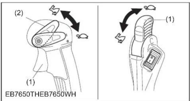
text_image
(2) (1) EB7650THEB7650WH (1)TRASPORTO E IMMAGAZZINAGGIO DEL SOFFIATORE
ATTENZIONE:
natural_image
Technical line drawing of a mechanical device with hoses and a cylindrical shaft (no text or symbols)text_image
(1) (A)(B) (1)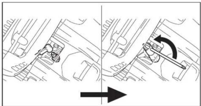
natural_image
Mechanical assembly diagram showing two stages of a tool interacting with a component, with an arrow indicating direction (no text or symbols present)
text_image
0.7-0.8mmnatural_image
Technical line drawing of a mechanical component with internal structure and a separate inset showing a connector (no text or symbols)IMMAGAZZINAGGIO
⚠ AVVERTIMENTO:
natural_image
Warning symbol with exclamation mark inside a triangle (no text or numbers)(1)

natural_image
Illustration of wine bottles and a crossed glass with scattered pills (no text or symbols)(2)


(3)


(4)
text_image
360° 15 meternatural_image
Line drawing of a mechanical device with hands and a black arrow indicating a component (no text or symbols)
natural_image
Diagram showing a device being adjusted to form a tool, with no visible text or symbols.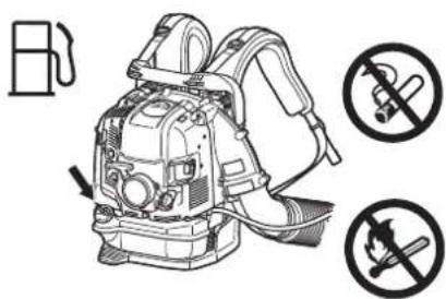
text_image
B No No(8)
text_image
(9) 3 meterBedieningsvoorschriften
natural_image
Illustration of a soldier operating a weapon with a campfire symbol nearby (no text or labels)Eerste hulp
natural_image
Simple black square with a white cross symbol in the center (no text or numbers)(12)
Michigan Drive, Tongwell, Milton Keynes, Bucks MK15 8JD, Engeland
3-11-8, Sumiyoshi-cho,
Anjo, Aichi, JAPAN
TECHNISCHE GEGEVENS
text_image
Technical diagram showing a mechanical component with labeled parts (4) and (5), including a magnified inset of a device detail.text_image
(6) (8) (7)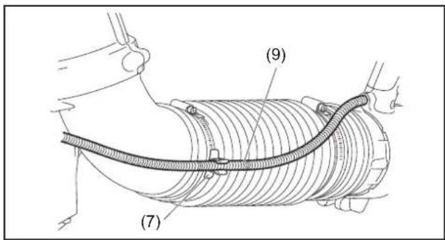
text_image
(7) (9)text_image
(10) (11)VOOR U DE MOTOR GAAT STARTEN
natural_image
Line drawing of a person using a mechanical device with an arrow indicating the process (no text or symbols present)
text_image
Diagram showing a hand operating a device with labeled parts and directional arrow indicating rotation or movement.OPMERKING:
text_image
Technical diagram showing mechanical assembly with labeled parts (1), (2), and (3) indicating different components or states.2) Wanneer de motor warm is (warme start)
text_image
Diagram showing car air condition indicators with sun and snow symbols, likely illustrating weather or environmental conditions.BEDIENINGSMETHODE
text_image
(A)(B) (1) (2)text_image
(C)(D) (3) (4)natural_image
Line drawing of a person wearing a backpack and belt, holding a belt buckle (no text or symbols)2. Afstellen van de bedieningshendel
text_image
Technical diagram showing mechanical assembly with labeled component (1) and magnified detail viewtext_image
Technical diagram showing mechanical assembly with magnified detail and directional arrows indicating motion or forcenatural_image
Line drawing of a person wearing a backpack and holding a long, handheld device (no text or symbols)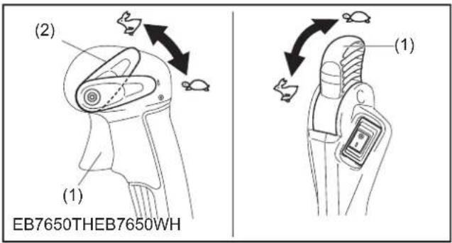
text_image
(2) (1) EB7650THEB7650WH (1)VERVOER EN OPSLAG VAN DE BLAZER

LET OP:
natural_image
Line drawing of a handheld industrial device with hoses and a long cylindrical shaft (no text or symbols)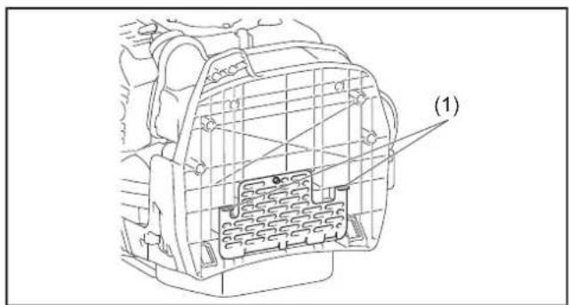
text_image
(1)INSPECTIE EN ONDERHOUD
LET OP:
WAARSCHUWING: BRANDBARE STOFFEN STRENG VERBODEN
text_image
(1) (A)(B) (1)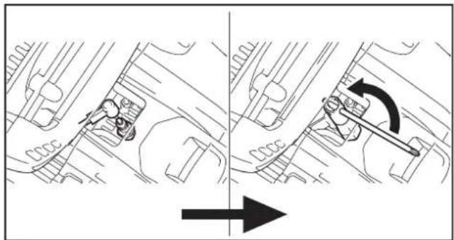
natural_image
Mechanical assembly diagram showing two stages of a tool interacting with a component, with an arrow indicating direction (no text or symbols present)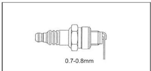
text_image
0.7-0.8mm4. Brandstofffilter schoonmaken
natural_image
Technical line drawing of a mechanical component with internal structure and a separate assembly detail (no text or symbols)OPSLAG APPARATUUR
⚠ WAARSCHUWING:
natural_image
Illustration of wine bottles and a crossed glass with a pen, no text or symbols present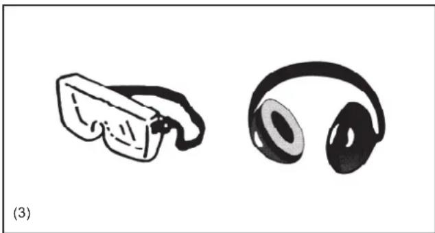
natural_image
Illustration of two types of headphones: a small object and a larger headband, both without any text or symbols.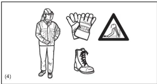
natural_image
Illustration of a worker wearing protective gear, gloves, and a warning sign (no text or symbols on main subjects)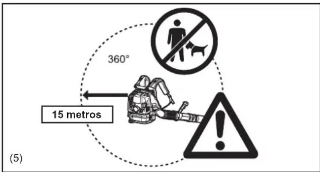
text_image
360° 15 metros (5)natural_image
Line drawing of a mechanical device with hands and a black arrow indicating a component (no text or symbols)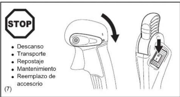
natural_image
Illustration of a soldier in combat gear with a campfire and smoke, no text or symbols presentPrimeros Auxilios
natural_image
Simple black square with a white cross symbol in the center (no text or numbers)(12)
3-11-8, Sumiyoshi-cho,
Anjo, Aichi, JAPÓN
DATOS TÉCNICOS
text_image
Technical diagram showing a mechanical component with labeled parts (4) and (5), including a magnified inset of a biological structure.text_image
(6) (8) (7)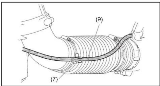
text_image
(7) (9)text_image
(10) (11)ANTES DE ARRANCAR EL MOTOR
natural_image
Line drawing of a person using a mechanical device with an arrow indicating the process (no text or symbols present)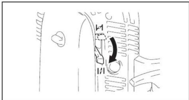
text_image
Diagram showing a hand operating a valve mechanism with labeled parts and directional arrow indicating rotation or movement.NOTA:
text_image
Diagram showing car interior with sun and snow icons, indicating weather conditions for vehicle useMÉTODO DE OPERACIÓN
text_image
(A)(B) (1) (2)text_image
(C)(D) (3) (4)natural_image
Line drawing of a person wearing a backpack and belt, holding a belt buckle (no text or symbols)2. Ajuste de la palanca de control
text_image
Technical diagram showing a mechanical assembly with labeled component (1) and an inset magnified view of the component.text_image
Technical diagram illustrating mechanical assembly with labeled parts and motion arrows, including a magnified inset showing a circular component.natural_image
Line drawing of a person wearing a backpack and holding a long, handheld device (no text or symbols)
text_image
(2) (1) EB7650THEB7650WH (1)TRANSPORTE Y ALMACENAMIENTO DEL SOPLADOR
PRECAUCIÓN:
natural_image
Technical line drawing of a handheld industrial device with hoses and a cylindrical shaft (no text or symbols)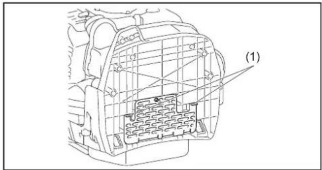
text_image
(1)PRECAUCIÓN:
text_image
(1) (A)(B) (1)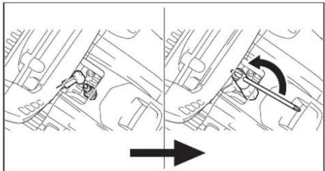
natural_image
Mechanical diagram showing two sequential steps of a device with a directional arrow, no text or symbols present.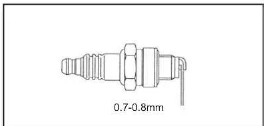
text_image
0.7-0.8mmnatural_image
Technical line drawing of a mechanical component with internal structure and a separate assembly detail (no text or symbols)ALMACENAMIENTO
ADVERTENCIA:
natural_image
Simple line drawing of an open book with no text or symbols visible
natural_image
Warning symbol with exclamation mark inside a triangle (no text or numbers)(1)

natural_image
Illustration of wine bottles and a crossed glass with scattered pills (no text or symbols)(2)


(3)


(4)
text_image
360° 15 metrosnatural_image
Line drawing of a mechanical device with hands and a black arrow indicating a component (no text or symbols)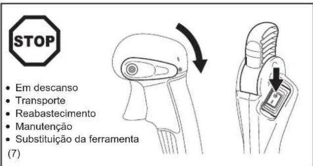
natural_image
Illustration of a soldier in combat gear with a campfire and smoke, no text or symbols presentPrimeiros socorros
natural_image
Simple black square with a white cross symbol in the center (no text or numbers)(12)
Apenas para países europeus
3-11-8, Sumiyoshi-cho,
Anjo, Aichi, JAPÃO
DADOS TÉCNICOS
text_image
Technical diagram showing a mechanical component with labeled parts (4) and (5), including a magnified inset of a device detail.text_image
(6) (8) (7)
text_image
(7) (9)text_image
(10) (11)ANTES DE PÔR O MOTOR A TRABALHAR
natural_image
Line drawing of a person using a mechanical device with an arrow indicating the process (no text or symbols present)
text_image
Diagram showing a hand operating a device with labeled parts and directional arrow indicating rotation or movement.NOTA:
text_image
Technical diagram showing mechanical assembly with labeled parts (1), (2), and (3) indicating different components or states.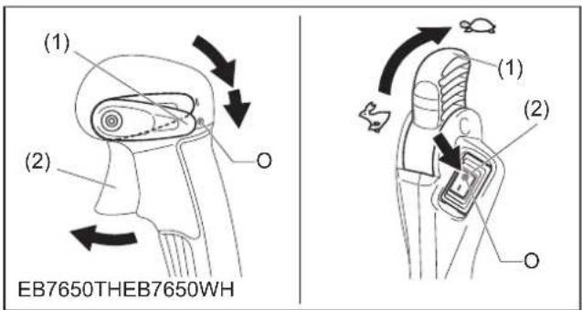
text_image
(1) (2) EB7650THEB7650WH (1) (2) OAJUSTE DO RALENTI
PRECAUÇÃO:
text_image
Diagram showing car air condition indicators with sun and snow symbols, labeled in Chinesetext_image
(A)(B) (1) (2)text_image
(C)(D) (3) (4)natural_image
Line drawing of a person wearing a backpack and belt, holding a belt buckle (no text or symbols)2. Ajustar a alavanca de controlo
text_image
Technical diagram showing mechanical assembly with labeled component (1) and directional arrows indicating movement or force.Para o modelo com acelerador de quadril
text_image
Technical diagram illustrating mechanical assembly and tool path, with labeled parts and directional arrowsnatural_image
Line drawing of a person wearing a backpack and holding a long, cylindrical device (no text or symbols)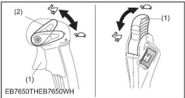
text_image
(2) (1) EB7650THEB7650WH (1)TRANSPORTAR E GUARDAR O SOPRADOR
PRECAUÇÃO:
natural_image
Technical line drawing of a mechanical device with hoses and a cylindrical shaft (no text or symbols)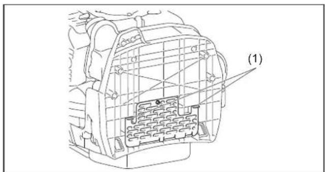
text_image
(1)text_image
(1) (A)(B) (1)
natural_image
Mechanical assembly diagram showing two stages of a tool moving through a gear-like component, with an arrow indicating direction (no text or symbols present)
text_image
0.7-0.8mmnatural_image
Technical line drawing of a mechanical component with internal structure and a separate connector detail (no text or symbols)ARMAZENAMENTO
AVISO:
natural_image
Two symbolic icons: an open book and a triangular warning sign with an exclamation mark (no text or labels)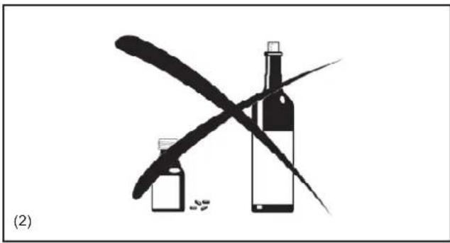
natural_image
Illustration of a wine bottle and its cross-shaped object, no text or symbols present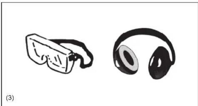
natural_image
Illustration of two types of headphones: a pair of glasses and a pair of headphones (no text or symbols)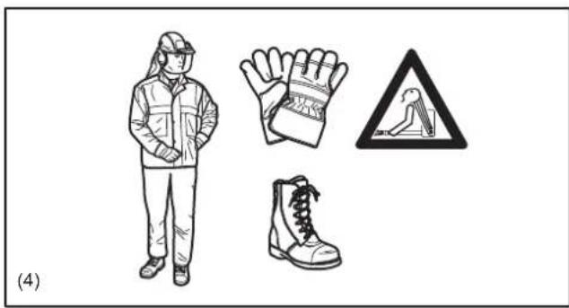
natural_image
Illustration of a worker wearing protective gear, gloves, and a warning sign (no text or symbols on main subjects)
text_image
360° 15 meter (5)natural_image
Line drawing of a mechanical device with hands and a black arrow indicating direction (no text or symbols)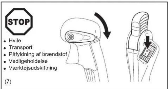
natural_image
Illustration of a soldier in combat gear with a campfire and smoke, no text or symbols presentFørstehjælp
natural_image
Simple black square with a white cross symbol in the center (no text or numbers)(12)
Michigan Drive, Tongwell, Milton Keynes, Bucks MK15 8JD, England
3-11-8, Sumiyoshi-cho,
Anjo, Aichi, JAPAN
TEKNISKE DATA
text_image
Technical diagram showing a mechanical component with labeled parts (4) and (5), including a magnified inset of a tool interacting with a device.text_image
(6) (8) (7)
text_image
(7) (9)text_image
(10) (11)INDEN MOTOREN STARTES
natural_image
Line drawing of a mechanical device with an arrow indicating a process or operation (no text or symbols present)
text_image
Diagram showing a hand operating a valve mechanism with labeled parts and directional arrow indicating rotation or movement.BEMÆRK:
text_image
Technical diagram showing mechanical assembly with labeled parts (1), (2), and (3) indicating different components or states.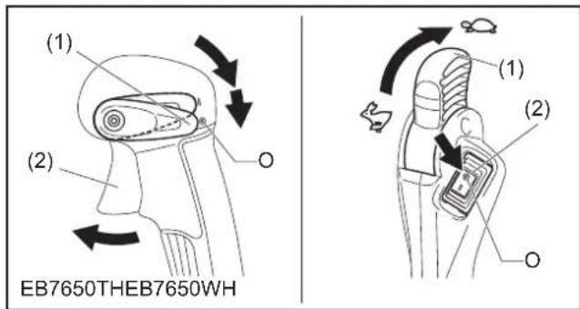
text_image
(1) (2) OB7650THEB7650WH (1) (2) OJUSTERING AF TOMGANG
⚠ FORSIGTIG:
text_image
Diagram showing two scenarios of a car's exhaust air condition, with sun and snow icons indicating environmental impact.ANVENDELSESMETODE
text_image
(A)(B) (1) (2)text_image
(C)(D) (3) (4)natural_image
Line drawing of a person wearing a backpack and belt buckle, holding a belt buckle (no text or symbols)text_image
Technical diagram showing mechanical assembly with labeled component (1) and directional arrows indicating movement or forcetext_image
Technical diagram illustrating mechanical assembly with labeled parts and directional arrows, including a magnified inset showing a circular component.natural_image
Line drawing of a person wearing a backpack and holding a long, handheld device (no text or symbols)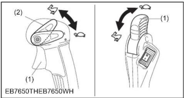
text_image
(2) (1) EB7650THEB7650WH (1)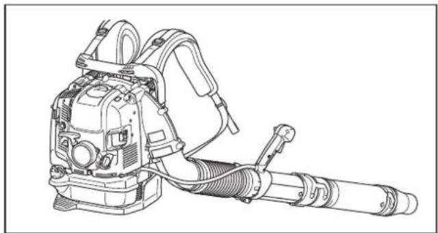
natural_image
Technical line drawing of a mechanical device with hoses and a cylindrical shaft (no text or symbols)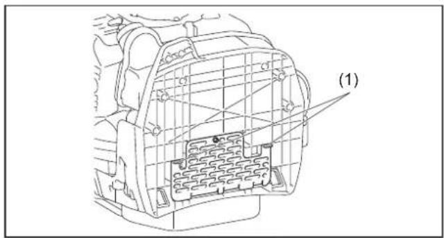
text_image
(1)INSPEKTION OG VEDLIGEHOLDELSE
⚠ FORSIGTIG:
text_image
(1) (A)(B) (1)
natural_image
Diagram showing vehicle dynamics with a directional arrow and rotation arrow (no text or symbols)
text_image
0.7-0.8mmnatural_image
Technical line drawing of a mechanical component with internal structure and a separate connector detail (no text or symbols)OPBEVARING
ADVARSEL:
natural_image
Illustration of wine bottles and a crossed glass with scattered pills (no text or symbols)(2)

natural_image
Illustration of two types of headphones: a hand holding a pair of glasses and a black-framed headset (no text or symbols)(3)
(4)
natural_image
Line drawing of a mechanical device with hands operating it, showing internal components and a black arrow indicating direction (no text or symbols)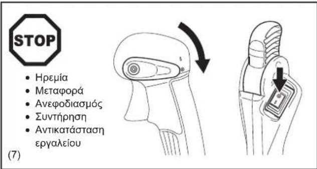
natural_image
Illustration of a soldier in combat gear with a campfire and smoke, no text or symbols presentΠρώτες βοήθειες
natural_image
Simple black square with a white cross symbol in the center (no text or numbers)(12)
2000/14/EK, 2006/42/EK
3-11-8, Sumiyoshi-cho,
Anjo, Aichi, JAPAN
TEXNIKA ΣΤΟΙΧΕΙΑ
text_image
Technical diagram showing a mechanical component with labeled parts and an inset magnified view of a device's internal structure.text_image
(6) (8) (7)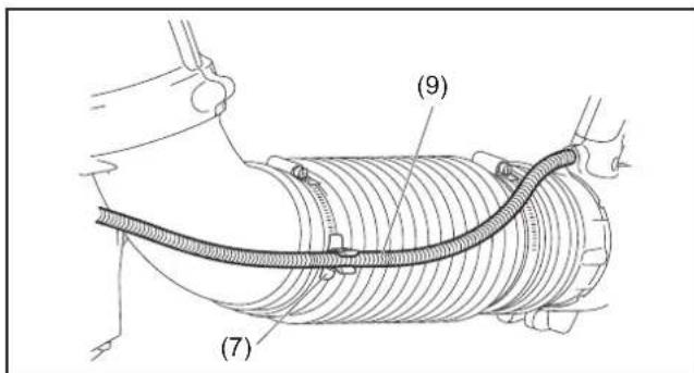
text_image
(7) (9)text_image
(10) (11)natural_image
Line drawing of a mechanical device with an arrow indicating direction (no text or symbols present)
text_image
Diagram showing a hand operating a valve mechanism with labeled parts and directional arrow indicating rotation or movement.ΣΗΜΕΙΩΣΗ:
text_image
Diagram showing car air condition indicators with sun and snow symbols, likely illustrating weather or environmental conditions.ΜΕΘΟΔΟΣ ΛΕΙΤΟΥΡΓΙΑΣ
text_image
(A)(B) (1) (2)text_image
(C)(D) (3) (4)natural_image
Line drawing of a person wearing a backpack and belt, holding a belt buckle (no text or symbols)text_image
Technical diagram showing mechanical assembly with labeled component (1) and magnified detail viewtext_image
Technical diagram showing mechanical assembly with magnified detail and directional arrows indicating motion or forcenatural_image
Line drawing of a person wearing a backpack and holding a long, horn-like device (no text or symbols)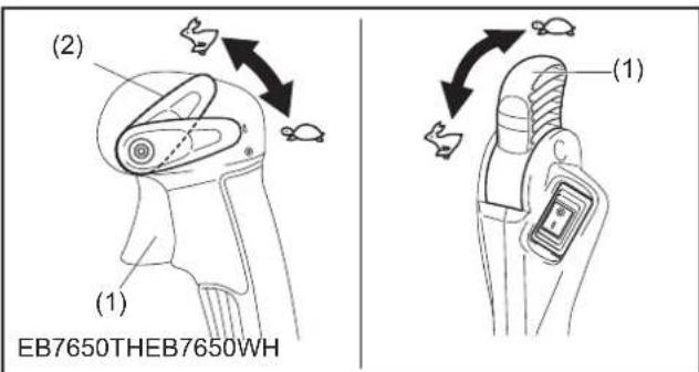
text_image
(2) (1) (1) EB7650THEB7650WH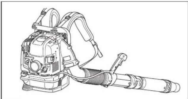
natural_image
Technical line drawing of a mechanical device with hoses and a cylindrical shaft (no text or symbols)
text_image
(1)text_image
(1) (A)(B) (1)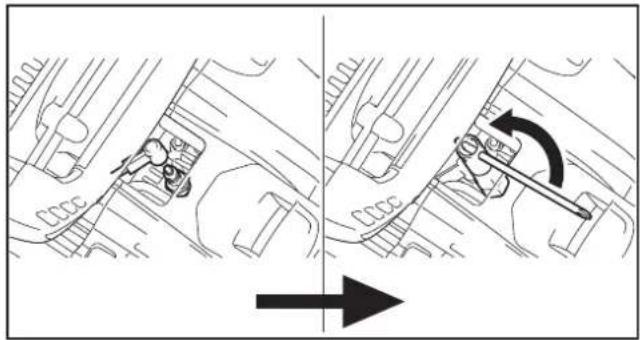
natural_image
Technical diagram showing mechanical assembly with directional arrow (no text or symbols)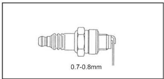
text_image
0.7-0.8mmnatural_image
Technical line drawing of a mechanical component with internal structure and a separate connector (no text or symbols)ΑΠΟΘΗΚΕΥΣΗ
⚠️ ΠΡΟΕΙΔΟΠΟΙΗΣΗ:
natural_image
Two symbolic icons: an open book and a triangular warning sign with an exclamation mark (no text or labels)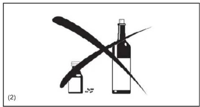
natural_image
Illustration of a wine bottle and its cross-shaped pen, with scattered pills and a quill pen (no text or symbols)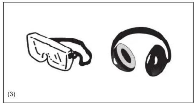
natural_image
Illustration of two types of headphones, one with a curved head and the other with a black-framed ear (no text or symbols)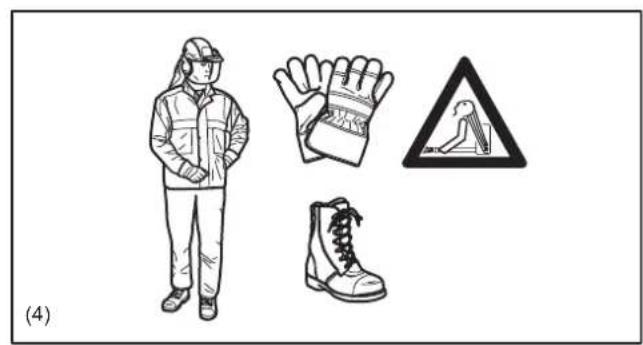
natural_image
Illustration of a person in protective gear, gloves, and boots with hazard symbols (no text or labels)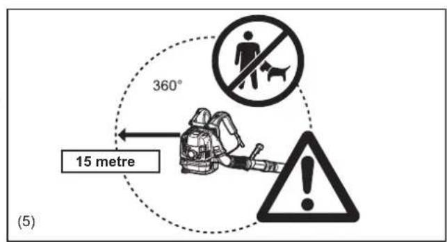
text_image
360° 15 metre (5)natural_image
Line drawing of a mechanical device with hands and a black arrow indicating direction (no text or symbols)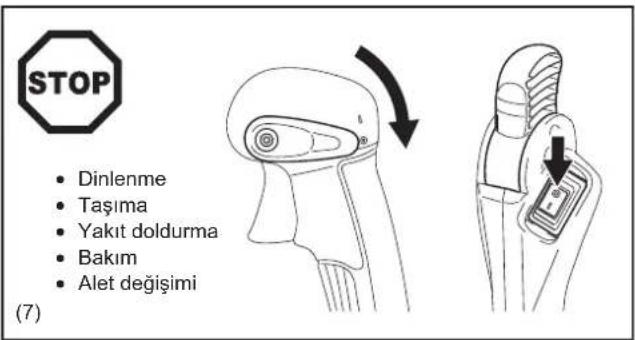
natural_image
Illustration of a person in a hooded shirt with a fire and smoke nearby (no text or symbols)İlk Yardım
natural_image
Simple black square with a white cross symbol in the center (no text or numbers)(12)
2000/14/EC, 2006/42/EC
3-11-8, Sumiyoshi-cho,
Anjo, Aichi, JAPONYA
TEKNİK BİLGİLER
text_image
Technical diagram showing a mechanical component with labeled parts (4) and (5), including a magnified inset of a device detail.text_image
(6) (8) (7)
text_image
(7) (9)text_image
(10) (11)MOTORU BAŞLATMADAN ÖNCE
natural_image
Line drawing of a mechanical device with an arrow indicating a process or operation (no text or symbols present)
text_image
Diagram showing a hand operating a valve mechanism with labeled parts and directional arrow indicating rotation or movement.NOT:
text_image
Technical diagram showing mechanical assembly with labeled parts (1), (2), and (3) indicating different components or states.text_image
Diagram showing car interior components with sun and snow icons, one pair of pointing to a circular component with star symbolsÇALIŞTIRMA YÖNTEMİ
text_image
(A)(B) (1) (2)text_image
(C)(D) (3) (4)natural_image
Line drawing of a person wearing a backpack and belt, holding a belt buckle (no text or symbols)text_image
Technical diagram showing mechanical assembly with labeled component (1) and directional arrows indicating movement or forcetext_image
Technical diagram illustrating mechanical assembly and force application, with labeled parts and directional arrowsnatural_image
Line drawing of a person wearing a backpack and holding a long, handheld device (no text or symbols)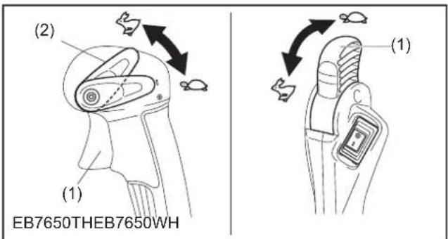
text_image
(2) (1) EB7650THEB7650WH (1)ÜFLEME MAKİNESİNİN NAKLEDİLMESİ VE SAKLANMASI
⚠ DİKKAT:
natural_image
Technical line drawing of a mechanical device with hoses and a cylindrical shaft (no text or symbols)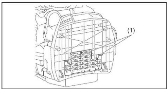
text_image
(1)KONTROL VE BAKIM
⚠️ DİKKAT:
text_image
(1) (A)(B) (1)
natural_image
Mechanical assembly diagram showing two stages of a device with an arrow indicating direction (no text or symbols present)