Skyride 243 Alu - Bike Puky - Free user manual and instructions
Find the device manual for free Skyride 243 Alu Puky in PDF.
| Brand | Puky |
| Model | Skyride 243 Alu |
| Category | Children's bike |
| Wheel size | 24 inches |
| Seat height (min/max) | 65 cm / 81 cm |
| Maximum allowed load | 100 kg |
| Frame | Aluminum |
| Brakes | Rim brakes (V-brake) and coaster brake |
| Drivetrain | Derailleur or hub gears depending on model |
| Lighting | LED with dynamo |
| Tires | Recommended pressure indicated on the sidewall |
| Rim material | Aluminum |
| Maintenance | Oil the chain regularly, clean with non-aggressive products, avoid high-pressure cleaners |
| Safety | Helmet mandatory, obey traffic rules, child at least 8 years old on public roads |
| Wear parts | Tires, inner tubes, rims, brake cables, brake pads, chain, chainrings, grips |
| Warranty | Legal warranty for hidden defects |
| Use | On roads and hard-packed paths, not on rough terrain or jumps |
| Handlebar height adjustment | Quill stem or Ahead (depending on model) |
Frequently Asked Questions - Skyride 243 Alu Puky
User questions about Skyride 243 Alu Puky
0 question about this device. Answer the ones you know or ask your own.
Ask a new question about this device
Download the instructions for your Bike in PDF format for free! Find your manual Skyride 243 Alu - Puky and take your electronic device back in hand. On this page are published all the documents necessary for the use of your device. Skyride 243 Alu by Puky.
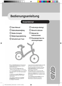
USER MANUAL Skyride 243 Alu Puky
Please read carefully before using the bike for the first time and keep in a safe place for future reference!
text_image
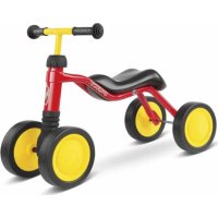
Technical diagram showing mechanical assembly with labeled components (A), B, and a circular gauge indicating 1 unit.Congratulations on the purchase of this PUKY road bike. You have acquired a quality product. This User Manual contains information regarding the safe operation and maintenance of this new bicycle.
Should you have any questions, please contact your dealer or contact us via our website: www.puky.de.
The first journey
The initial contact between your child and the public road traffic system makes high requirements of your child and of your supervision obligations. We recommend ensuring that you do not ask too much of your child. The following safety notes must be taken into account if the child does not have a well-founded sense of balance developed by way of early training with a scooter, balance bike or play bike.
First practice cycling with your child in a suitable safe place, before allowing them to ride independently on public roads.
Avoiding risks
Only when your child is capable of riding safely, may you permit them to use the public roads. In order for your child to conduct themselves correctly on the road, it is important that they are familiar with the key basic principles of the highway code. Do not ask too much of your child. Other road users, especially cars, will unsettle a new, inexperienced road user.
Cycling techniques
Before starting your first journey, explain the operation of the bicycle to your child. The child must be allowed time to familiarise themselves with the various components of the bicycle before starting out. This applies, in particular, to the way the brake works. In a safe place (e.g. on a street with no traffic), practice braking with your child. Braking too hard with the brake on the front wheel may cause the front wheel to block resulting in a fall. Take care when wet or on gravel! If bike paths are available, these should be used. Adults should set a good example.
Legal notes:
Your new children's road bike meets all the requirements of the German Road Traffic Licensing Regulations (StVZO) and may thus be used on the roads. The prerequisite for this is that the child is 8, otherwise they must use the pavement. Using the pavement is permitted until they reach the age of 10.
Using the bike
The overall load permitted for this bike (rider plus bicycle and any luggage) is 20" max. 60 kg; 24" max. 100 kg. The load that may be placed on the luggage rack will depend on the version of the rack (see the embossing on the rack). Models that are supplied without luggage rack may subsequently be fitted with a suitable rack. For road safety reasons, we do not recommend using the rack for carrying loads.
The bicycle may only be used on paved paths and roads without obstacles. The bicycle is not suitable for jumps, tricks or cross-country use.
The bicycle is not suitable for mounting child seats, trailers or tag along bikes. Pay attention to potential hazards when using and maintaining.
Cycle helmet and clothing
Make sure that your child can be seen in good time. To do this, ensure that the child wears bright, attention-grabbing clothing (if possible, including reflective materials). PUKY recommends wearing a well-fitted helmet in accordance with DIN EN 1078, with CE mark (see PUKY accessories).
Unpacking and scope of delivery
Do not use any sharp objects when opening the packaging and removing protective material. By doing so, you may damage the paint or parts of the bike.
Keep all packaging material out of reach of children.
■ Remove all parts from the packaging.
■ Remove the protective material.
Examine the package for completeness and proper condition. If anything is missing, please contact your dealer before you continue to assemble the bike.
Assembly and first use
Prepare the bicycle for use by adjusting it to the height of the child. The saddle is to be set so that at least the toes, but preferably the ball of the foot, reach the ground in order to ensure balance can be achieved when at a standstill. In doing so, the marking showing the minimum insertion depth on the saddle post into the frame tube must be observed. For more information, see below.
When mounting the pedals, observe the right and left threads (labelled on the pedal axis with a R or L in the vicinity of the thread).
After assembly, please conduct a safety check in accordance with the safety checklist!
You will require the following tools for assembly:
■ Allen key 4 mm, 5 mm and 6 mm
■ Open-jawed spanner 15 mm
■ Cross-headed screwdriver
Setting the seating position
Setting the height of the saddle:
Figure 1: The saddle can be pulled out after releasing the saddle clamp with the aid of an Allen key, sized 5 mm. Set the saddle so that at least the toes, preferably the ball of the foot, reach the ground in order to ensure balance can be achieved when at a standstill.
The minimum insertion depth of the saddle post is labelled with a mark. The saddle post may not be extended out of the frame tube beyond this mark. Then retighten the saddle clamp (torque 5-8 Nm).
Please observe the following principles:
Minimum height of the saddle as follows:
20" Crusader / Skyride: 59 cm
24" Crusader: 67 cm
24" Skyride: 65 cm
Maximum height of the saddle:
20" Crusader: 68 cm Skyride: 71 cm
24" Crusader: 82 cm
24" Skyride: 81 cm
Setting the handlebar height for models with shaft stem:
Figure 2: Please, adjust the seating position so that the child is seated upright and a good overview is ensured. The handlebar, hand brake lever and bell must be easy for the child to reach. The minimum insertion depth of the stem is marked on the stem shaft. The stem may not be extended out of the steerer tube (forked) beyond this mark.
The torque for the clamping of the stem in the steerer tube shaft: 15 Nm.
The torque for the clamping of the handlebar in the stem: 10 Nm.
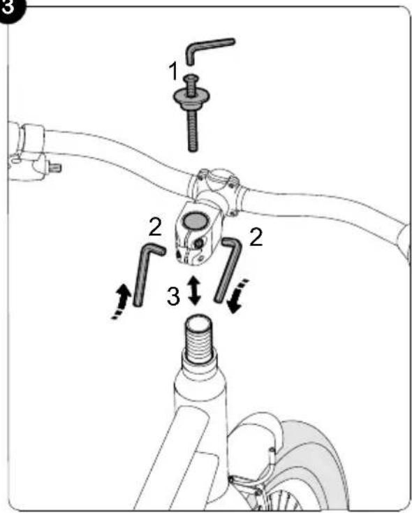
Setting the handlebar height for models with ahead stem:
The handlebar has been set at the factory to the highest position, thus, all spacers are located under the stem. If required, remove the stem and adjust the spacers to lower the handlebar height.
Figure 3: First undo and remove the ahead cap (1). Then undo the two steerer tube clamping screws (2). Now the stem can be removed from the steerer tube (3). Now set the handlebar height according to requirement.
Possible positions are:
All spacers located under the stem (highest handlebar position, set at the factory)
■ Spacers over the stem and under (medium handlebar position)
All spacers above the stem (lowest handlebar position)
No spacers may be removed!
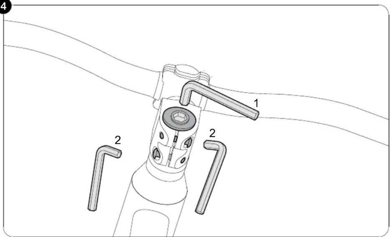
Figure 4: After rearranging the spacers, fit the ahead cap again, align the handlebars to be straight in the direction of travel and set the play of the control bearing correctly. To do this, use the setting screw in the ahead cap (1).
Correct setting: The handlebars must be easy to turn without play in the control bearing.
Now tighten up the steerer tube clamping screws of the stem with the correct torque (2).
The torque for the clamping of the stem on the steerer tube shaft: 5-6 Nm. Make sure that the stem is firmly mounted to the steerer tube and cannot rotate.
Adjusting the brakes:
The bicycle has two calliper brakes. The left brake lever operates the brake on the front wheel, the right brake lever operates the brake on the rear wheel. Depending on the model, the bicycle may also have a back pedal brake for the rear wheel.
Figure 5: Centre the brake arms (1) by turning the adjusting screw. The gap between the brake pad <-> rim should be identical on both right and left and the contact between brake pad/rim should be applied simultaneously on both sides when you brake. You will need a cross-headed screwdriver. By turning the screw in, you move the appropriate brake arm away from the rim, turning the screw out moves the screw towards the rim.
It is important that the brake levers are actuated several times so that the tension of the brake arms is evenly distributed to both sides and the settings take effect.
Figure 6: The handle distance (distance of brake lever to handlebar) can be adjusted individually using an Allen key on the brake handle. Please remember that braking must taken effect before the brake lever reaches the handlebar!
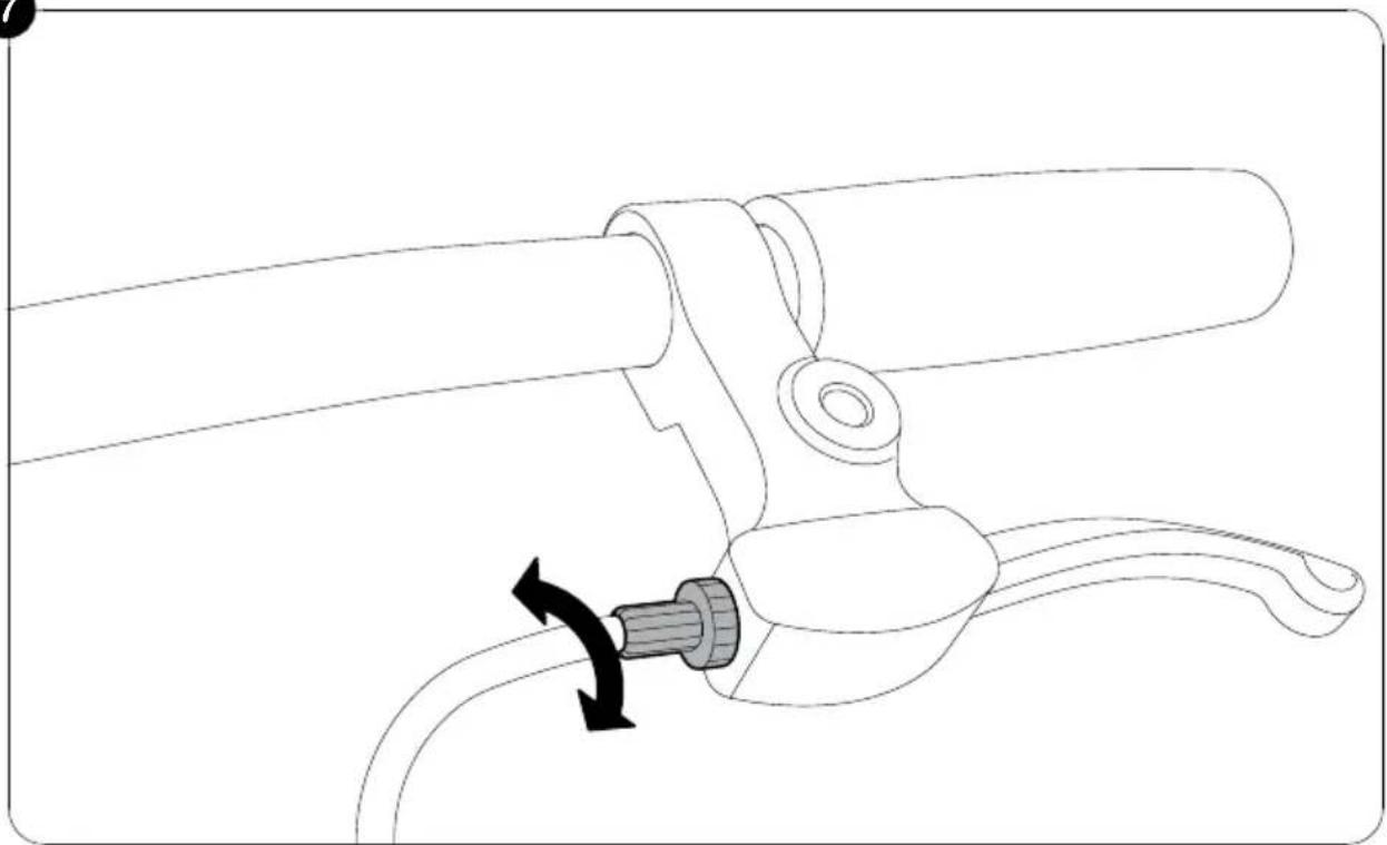
Figure 7: The tension can be set on the brake handle using the knurled screw.
The brake is set correctly if the brake pads are all approximately 1.5 mm from the rims.
Replacing the brake pads
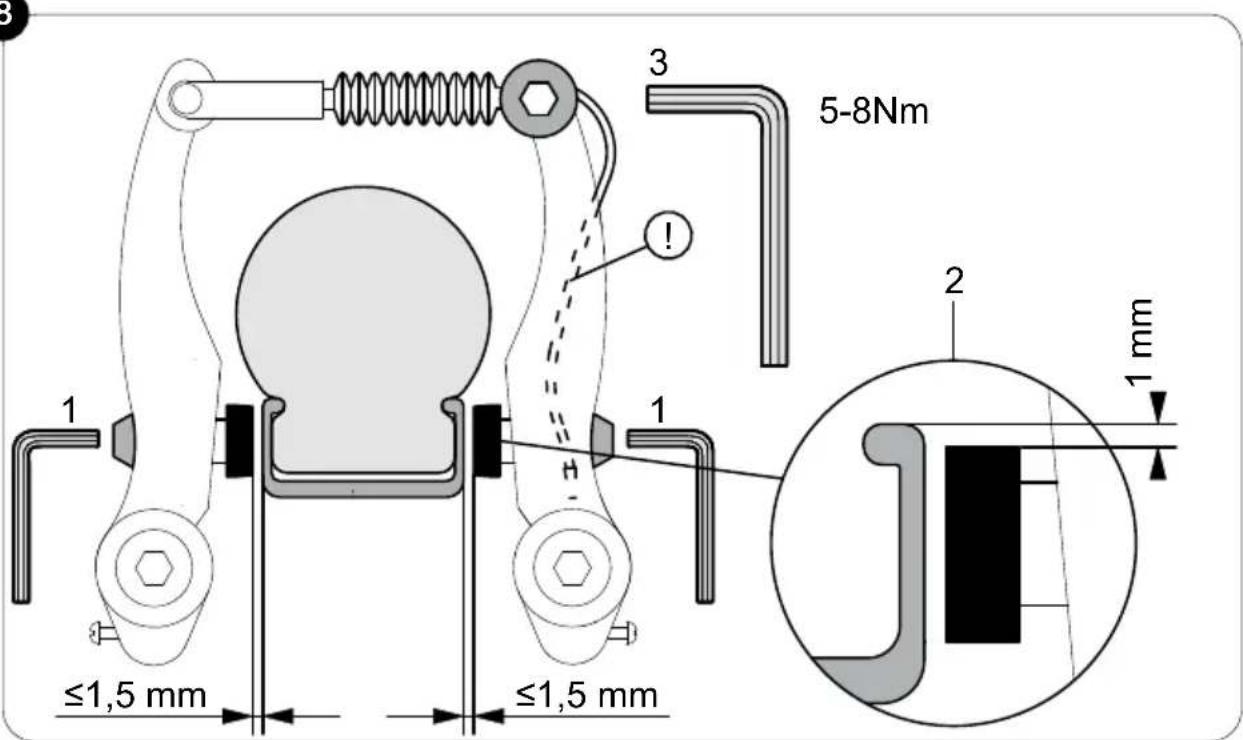
Figure 8: Undo the fastening nut of the brake pad using an Allen key sized 5 mm (1) and replace the brake pads.
This means that the brake pads should rest 1 mm below the top edge of the rim (2). If these settings are not correct, loosen the fastening nut of the brake pad (1) with a 5 mm Allen key and align as described above. To do so, pull the brake lever and re-tighten the fastening nut (5-8 Nm).
The tension is to be set so that the brake pads are all approximately 1.5 mm from the rims. If subsequent adjustment is necessary, undo the tensioning screw (3) and adjust the tension (tighten the tensioning screw back up using 6-8 Nm!) or carry out the step described in Figure 7.
Setting the chain tension (models with gear hub)
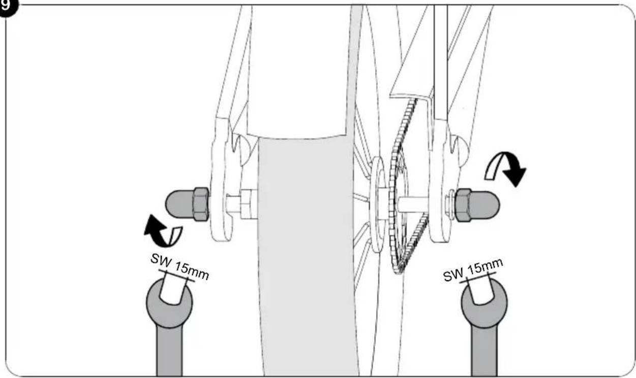
The chain should have a vertical play of approximately 1.5 cm. The setting of the chain tension is carried out as follows:
Figure 9: Undo both wheel nuts of the rear wheel. Adjust the chain tension by sliding the rear wheel at the dropout. Then tighten the wheel nuts back up again (torque 20 Nm). For models with derailleur gears, the chain tension is regulated via the gears.
Attention should be paid to ensure that the correct chain length is selected when replacing the chain.
Setting the gears (model with 3-gear hub)
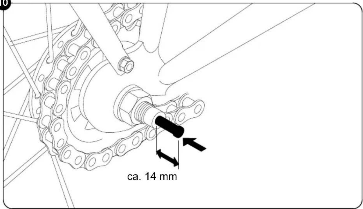
Installation of gear stick
Figure 10: Take the gear stick out of the poly bag and insert it into the right side of the rear axle (in driving direction) until it stops at the black spring.
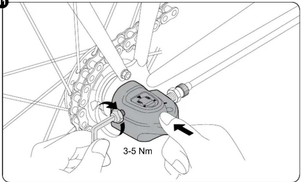
Figure 11: Then you can mount the gearbox onto the rear axle and tighten it with a 5 mm Allen key (3-5 Nm.)
No further settings need to be made to the gearbox.
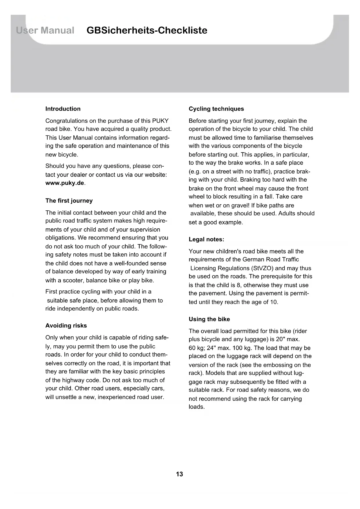
- Setting the limiter for the hardest gear
Rotate the upper setting screw in such a way that, looking from the rear, the guide roller is parallel to the contour line of the smallest gear.
text_image
Technical diagram of a bicycle's wheel assembly with labeled components and directional arrows indicating rotation or movement.(A) Contour line of the smallest gear
(B) Guide roller
(C) Upper setting screw
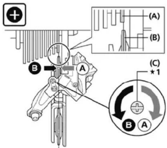
- Setting the limiter for the easiest gear
Rotate the lower setting screw in such a way that the guide roller is in position along the largest gear.
text_image
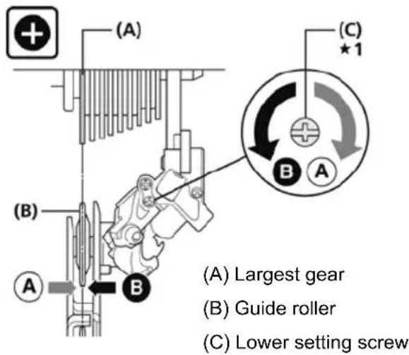
(A) (B) (A) Largest gear (B) Guide roller (C) Lower setting screw- Setting the tension
Carry out fine adjustments of the gear positions by turning the tension setting screw. Rotating anti-clockwise eases switching to the next largest gear. Rotating clockwise eases switching to the next smallest gear.
text_image
(A) (A) Setting screw for tensionYou should only carry out setting of the chain gears if you are capable of doing so. If in doubt, have this carried out by a specialist.
Maintenance and care
For reasons of safety, the first check of the bicycle should be carried out after the first few hours of cycling. All maintenance work requires specialist knowledge. Please consult your specialist dealer if you are not sure whether you are able to carry it out yourself.
Cleanliness and corrosion protection
All painted and metallic surfaces can be cleaned and protected using ordinary car care products. Only use environmentally friendly products and never use any aggressive detergents.
Regularly oil the chain (chain or universal oil) and clean when necessary.
The flanks of the rims (braking surfaces) must be grease-free!
The vehicle is to be protected from winter salt and long periods of storage in damp spaces (e.g. garage) are to be avoided. If you do store the bicycle in a damp environment, protect the surfaces of unpainted metal parts (screws, nuts etc.) with a suitable surface seal (e.g. spray wax).
Hub and ball bearing should be checked from time to time by a specialist, adjusted and lubricated as required. Do not use a pressure washer/steam cleaner to clean.
Lights
The lights are based on LED technology which is characterised by its low consumption and long lifetime.
To check the lighting system, raise the front wheel and spin it.
Brakes
Please pay attention to the reduced effect of the brakes on the front wheel when it is wet. Sudden, forceful braking with the rim brake should be avoided (V-brakes in particular have very high braking performance) since the behaviour of the vehicle may suddenly change as a result, which may end in a fall.
On long slopes, long periods of braking with the back pedal back are to be avoided (this results in excess heat to the back pedal brake nave).
If the handbrake lever can be pulled more than half-way to the handlebar, the brake must be adjusted. The braking surfaces must be clean, grease-free and the brake pads must be parallel to one another. This means that the brake pads should rest 1 mm below the top edge of the rim and be mounted at a slight angle to rim.
Worn pads must be replaced immediately!
When replacing, make sure you use original pads or ensure that they match the material of the rim at least (e.g. see the label: "Alloy / Alu" for aluminium rims).
Caution in the event of rim wear
Regularly check the state of the rims and pay special attention to the wear groove which surrounds the rim. Consult your specialist workshop in good time (when the groove is almost worn away). Breakage and accident risks!
Check the chain tension and adjust as necessary (if required, by loosening the rear wheel, aligning and tightening again).
Pay attention to the correct air pressure (the prescribed pressure is indicated on the sides of the tyres). Do not repair damaged or deformed parts. Damaged or deformed parts must be replaced. Original replacement parts can be obtained from your PUKY dealer.
Spare parts: Tyres (including tubes), rims, brake cable, brake pads, chain, chain rings, handle covers.
The bicycle is, like all mechanical components, exposed to wear and high loads. Different materials and components may react in different ways to wear or use due to loads. If the intended lifetime of a component is exceeded, it may suddenly fail and this may cause injury to the rider. Any type of crack, groove or change in colour in highly-demanding areas will indicate the expiry of the lifetime of a component and the component should then be replaced.
Practical tip:
Components that are subject to relatively high wear are, in particular: Tyres (including inner tubes), rims in conjunction with rim brakes, brake pads, brake cables, shift cables, chain, chain rings, bearing, handle covers, bulbs of the lighting system.
Subsequent additions or modifications to the bicycle (especially the braking systems) will change the behaviour of the vehicle and may pose a risk. Before replacing components that may affect road-worthiness (in accordance with German StVZO), make sure that the road-worthiness is not affected by the replacement.
Statutory warranty
Statutory warranty covers defects. Damage resulting from improper use, use of force, lack of maintenance, or normal wear and tear, is excluded from such a statutory defect warranty. In accordance with the German StVZO, the following important functions are to be checked prior to each journey!
Saddle
Saddle cannot be rotated (12 Nm)*
Saddle post cannot be rotated (5-8 Nm)* □
Minimum insertion depth marking observed □
Balls of feet reach the ground ☐
Handlebars/stem (models with shaft stem)
Handlebar shaft tube secured and cannot be rotated (15 Nm)*
Minimum insertion depth marking observed □
Handlebars cannot be rotated in stem (10 Nm)* □
Handles cannot be rotated, upright seating position ☐
Handlebars/stem (models with ahead stem)
Stem cannot be rotated on steerer tube (5-6 Nm)*
Handlebars cannot be rotated in stem (5-6 Nm)* □
Handles cannot be rotated, upright seating position ☐
Handbrakes
Brake lever cannot be rotated (5 Nm) ^* , easily accessible
Functions perfectly □
Brake pad clean, grease-free, positioned correctly ☐
Back pedal brake
Function checked
Chain
Chain tension is OK ( play approximately 1.5 cm)
Sufficient lubrication ☐ Chain guard is complete ☐
Tyres
Sufficient tread/air pressure (air pressure to be maintained is on the tyre)
Wheels
Axle nuts firmly tightened (VR 15 Nm, HR 20 Nm)*
Aligned □
Spokes evenly tightened □
Pedals
Securely and correctly mounted (check L/R)
Rotate easily □
Bell
Clear ring, easy to reach
Headlamps
Securely mounted and correctly set/correctly functioning
Dynamo
Assembly: Direction of operation, easy to operate, play-free/moves easily
Good ground contact, connection clean and firm
Rear light
Securely mounted and correctly set/correctly functioning
(*Torques of screws in Newton metres)
Inleiding
text_image
Technical diagram of a mechanical assembly with labeled components and directional arrows, including section (A) and section (C) with annotations.text_image
Technical diagram of a bicycle's wheel assembly with labeled components and directional arrows indicating motion or positioning.text_image
Technical diagram of a mechanical assembly with labeled components and directional arrows, including section views A and B.(A) Det mindste tandhjuls konturlinje
(B) Styrerulle
(C) ∅verste indstillingsskrue
text_image
Technical diagram showing mechanical assembly with labeled components (A, B) and a circular component marked with '★1' indicating a specific section.text_image
Technical diagram showing mechanical assembly with labeled components (A), B, and a crosshair view highlighting component (C) with dimension 1.text_image
Technical diagram showing mechanical assembly with labeled components (A), B, and C, including a magnified view of internal structure.text_image
Technical diagram of a bicycle wheel assembly with labeled components and directional arrows indicating rotation or adjustment.text_image
(A) (A) aju catext_image
Technical diagram showing mechanical assembly with labeled components (A), B, and C, including a magnified view of internal structure.natural_image
Diagram showing a bicycle handle assembly with a magnified view of the handle (no text or symbols present)Montage
Assembly
Montage
Assemblée
Montering
Assemblaggio
Monta'z
Montá'z
Montaje
Монтаж
3
text_image
Diagram showing a bicycle steering wheel assembly with numbered parts and directional arrows indicating motion or movement.4
text_image
Technical diagram of a mechanical device with labeled parts 1 and 2, showing internal components and connection lines.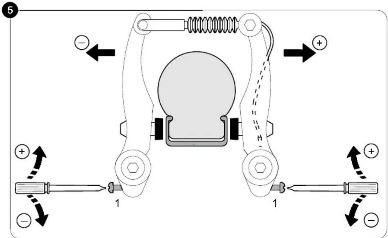
text_image
5 + + - 1 1 1 +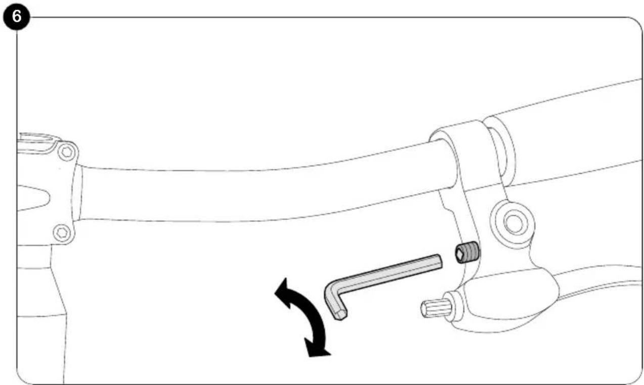
natural_image
Technical line drawing of a mechanical clamp or lever assembly with a directional arrow indicating motion (no text or symbols present)Montage
Assembly
Montage
Assemblée
Montering
Assemblaggio
Monta'z
Montá'z
Montaje
Монтаж
7
natural_image
Line drawing of a mechanical component with a knob and cable, showing a directional arrow indicating rotation (no text or symbols)8
text_image
5-8Nm 1 ≤1,5 mm ≤1,5 mm 2 1 mm9
text_image
SW 15mm SW 15mm10
text_image
ca. 14 mmMontage
Assembly
Montage
Assemblée
Montering
Assemblaggio
Monta'z
Montáž
Montaje
Монтаж
11
text_image
3-5 NmPlease complete the identification plate on the cycle passport page. The PUKY identification plate is fitted to the vehicles as shown in the drawings below and must be noted down for ordering replacement parts from your dealer.
natural_image
Technical line drawing of a car wheel assembly with suspension components (no text or symbols)Typenschild/Typens child/Identification plate/Typeplaatje/Plaque signalétique/Typeskilt/Targhetta/Oznakowanie produktu/Identifikační štítek/Placa de características/Фирменная табличка
Name/Surname/Naam/Nom/Efternavn/Cognome/Nazwisko/Jméno/Apellido(s)/Фамилия
Vorname/First name/Voornaam/Prénom/Fornavn/Nome/Imię/Příjmení/Nombre/Имя
Straße/Street/Straat/Rue/Gade/Via/Ulica/Město/Vía/Yлицa