
FWXV15ABTV3 - Heat pump DAIKIN - Free user manual and instructions
Find the device manual for free FWXV15ABTV3 DAIKIN in PDF.
| Product Type | Heat pump / Floor fan coil unit |
| Brand | Daikin |
| Model | FWXV15ABTV3 |
| Total cooling capacity | 2.64 kW |
| Sensible cooling capacity | 1.91 kW |
| Heating capacity | 2.86 kW |
| Maximum airflow | 438 m³/h |
| Sound pressure level (max) | 48 dB(A) |
| Power supply | 230 V / 1 phase / 50 Hz |
| Power consumption (max) | 25 W |
| Current draw (max) | 0.18 A |
| Maximum operating pressure | 10 bar |
| Water inlet temperature max/min | 80°C / 4°C |
| Hydraulic connections | 3/4" |
| Weight | 23 kg |
| Water volume in the coil | 1.13 L |
| Maintenance | Regular cleaning of the air intake filter |
| Safety | Safety switch preventing operation without panel |
| Main spare parts | Filter, fan, hydraulic valve |
Frequently Asked Questions - FWXV15ABTV3 DAIKIN
User questions about FWXV15ABTV3 DAIKIN
0 question about this device. Answer the ones you know or ask your own.
Ask a new question about this device
Download the instructions for your Heat pump in PDF format for free! Find your manual FWXV15ABTV3 - DAIKIN and take your electronic device back in hand. On this page are published all the documents necessary for the use of your device. FWXV15ABTV3 by DAIKIN.
USER MANUAL FWXV15ABTV3 DAIKIN
FWXV10ABTV3(R)
FWXV15ABTV3(R)
FWXV20ABTV3(R)
FWXV10AATV3(R)
FWXV15AATV3(R)
FWXV20AATV3(R)
FWXM10AATV3(R)
FWXM15AATV3(R)
FWXM20AATV3(R)
Installation manual Heat pump convector
EN
We want to thank you for choosing one of our products.
We are confident that you will be happy with your selection because it represents the state of the art in the technology of home climate control.
By following the suggestions contained in this manual, the product you have purchased will operate without problems giving you optimum room temperatures with minimum energy costs.
DAIKIN EUROPE N.V.
Conformity
This unit complies with European directives:
Low voltage directive 2014/35/UE Electro-magnetic compatibility 2014/30/UE;
Symbols
The following symbols provide the necessary information for correct, safe use of the machine in a rapid, unmistakable
way
Editorial pictograms

User
- Refers to pages containing instructions or information for the user.

- Refers to pages containing instructions or information for the installer TECHNICAL CUSTOMER SERVICE.

Installer
- Refers to pages containing instructions or information for the installer
Safety pictograms

Signals that the operation described could cause physical injury if not performed according to the safety rules.

- Signals that the operation described could cause bums if not performed according to the safety rules.

Signals that the operation described could cause electrocution if not performed according to the safety rules.
- Refers to actions that absolutely must not be performed.
General
1.1 General warnings 4
1.2 Fundamental safety rules 4
1.3 Product range 5
1.4 Overall dimensions 6
Installation
2.1 Positioning the unit 7
2.2 Installation modes 7
2.3 Minimum installation space 7
2.4 Access to the internal components 8
2.5 Removing the side panels.. 9
2.6 Vertical installation 9
2.7 Horizontal or ceiling installation 10
2.8 Hydraulic connections 10
2.9 Condensation discharge 11
2.10 Filling the system 12
2.11 Evacuating air while filling the system. 12
2.12 Electrical connections 13
2.13 Maintenance 13
2.14 Cleaning the outside. 13
2.15 Cleaning air suction filter 14
2.16 Energy saving tips 15
Troubleshooting
3.1 Troubleshooting 16
3.2 Table of anomalies and remedies 16
3.3 Technical Data 18
GENERAL
1.1 General warnings
After unpacking, make sure that all the components are present. If not, contact your installer of your DAIKIN affiliate office.
DAIKIN appliances must be installed by an authorised installer who, on completion of the work, will release a declaration of conformity to the client in respect of the laws in force and the indications given by DAIKIN in the instructions leaflet supplied together with the appliance.
A Those appliances have been designed both for conditioning and/or heating environments and must be destined for this use only and compatibly with their performance characteristics.
DAIKIN EUROPE N.V. accepts no responsibility, either contractual or extra-contractual, for any damage caused to persons, animals of property as a result of incorrect installation, adjustment or maintenance or improper use.
In case of water leaks, turn the master switch of the system to "OFF" and close the water taps.
As soon as possible, call the DAIKIN technical service department or else professionally qualified personnel and do not intervene personally on the appliance.
The imbedded FWXM-series do not have a grill or covering plate. Provide safety guards and air inlet/outlet grills to prevent accidental contact with the device.
If the appliance is not used for a long period of time, the following operations should be performed:
- Turn the master switch of the system to "OFF"
- Close the water taps
- If there is the risk of freezing, make sure that anti-freeze has been added to the system otherwise empty the system.
1.2 Fundamental safety rules
Remember that some fundamental safety rules should be followed when using a product that uses electricity and water, such as:
The unit can be used by children over the age of 8, and by people with reduced physical, sensory or mental capabilities, or with no experience or necessary knowledge, as long as they are monitored or after they have received instructions on the safe use of the unit and have understood the dangers involved.
Children must not play with the appliance.
The cleaning and maintenance that must be performed by the user should not be carried out by children without supervision.
If the room temperature is too low or too high it is damaging for the health and is also a useless waste of energy.
Avoid prolonged contact with the direct air flow.
Do not leave the room closed for long periods. Periodically open the windows to ensure a correct change of air.
This instruction leaflet is an integral part of the applianco and consequently must be kept carefully and must ALWAYS accompany the appliance, even when it is passed to a new owner or user or transferred onto another system. If it is lost or damaged, please contact the local DAIKIN technical service centre.
All repair or maintenance interventions must be performed by the technical service department or by professionally qualified personnel as foreseen in this booklet. Do not modify or intervene on the appliance as this could create dangerous situations and the manufacturer will not be responsible for any damage caused.
Danger from bums - take care when touching
It is forbidden to touch the appliance with wet hands or body when barefoot.
It is forbidden to carry out any cleaning before having disconnected the appliance from the electricity mains supply by turning the system master switch to "OFF".
It is forbidden to modify the safety or adjustment devices or adjust without authorisation and indications of the manufacturer.
It is forbidden to pull, cut or knot the electrical cables coming out of the appliance, even if it is disconnected from the mains supply.
It is forbidden to poke objects or anything else through the inlet or outlet grills.
It is forbidden to climb onto the appliance or rest any object on it.
It is forbidden to open the doors which access the internal parts of the appliance without first turning the system master switch to "OFF".
The external parts of the appliance can reach temperatures of more than 70^
It is forbidden to dispose of or leave in the reach of children the packaging materials which could become a source of danger.
1.3 Product range
There are 2 types of DAIKIN heat pump convectors, FWXV and FWXM, each of which is offered in 3 sizes with different performances and dimensions.
FWXV-series
heat pump convector with metal cabinet.
FWXM-series
Embedded heat pump convector without panels.
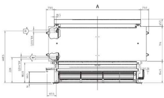
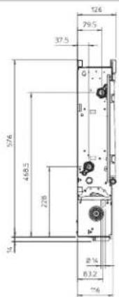
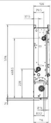
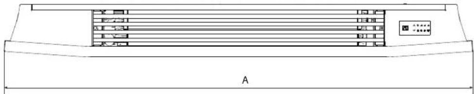
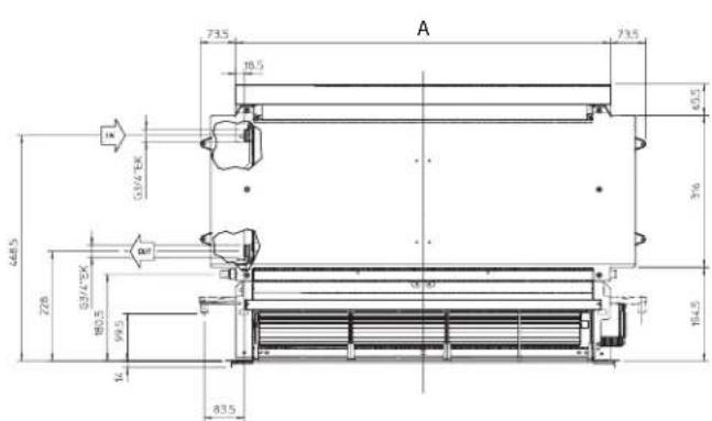
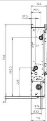
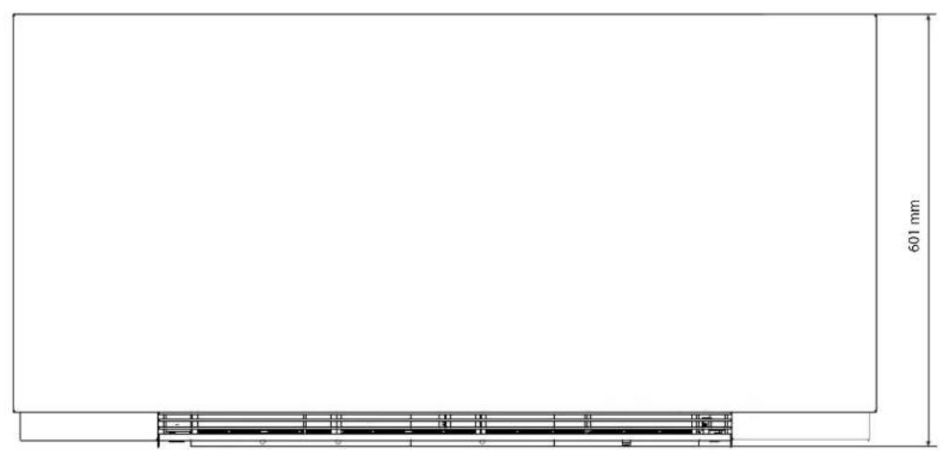
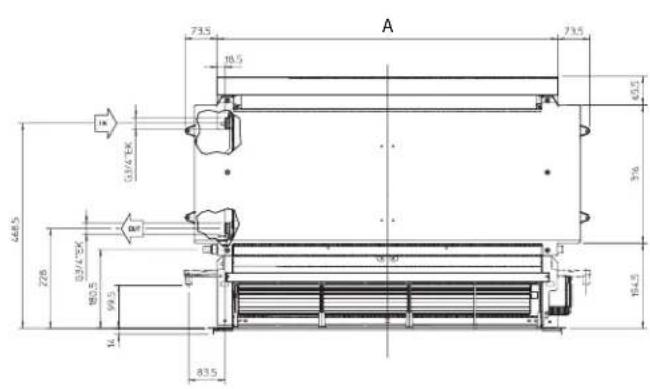
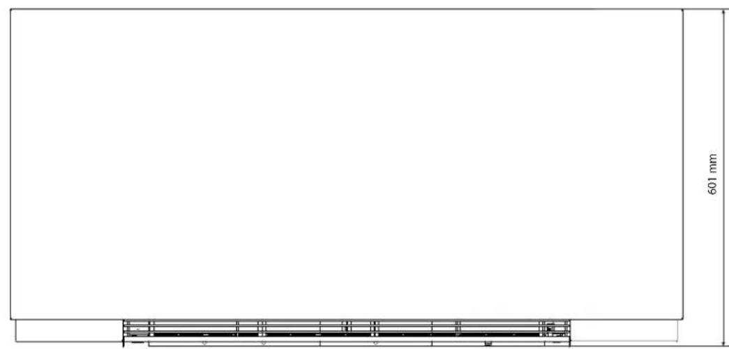
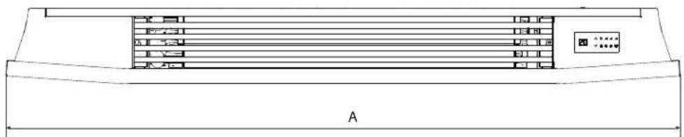
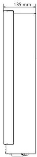
1.4 Overall dimensions
| U.M. | FWXV10AATV3(R) | FWXV15AATV3(R) | FWXV20AATV3(R) | |
| FWXV10ABTV3(R) | FWXV15ABTV3(R) | FWXV20ABTV3(R) | ||
| Dimensions | ||||
| A mm 999 1199 1399 | ||||

FWXV


| U.M. | FWXM10AATV3(R) FWXM15AATV3(R) FWXM20AATV3(R) | |||
| Dimensions | ||||
| A mm 578 778 978 | ||||

FWXM

INSTALLATION
2.1 Positioning the unit
Avoid installing the unit:
- in positions subject to exposure to direct sunlight;
- in proximity to sources of heat;
- in damp areas or places with probable contact with water;
in places with oil fumes - in places subject to high frequency radio waves.
A Make sure that:
the wall on which the unit is to be installed is strong enough to support the weight;
- the part of the wall interested does not have pipes or electric wires passing through;
the interested wall is perfectly flat; - there is an area free of obstacles which could interfere with the inlet and outlet air flow;
the installation wall is preferably an outside perimeter wall to allow the discharge of the condensation outside; - in case of coiling installation (FWXM-series) the airflow is not directed towards persons.
2.2 Installation modes
The following descriptions of the various mounting phases and the relative designs refer to a version of the machine with fixtures on the left.
The operations for the mounting of machines with fixtures on the right (R) are exactly the same.
Only the images are to be considered as a mirror image. To ensure that the installation is performed correctly and
that the appliance will perform perfectly carefully follow the instructions indicated in this manual. Failure to respect the rules indicated not only can cause malfunctions of the appliance but will also invalidate the warranty and hence DAIKIN EUROPE N.V. shall not respond for any damage to persons, animals or property.
2.3 Minimum installation space
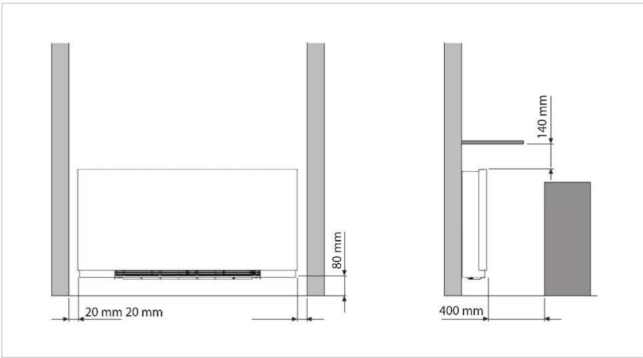
Figure indicates the minimum mounting distances between the wall-mounted cooler-convector and furniture present in the room.
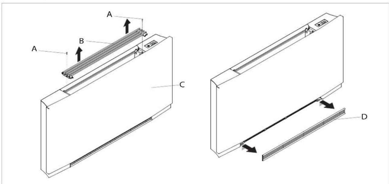
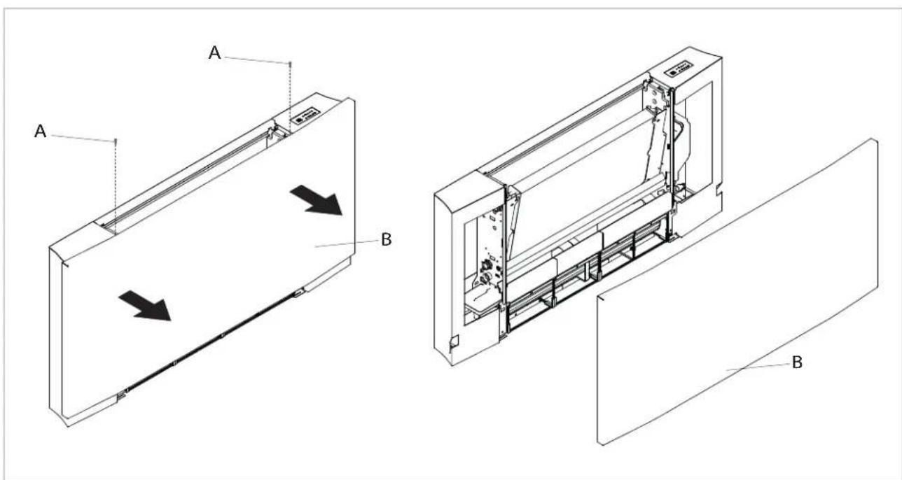
2.4 Access to the internal components
To access the inside of the machine, follow the procedures below.
Remove the upper grill:
- loosen the fixing screws of the upper grill
- remove the grill
Remove the front grill:
- extract the grill until it is completely out of the seat
- tilt the grill
- slide outwards
| A | Fixing screws |
| B | Upper grill |
| C | Front panel |
| D | Front grill |
Remove the frontal panel:
loosen the fixing screws
- remove the panel
A Fixing screws Front panel
B
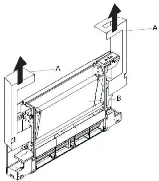
2.5 Removing the side panels
To remove the side:
- remove the sides upwards
A Side
B Machine body
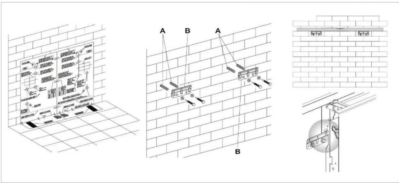
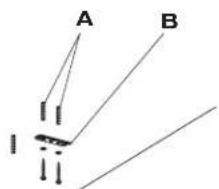
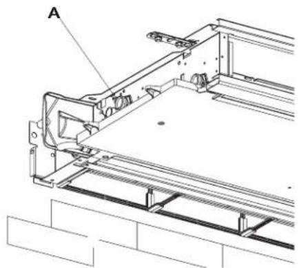
2.6 Vertical installation
Using the paper template, trace the position of the two fixing brackets on the wall. Use a suitable drill to make the holes with and insert the wall plugs (2 for each bracket); fix the two brackets. Do not over-lighten the screws so that the brackets can be adjusted with a spirit level.
Install the unit at level (with a possible 1 to 2% inclination towards the drainage pipe to facilitate the flow of water).
Fully tighten the four screws to block the two brackets.
Check the stability by manually moving the brackets to the right and to the left, up and down.
Mount the unit, checking that it fits correctly onto the brackets and checking that it is stable.
Note: to facilitate the connection of the pipes to the fancoll connections, install a built-in box at the oulet of the pipes themselves.
The correct position of the box is indicated on the installation template.
A Wall plugs Brackets
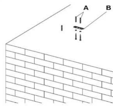
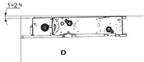
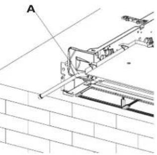
2.7 Horizontal or ceiling installation
Using the paper template, trace on the ceiling the position of the two fixing brackets and the two rear screws. Using a suitable drill, make the holes and insert the wall plugs (2 for each bracket); fix the two brackets. Do not over-tighten the screws. Position the machine on the two brackets, keeping it in position and then fix the two screws into the rear toggle bolts, one on each side.
Install the unit at level (with a possible 1 to 2% inclination towards the drainage pipe to facilitate the flow of water).
For installation of the FWXV-senes, horizontal condensation collection basin accessory kits are available EKM(10/15/20)COH.
Carefully check the inclination of the exhaust pipe. Any counter slope of the discharge line can cause water leakage
A Wall plugs
B Brackets
C Scrows
D Drainage pipe
2.8 Hydraulic connections
FWXV/FWXM U.M. 10AATV3(R) 15AATV3(R) 20AATV3(R)
FWXV U.M. 10ABTV3(R) 15ABTV3(R) 20ABTV3(R)
Pipeline diameter mm 14 16 18
NB: the nominal diameter, unless otherwise indicated, always refers to the internal diameter.
To avoid the formation of surface condensation, it is always recommended to install electric valve kits, except in the case where an electrical control (eg electrothermal head) is provided upstream of the appliance. The choice and sizing of the hydraulic lines must be made by an expert who must operate according to the rules of good technique and the laws in force, taking into account that undersized pipes cause a malfunction.
To make the connections:
position the hydraulic lines
- tighten the connections using the "spanner and counter spanner" method
- check for any leaks of liquid
coat the connections with insulating material.
The hydraulic lines and joints must be thermally insulated.
Avoid partially insulating the pipes.
Do not over-tighten to avoid damaging the insulation.
Use hemp and green paste to seal the threaded connections; the use of Teflon is advised when there is anti-freeze in the hydraulic circuit.
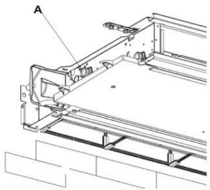
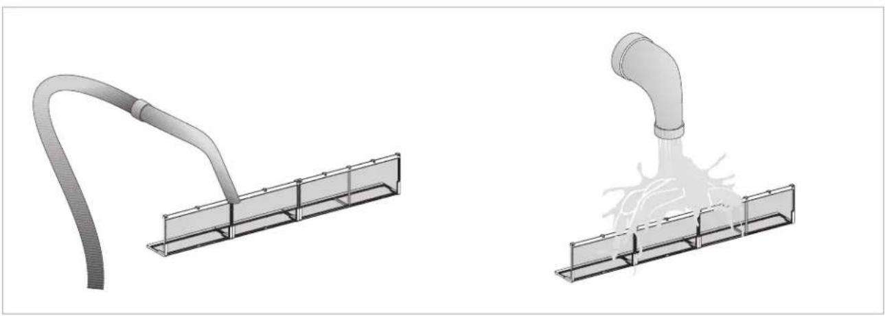
2.9 Condensation discharge
The condensation discharge network must be suitably sized and the pipeline positioned so that it keeps a constant inclination, never less than 1% . In the vertical installation, the discharge pipe is connected directly to the discharge tray, positioned at the bottom of the side shoulder underneath the hydraulic fixtures. In a horizontal installation the discharge tube is connected to the one already present on the machine.
- If possible, make the condensation liquid flow directly in a gutter or a "rainwater" discharge.
-
When discharging directly into the main drains, it is advisable to make a siphon to prevent bad smells returning up the pipe towards the room. The curve of the siphon must be lower than the condensation collection bowl.
If the condensation needs to be discharged into a container, it must be open to the atmosphere and the tube must not be immersed in water to avoid problems of adhesiveness and counter-pressure that would interfere with the normal outflow. -
If there is a height difference that could interfere with the outflow of the condensation, a pump must be mounted:
- in a vertical installation mount the pump under the lateral drainage tray;
- in a horizontal installation the pump position must be decided according to the specific requirements. Such pumps are commonly found in commerce.
However, on completion of the installation it is advisable to check the correct outflow of the condensation liquid by slowly pouring about 12 of water into the collection tray in about 5-10 minutes.
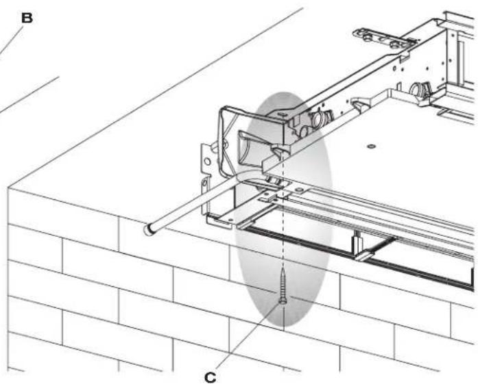
Mounting the condensation discharge pipe in the vertical version
Connect a drainage pipe to the drainage connection of the condensate tray and block it properly. Check that the
drip-collector extension is present and correctly installed.
| A | Discharge fitting |
| B | Tube for the outflow of the liquid - Ø14 mm |

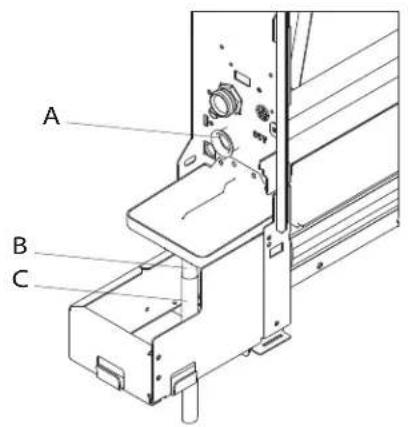
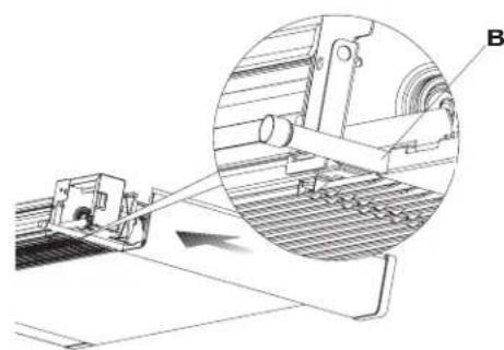
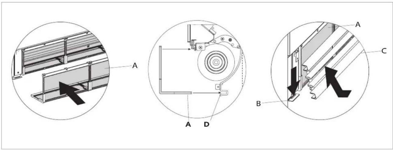
Mounting the condensation discharge pipe in the horizontal version
To mount the horizontal bowl on the FWXM-series refer to the instructions in kits EKM(10/15/20)COH.
- check that the "L" pipe and the flexible rubber hose are correctly connected to the bowl.
- slide in the side of the machine keeping the pipe in position up against the front grill.
- fully close the side checking that the pipe remains blocked in the special grove on the side.
N.B. for the horizontal installation carefully note the following precautions:
make sure that the machine is installed perfectly level or with a slight inclination towards the condensation discharge;
insulate carefully the inflow and outflow pipes up to themachine union to prevent any drops of condensation outside the same collection bowl;
insulate the bowl condensation discharge pipe along all of its length.
A Connection pipes - 014 mm Discharge
B
2.10 Filling the system
When starting up the system, make sure that the hydraulic unit lockshield is open. If there is no electric power and the
thermo-valve has already been powered use the special cap to press the valve stopper to open it.
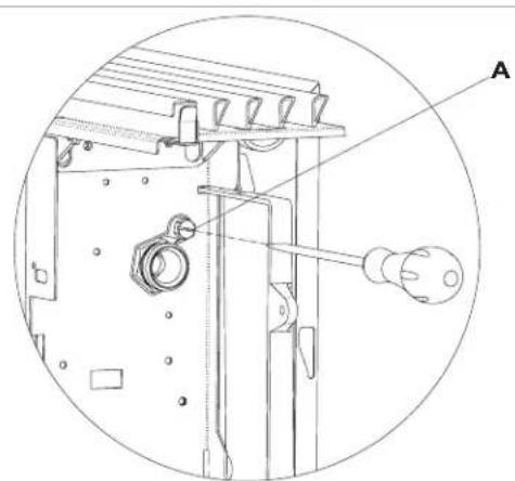
2.11 Evacuating air while filling the system
- Open all the shut off valves (manual or automatic);
-
Start the filling by slowly opening the system water filling tap;
For the unit installed in a vertical position, take a screwdriver and open the highest breather of the heat exchanger; for appliances installed in a horizontal position, open the highest positioned breather. -
When water starts coming out of the breather valves of the appliance, close them and continue filling until reaching the nominal value for the system.
Check the hydraulic seal of the gaskets.
It is advisable to repeat these operations after the appliance has been running for a few hours and periodically check the pressure of the system.
A Breather
2.12 Electrical connections
Make electrical connections according to the requirements set out in sections General Warnings and Fundamental Safety Rules by reference to the patterns present in the installation and accessories manuals.
Before doing any work, make sure the power is switched off.
The unit must be connected to the mains through a multipolar switch with minimum contact opening of at least 3mm or with a device that allows the complete disconnection from the device under the overvoltage conditions category III.
2.13 Maintenance
Routine maintenance is indispensable to keep the heat pump convector in perfect working condition, safe and reliable over the years. This can be done every six months
for some interventions and annually for others, by the Technical Service Assistance, technically authorised and prepared, using always original spare parts.
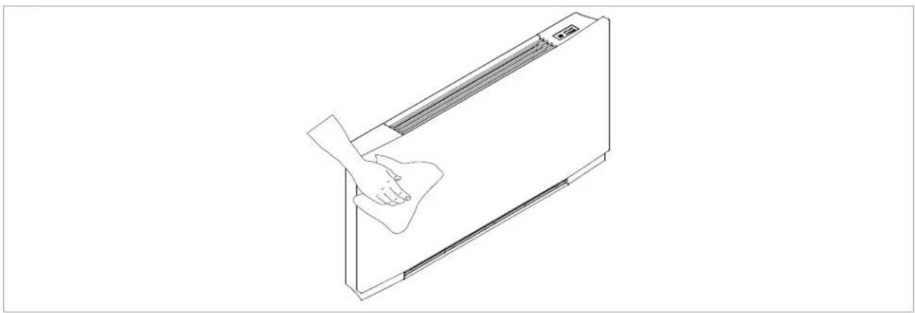
2.14 Cleaning the outside
Before every cleaning and maintenance intervention, disconnect the appliance from the mains by switching off the master switch.
Do not use abrasive sponges or abrasive or corrosive detergents to avoid damaging the painted surfaces.
Wait until the parts have cooled down to avoid the risk of burns.
When necessary, clean the outer surfaces of the heat pump convector with a soft damp cloth.
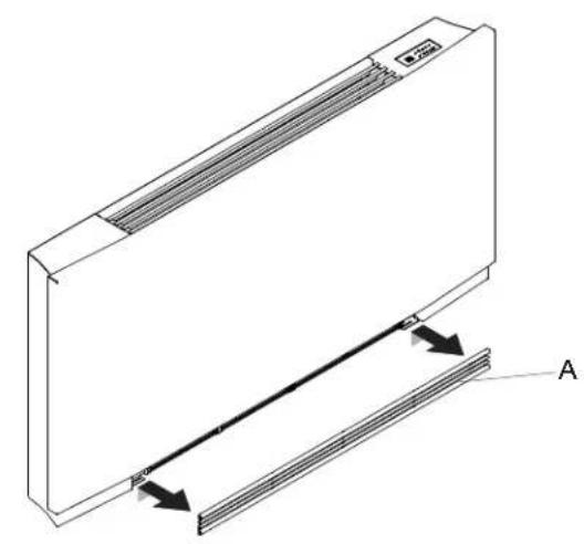
2.15 Cleaning air suction filter
After a period of continuous operation and in consideration of the concentration of impurities in the air, or when
he intends to restart the unit after a period of inactivity, proceed as described.
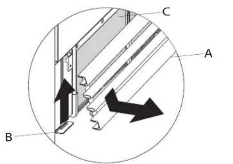
Extraction of filter cells
To remove the grill:
- lift the grill until it is completely released from the seat
-
tilt the grill and slide it outwards
-
then remove the filter by pulling it outwards
| A | Front grill |
| B | Grill hook |
| C | Filter |
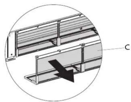
Cleaning filtering seats
- suck up the dust with a vacuum cleaner
- wash the filter with running water without using detergents or solvents, and leave to dry.
It is forbidden to use the unit without the net filters.
The appliance is fitted with a safety switch that prevents the operation of the fan with the mobile panel missing or out of position.
After finishing the cleaning of the filter, check that the panel is mounted correctly.
Ending Cleaning Operations
For the versions with a grill with flaps, insert the two lugs into the special slots, turn it and hook it up with a slight lap on the upper part.
A Filter
B Grill hook
C Front grill
D The filter housing
2.16 Energy saving tips
- Always keep the filters clean;
-
when far possible, keep the doors and windows closed in the room being conditioned;
-
limit where possible the effect of direct sun rays in the rooms being conditioned (use curtains, shutters etc.)
TROUBLESHOOTING
3.1 Troubleshooting
In case of water leaks or anomalous functioning immediately cut off the power supply and close the water taps.
A Should one of the following anomalies occur, contact an authorised service centre or an authorised qualified person, but do not intervene personally.
- The ventilation does not activate even if there is hot or cold water in the hydraulic circuit.
- The appliance leaks water during the heating function.
The appliance leaks water only during the cooling function.
The appliance makes an excessive noise. - There are formations of dew on the front panel.
3.2 Table of anomalies and remedies
The interventions must be carried out by a qualified installer or by a specialised service centre.
| Effect Cause Remedy | ||
| A delayed activation of the ventilation respect to the new temperature or function settings. | The circuit valve needs some time to open and as a result the hot or cold water takes time to circulate in the appliance. | Wait for 2 or 3 minutes to open the circuit valve. |
| The appliance does not activate the ventilation. | No hot or cold water in the system. | Check that the water boiler or cooler are functioning correctly. |
| The ventilation does not activate even if there is hot or cold water in the hydraulic circuit. | The hydraulic valve remains closed. | Dismount the valve body and check if the water circulation is restored. |
| Check the working efficiency of the valve by powering it separately with 230V. If it activates the problem could be the electronic control. | ||
| The fan motor is blocked or burnt out. | Check the windings of the motor and the free rotation of the fan. | |
| The micro-switch that stops the ventilation when the filter grill is opened does not close correctly. | Check that by closing the grill the micro-switch contact is activated. | |
| The electrical connections are not correct. | Check the electrical connections. | |
| The appliance leaks water during the heating function. | Leaks in the hydraulic connections of the system. | Check the leak and fully tighten the connections. |
| Leaks in the valve unit. Check the state of the gaskets. | ||
| There are formations of dew on the front panel. | Thermal insulation detached. | Check the correct positioning of the thermo-acoustic insulation paying attention to that in the front above the finned heat exchanger. |
| There are drops of water on the air outlet grill. | In situations of high humidity (>60%) condensation could form, especially at the minimum ventilation speeds. | As soon as the humidity starts falling the phenomenon disappears. In any case the presence of a few drops of water in the appliance does not indicate a malfunction. |
| The appliance leaks water only during the cooling function. | The condensation bowl is blocked. | Slowly pour a bottle of water in the low part of the battery to check the drainage; if necessary, clean the bowl and/or increase the inclination of the drainage pipe. |
| The condensation discharge does not need an inclination for correct drainage. | ||
| The connection pipes and the valve unit are not insulated well. | Check the insulation of the pipes. | |
| The appliance makes a strange noise. | The fan touches the structure. | Check the clogging of filters and clean them if necessary |
| The fan is unbalanced. | The unbalancing causes excessive vibrations of the machine; replace the fan. | |
| Check the clogging of filters and clean them if necessary | Clean the filters |
3.3 Technical Data
| FWXV u.m. 10AATV3(R) 15AATV3(R) 20AATV3(R) | ||||
| 10ABTV3(R) 15ABTV3(R) 20ABTV3(R) | ||||
| COOLING PERFORMANCES (W 7/12 °C; A 27 °C) | ||||
| Total cooling capacity | (1) KW 1,62 | 2,64 2,99 | ||
| Sensible cooling capacity | (1) KW 1,25 | 1,91 2,33 | ||
| Latent cooling capacity | (1) KW | 0,37 0,73 0 | 66 | |
| Water flow | (1) L/h 365 | 483 568 | ||
| Pressure drop | (1) kPa 11,0 | 23,0 22,0 | ||
| HEATING PERFORMANCES (W 45/40 °C; A 20 °C) | ||||
| Heating capacity | (2) kW | 1,96 2,86 3 | 50 | |
| Water flow | (2) L/h | 380 | 519 | 655 |
| Pressure drop | (2)kPa | 11,0 23,0 22,0 | ||
| HYDRAULIC DATA | ||||
| Coil water content | L | 0,80 1,13 1 | 46 | |
| Maximum operating pressure | bar | 10 | 10 | |
| Hydraulic connections | * FK | 3/4 | ||
| Max. inlet water temperature | °C | 80 | 80 | |
| Min. inlet water temperature | °C | 4 | 4 | |
| AERAULIC DATA | ||||
| Air flow at the maximum fan speed | (3) m³/h | 294 | 438 | 567 |
| Air flow at medium fan speed | m³/h | 210 | 318 | |
| Air flow at the minimum fan speed | m³/h | 118 | 180 | |
| Static pressure available | Pa | 10 | 13 | |
| ELECTRICAL DATA | ||||
| Power supply | V/ph/Hz | 230-1-50 | ||
| Electrical power absorption at maximum fan speed | W | 19,0 25,0 31,0 | ||
| Maximum absorbed current | A | 0,16 0,18 0 | 26 | |
| Electrical power absorption at minimum fan speed | W | 4,0 | 6,0 | |
| SOUND DATA | ||||
| Maximum sound power level | dB(A) | 56 | 57 | |
| Sound pressure level at maximum air flow | (4) dB(A) | 47 | 48 | 49 |
| Sound pressure level at medium air flow | (4) dB(A) | 38 | 39 | 40 |
| Sound pressure level at minimum air flow | (4) dB(A) | 31 | 33 | 34 |
| Weight | kg | 20 | 23 | |
(1) Water temperature 7 / 12^ , Air temperature 27^ BS and 19^ BU, EN 1397
(2) Water temperature 45 / 40^ Air temperature 20^ BS and 15^ BU, EN 1397
(3) Air flow measured with clean filters
(4)Sound pressure measured at a distance of 1 meter according to ISO7779
FWXM u.m. 10AATV3(R) 15AATV3(R) 20AATV3(R)
COOLING PERFORMANCES (W 7/12 °C; A 27 °C)
| Total cooling capacity | (1) kW 2,12 | 2,81 3,30 | ||
| Sensible cooling capacity | (1) kW 1,72 | 2,11 2,71 | ||
| Latent cooling capacity | (1) kW 0,40 | 0,70 0,59 | ||
| Water flow | (1) L/h 365 | 183 568 | ||
| Pressure drop | (1) kPa 8,2 | 17,1 18,0 |
HEATING PERFORMANCES (W 45/40 °C; A 20 °C)
| Heating capacity | (2) kW | 2,21 3,02 3,81 | |
| Water flow | (2) L/h | 380 519 | 655 |
| Pressure drop | (2) kPa | 9,2 19,1 21,2 |
HYDRAULIC DATA
| Coil water content | L | 0,80 1,13 1,46 | |||
| Maximum operating pressure | bar | 10 | 10 | 10 | |
| Hydraulic connections | " EK | 3/4 | |||
| Max. inlet water temperature | °C | 80 | 80 | 80 | |
| Min. inlet water temperature | °C | 4 | 4 | 4 | |
AERAULIC DATA
| Air flow at the maximum fan speed | (3) | m³/h | 294 438 | 567 | |
| Air flow at medium fan speed | m³/h | 210 318 | 410 | ||
| Air flow at the minimum fan speed | m³/h | 118 180 | 247 | ||
| Static pressure available | Pa | 10 | 13 | 13 |
ELECTRICAL DATA
| Power supply | V/φV/Hz | 230-1-50 | ||
| Electrical power absorption at maximum fan speed | W | 19,0 20,0 29,0 | ||
| Maximum absorbed current | A | 0,16 0,18 0,26 | ||
| Electrical power absorption at minimum fan speed | W | 4,0 | 6,0 | 5,0 |
SOUND DATA
| Maximum sound power level | dB(A) | 53 | 54 | 55 | |
| Sound pressure level at maximum air flow | (4) | dB(A) | 42 | 44 | 46 |
| Sound pressure level at medium air flow | (4) | dB(A) | 34 | 34 | 35 |
| Sound pressure level at minimum air flow | (4) | dB(A) | 25 | 26 | 26 |
| Weight | kg | 12 | 15 | 18 |
(1) Water temperature 7 / 12^ , Air temperature 27^ BS and 19^ BU, EN 1397
(2) Water temperature 45 / 40^ Air temperature 20^ BS and 15^ BU, EN 1397
(3) Air flow measured with clean filters
(4)Sound pressure measured at a distance of 1 meter according to ISO7779
| U.M. | FWXV10AATV3(R) | FWXV15AATV3(R) | FWXV20AATV3(R) | |
| FWXV10ABTV3(R) | FWXV15ABTV3(R) | FWXV20ABTV3(R) | ||
| Dimensioni | ||||
| A mm 999 1199 1399 | ||||

FWXV


| U.M. | FWXM10AATV3(R) FWXM15AATV3(R) FWXM20AATV3(R) | |||
| Dimensioni | ||||
| A mm 578 778 978 | ||||
FWXM
INSTALLAZIONE
FWXV/FWXM U.M. 10AATV3(R) 15AATV3(R) 20AATV3(R)
FWXV U.M. 10ABTV3(R) 15ABTV3(R) 20ABTV3(R)
Diametro min. nominale lubazioni | mm 14 16 18
FWXM u.m. 10AATV3(R) 15AATV3(R) 20AATV3(R)
PRESTAZIONI IN RAFFREDDAMENTO (W 7/12 °C; A 27 °C)
| U.M. | FWXV10AATV3(R) | FWXV15AATV3(R) | FWXV20AATV3(R) | |
| FWXV10ABTV3(R) | FWXV15ABTV3(R) | FWXV20ABTV3(R) | ||
| Dimenisones | ||||
| A mm 999 1199 1399 | ||||

FWXV


| U.M. | FWXM10AATV3(R) FWXM15AATV3(R) FWXM20AATV3(R) | |||
| Dimensiones | ||||
| A mm 578 778 978 | ||||

FWXM
INSTALLACION
FWXV/FWXM U.M. 10AATV3(R) 15AATV3(R) 20AATV3(R)
FWXV U.M. 10ABTV3(R) 15ABTV3(R) 20ABTV3(R)
| FWXV u.m. 10AATV3(R) 15AATV3(R) 20AATV3(R) | ||||
| 10ABTV3(R) 15ABTV3(R) 20ABTV3(R) | ||||
RENDIMIENTO DE REFRIGERACION (W 7/12 ^ C ; A 27 ^ C )
| U.M. | FWXV10AATV3(R) | FWXV15AATV3(R) | FWXV20AATV3(R) | |
| FWXV10ABTV3(R) | FWXV15ABTV3(R) | FWXV20ABTV3(R) | ||
| Abmessungen | ||||
| A mm 999 1199 1399 | ||||

FWXV

GroBe
| U.M. | FWXM10AATV3(R) FWXM15AATV3(R) FWXM20AATV3(R) | |||
| Abmessungen | ||||
| A mm 578 778 978 | ||||
FWXM
INSTALLATION
FWXV/FWXM U.M. 10AATV3(R) 15AATV3(R) 20AATV3(R)
FWXV U.M. 10ABTV3(R) 15ABTV3(R) 20ABTV3(R)
| FWXV u.m. 10AATV3(R) 15AATV3(R) 20AATV3(R) | ||||
| 10ABTV3(R) 15ABTV3(R) 20ABTV3(R) | ||||
KÜHLLEISTUNGEN (W 7/12 °C; A 27 °C)
MANUEL D'INSTALLATION
Daikin Altherma
| U.M. | FWXV10AATV3(R) | FWXV15AATV3(R) | FWXV20AATV3(R) | |
| FWXV10ABTV3(R) | FWXV15ABTV3(R) | FWXV20ABTV3(R) | ||
| Dimensions | ||||
| A mm 999 1199 1399 | ||||

FWXV

Dimensions
| U.M. | FWXM10AATV3(R) FWXM15AATV3(R) FWXM20AATV3(R) | |||
| Dimensions | ||||
| A mm 578 778 978 | ||||

FWXM

INSTALLATION
2.6 Installation vertical
FWXV/FWXM U.M. 10AATV3(R) 15AATV3(R) 20AATV3(R)
FWXV U.M. 10ABTV3(R) 15ABTV3(R) 20ABTV3(R)
DONNÉES HYDRAULIQUES
| U.M. | FWXV10AATV3(R) | FWXV15AATV3(R) | FWXV20AATV3(R) | |
| FWXV10ABTV3(R) | FWXV15ABTV3(R) | FWXV20ABTV3(R) | ||
| Afmetingen | ||||
| A mm 999 1199 1399 | ||||

FWXV


| U.M. | FWXM10AATV3(R) FWXM15AATV3(R) FWXM20AATV3(R) | |||
| Afmetingen | ||||
| A mm 578 778 978 | ||||
FWXM

INSTALLATIE
FWXV/FWXM U.M. 10AATV3(R) 15AATV3(R) 20AATV3(R)
FWXV U.M. 10ABTV3(R) 15ABTV3(R) 20ABTV3(R)
| Leidingdiameter | mm 14 | 16 | 18 |
FWXM u.m. 10AATV3(R) 15AATV3(R) 20AATV3(R)
KOELPRESTATIES (W 7/12 °C; A 27 °C)
| Totaal koelvermögen | (1) kW 2,12 | 2,81 3,30 | ||
| Zintuiglijk koelvermögen | (1) kW 1,72 | 2,11 2,71 | ||
| Latent koelvermögen | (1) kW 0,40 | 0,70 0,59 | ||
| Waterstroming | (1) Lh 365 | 183 568 | ||
| Drukverlies | (1) kPa 8,2 | 17,1 18,0 |
VERWARMINGSPRESTATIES (W 45/40 °C; A 20 °C)
| Verwamingscapaciteit | (2) kw | 2,21 3,02 3,81 | |
| Waterstroming | (2) L/h | 380 519 | 655 |
| Drukkeries | (2)kPa | 9,2 19,1 21,2 |
| U.M. | FWXV10AATV3(R) | FWXV15AATV3(R) | FWXV20AATV3(R) | |
| FWXV10ABTV3(R) | FWXV15ABTV3(R) | FWXV20ABTV3(R) | ||
| Boyutlar | ||||
| A mm 999 1199 1399 | ||||

FWXV

| U.M. | FWXM10AATV3(R) FWXM15AATV3(R) FWXM20AATV3(R) | |||
| Boyutlar | ||||
| A mm 578 778 978 | ||||

FWXM

MONTAJ
2.1 Üntenin konumlandirilmasi
Unitenin aşagidakilere yakin montajindan sakinin:
FWXV/FWXM U.M. 10AATV3(R) 15AATV3(R) 20AATV3(R)
FWXV U.M. 10ABTV3(R) 15ABTV3(R) 20ABTV3(R)
Boru gapi mm 14 16 18
| FWXV u.m. 10AATV3(R) 15AATV3(R) 20AATV3(R) | ||||
| 10ABTV3(R) 15ABTV3(R) 20ABTV3(R) | ||||
Sogutma performanslari (W 7/12 °C; A 27 °C)
| Toplam soğutma kapasitesi | (1) KW 1,62 | 2,64 2,99 | ||
| Aioθητή υυκτική έκανότητa | (1) KW 1,25 | 1,91 2,33 | ||
| Gizli soğutma kapasitesi | (1) KW | 0,37 0,73 0 | 66 | |
| Su akışi | (1) L/h 365 | 483 568 | ||
| Basınçduşmesi | (1) kPa 11,0 | 23,0 22,0 |
Isitma performanslari (W 45/40°C; A 20°C)
FWXM u.m. 10AATV3(R) 15AATV3(R) 20AATV3(R)
Sogutma performanslan (W 7/12°C; A 27°C)
| Toplam soğutma kapasitesi | (1) kW 2,12 | 2,81 3,30 | ||
| Aioθητή ψυκτική τιανότητα | (1) kW 1,72 | 2,11 2,71 | ||
| Gizlı soğutma kapasitesi | (1) kW 0,40 | 0,70 0,59 | ||
| Su akışı | (1) L/h 365 | 183 568 | ||
| Basınçduşmesi | (1) kPa 8,2 | 17,1 18,0 |
Isitma performanslari (W 45/40 °C; A 20 °C)
| Isitma kapasitesi | (2) kW | 2,21 3,02 3,81 | |
| Su akistani | (2) L/h | 380 519 | 655 |
| Basinç düsseldorf | (2)kPa | 9,2 19,1 21,2 |
HIDROLIK VERILERI
| U.M. | FWXV10AATV3(R) | FWXV15AATV3(R) | FWXV20AATV3(R) | |
| FWXV10ABTV3(R) | FWXV15ABTV3(R) | FWXV20ABTV3(R) | ||
| A mm 999 1199 1399 | ||||

FWXV

| U.M. | FWXM10AATV3(R) | FWXM15AATV3(R) | FWXM20AATV3(R) | |
| A mm 578 778 978 | ||||

FWXM

INSTALAÇÃO
Retire a greha superior:
Remova o paine frontal:
| FWXV/FWXM U.M. 10AATV3(R) 15AATV3(R) 20AATV3(R) | |||
| U.M. 10ABTV3(R) 15ABTV3(R) 20ABTV3(R) | |||
| Diâmetro do gasoduto | mm 14 | 16 18 | |
FWXM u.m. 10AATV3(R) 15AATV3(R) 20AATV3(R)
DESEMPENHOS DE ARREFECIMENTO (W 7/12 °C; A 27 °C)
| Capacidade total de refrigeracao | (1) kW 2,12 | 2,81 3,30 | ||
| Capacidade de refrigeracaosonsata | (1) kW 1,72 | 2,11 2,71 | ||
| Capacidade de refrigeracao latente | (1) kW 0,40 | 0,70 0,59 | ||
| Fluxo doágua | (1) Lh 365 | 183 568 | ||
| Queda de pressao | (1) kPa 8,2 | 17,1 18,0 |
Eikovoyapua a0aaleia
A TeviKoc KivSuvoc
YnOSeIKVUEI OTO npoawNIKO tN λeIToupyia NOU TEPiPyapFETAI EVEXEATIA VpOKaLEeOI OwMaTIKβAβN AV DEV EKTAEOTI OUMQWVA ME TOUC KAVOEC aqpaaleiac.
Kivduovoc loyw EepoTntac
YnOeIKVUEI OTO npoownikó 0I n λeIToupyia NOU πepiyapafetai Evexetai va npokaleoei Eykauata av δev EkTeAeotei ouμωva ME touc kavovc aopaaeiac.
A Kivduvooc uynanctaonc
YnOeIKVueI OTO npoowNIKO tI n aeIToupyia Nou nepiypapetai Evexetai va Ppokaoei nEktponNxiia av dev ektealeoi ouqwva ME touc kavovec aqpaieiac.
Anayopeueta
-Avaqepetai OE evpeyiec nou oe kaia nepiTTwon 8ev npenei va ekteleotovv.
ENIKA
1.1 Tevikec,pioeioloioeic 4
1.2 Baoikoi kavovc aopaleiac 4
1.3 ipa pioovw.. 6
1.4 Suvoaikecdeltaaotaoeic 5
EΓΚΑΤΑΣΤΑΣΗ
2.1Too0eTnOtnCmoVadac 7
2.2 TpOoi EyKaTaoonc. 7
2.3 Eaxioe c aootaoic ykataoataoc 7
2.4 PpObaon oTo uXavna auaEomegaatoc 8
2.5 ApaipéoTe Tnv nεupá 9
2.6 Katakopugn ykataoan 9
2.7 Opiovia ykataotaon n eykataotaon otnv oopn.. 10
2.8 YpauiKec ouvEoic 10
2.9 Ekkevon oumukvowatw .11
2.10 Pnnpwn Tou ouotmuatoc 12
2.11 Ekkevon aepa kata nyn npwn tou ouotmuoc 12
2.12 HLeKtpoLoyikec ouvdeoeic 13
2.13 Suvtipnog 13
2.14 Kaapiooctou Ewepiko 13
2.15 Kaapiaooc tou piatou avappoqnonc aepa. 14
2.16 i a c 15
ANTIMETQNIIZH NPOBAHMATQN
2.17 Avtipetwion npoBnmuTsw 16
2.18 IVaKaac dUoAeIoupyiw kai diopWtikw evepyew. 16
2.19 TeXviKa oToiXeia 18
EL
1.1 Tevikec npoediOnoiie
Apou apaipoeote tn oukeuaia, ebaiwtheta otpiepiaaavovtai ola ta Eaaptnmuata. diaopopeikacIKoivwnote tov ykataotattnc ouvepyaocevncEIXeipnonc TNC DAIKIN.
Oi movadec DAIKIN npenei va eykaotavta ano eoouioobotnevo eykataotatn o onoioc, kata nV ooknpwn tnc epyaiaic, 0a napaoxiemuia dnawon oumuopwoonc otov nealatn avapopika me touc ioyuvtec vovouc kai tic unodeieicnou napexovtai ano tn DAIKIN oto qulambdaio obnyiw nou napexetai me tn movada.
Autec oivadec exouov oxediaotei yia ouvthetakec kaiatouo n/kai thepavon c kai npenei va npoopicovtai mvo yi autyn tn xpnon, ouuwpwa e ta xapaktnpiotika anodoong touc.
| U.M. | FWXV10AATV3(R) | FWXV15AATV3(R) | FWXV20AATV3(R) | |
| FWXV10ABTV3(R) | FWXV15ABTV3(R) | FWXV20ABTV3(R) | ||
| Διαστάσεις | ||||
| A mm 999 1199 1399 | ||||
FWXV


| U.M. | FWXM10AATV3(R) | FWXM15AATV3(R) | FWXM20AATV3(R) | |
| Δiaotáεις | ||||
| A mm 578 778 978 | ||||

FWXM

ERKATAZTAH
2.1 Tonoetnon tnc hovadac
A Mny tonotheite tn movada kovta oE:
FWXV/FWXM U.M. 10AATV3(R) 15AATV3(R) 20AATV3(R)
A Eaeepwnnc aoortixiac

2.12 HLeKtpoAoIyIkC OuvδεoiC
IpaiaotoinotieticnAektpoayikcouvdeoeicoumpwva
me tacainnoeic nou opiovtai otic evotntec "Evikec
IpoeiDOniNoeic" kai Baikoi kavovec aoqaaieiac
avatpxovtac ota oxdelta nou unapxouv ota eyxepidia
Eykataotaonc kai napekopevuv.
Pivano kaEepyaaia,baaiwTeite 6te anooovdoei
TnV npoxn pEuatoC.
Houvadanpeneivaovdvseiotoosiktuopeoanounolakoudeltaiakontnuevoiya enapnc toulaxiotov 3 mm n mia diataen no oioia eintpeei tny npn anooovdeon ano tn ouakeun oupwva te n pouotheoeic tc katnyopiac uneptaoc III.
2.13 Zuvtnpna
Ouyntheic epyaiec ouvtnpnnc eival anapaitntec yia tn diatnpnnc nco movadac,psienc-epmuonou DouKIN aopalouoc, aioiortou kai o apiotn kataoan aeitoupyiac me to npaa Tou xpvou. Autc oc epyaiec
FWXMu.m.10AATV3(R)15AATV3(R)20AATV3(R)
EmoosicuEcnW7/12C,A27°C)