
ASV - Binoculars LEICA - Free user manual and instructions
Find the device manual for free ASV LEICA in PDF.

| Product type | Scope with ASV system (quick reticle adjustment) |
| Brand | Leica |
| Model | ASV (compatible with Leica Magnus scopes) |
| Adjustment system | Quick reticle adjustment with lock, lower turret under 90° |
| Standard adjustment range | Approximately 50 cm at 100 m (50 clicks) |
| Range extension | Possible via inclined mount (10 MOA adds 29 cm at 100 m) |
| Factory setting | Reticle mechanically centered, ring at position "5" |
| Adjustment lock | Lower turret with open/closed padlock symbol |
| Scale reset | Possible by unlocking and repositioning the upper turret |
| Ballistic calculator | Available online at Leica Camera AG website |
| Delivery contents | Allen key SW 2 mm |
| Mount | Standard or forward inclined (10 MOA recommended) |
| Maintenance and cleaning | Use a microfiber cloth for lenses; avoid solvents |
| Safety | Lock prevents accidental adjustment changes |
| Spare parts and repairability | Fixing screws, turrets; Leica Camera AG after-sales service |
| Customer service | Leica Camera AG, Customer Care, technical support and after-sales service |
| General information | User manual available in multiple languages; 66 pages |
Frequently Asked Questions - ASV LEICA
User questions about ASV LEICA
0 question about this device. Answer the ones you know or ask your own.
Ask a new question about this device
Download the instructions for your Binoculars in PDF format for free! Find your manual ASV - LEICA and take your electronic device back in hand. On this page are published all the documents necessary for the use of your device. ASV by LEICA.
USER MANUAL ASV LEICA

Carg project to additional financial data.
G = Hauka-Guexi
2014年1月1日
C = Geopower hardeneris
[Unreadable due to severe distortion and noise]
> b_1 + b_2 + c = 0
C:\KNS\&K\&J\&S\&R\&D\&X\&N\&I\&M\&O\&L
C = Hana Negradia
Cain hawshih (18) was in a roge chart.
6.22.1.20 COTORS A5
Washen (1984)
6.302 1984年1月1日
S ACD = S COD + S COD - S COD + S_ COD
© 2017.5.31 (Cayama)
- Inbusschlüssel SW 2mm
INHALTSvERZEICHNIS
natural_image
Simple target diagram with concentric circles and a central dot (no text or labels)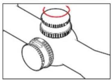
natural_image
Diagram of two mechanical components with a red circular mark on top (no text or symbols)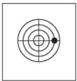
natural_image
Simple concentric circle diagram with a central dot and crosshairs (no text or symbols)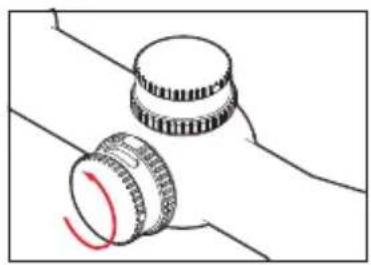
natural_image
Diagram of two mechanical components with a red curved arrow indicating rotation (no text or symbols)
natural_image
Simple concentric circle diagram with crosshair and central dot (no text or symbols)
natural_image
Diagram of two mechanical components with a red-handled ring, no text or symbols present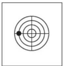
natural_image
Simple concentric circle diagram with a single black dot at the center (no text or symbols)
natural_image
Diagram of two mechanical components with a red curved arrow indicating rotation (no text or symbols)- Top knurled dial with
a. Hexagon socket screws for fixing - Bottom knurled dial with
b. Locking position display
c. Viewing window - Scale ring with engraving
ADDITIONAL ITEMS SUPPLIED
- Allen key SW 2mm
CONTENTS
Delivery condition 10
Locking and unlocking the adjustment mechanism......10
Zeroing....11
Correction with standard mounting.... 11
Correction with pre-tilted mounting 13
Extending the elevation turret correction range.... 14
Zeroing the scale 15
Note:
For further details on using your Leica Magnus telescopic sight, refer to the manual.
DELIVERY CONDITION
When delivered, the reticule on your Leica telescopic sight is set to the mechanical center of the total adjustment range. The reticule adjustment scale ring (3) is at a value of "5". This setting guarantees a maximum adjustment range (approx. 50cm / 100m) in both directions when zeroing the telescopic sight on the weapon.
LOCKING AND UNLOCKING THE ADJUSTMENT MECHANISM
The elevation turret on Leica Magnus telescopic sights has a lock to prevent unintentional adjustment. To lock and unlock, the bottom knurled dial (2) can be turned by 90° clockwise and anticlockwise. The current locking position is clearly indicated by a corresponding symbol (2.b).
Note:
Note that the bottom knurled dial (2) can be turned slightly beyond the detent positions to guarantee that it always engages clearly.
ZERoING
Mount your telescopic sight (see telescopic sight manual, p. 6). Make sure the weapon and the telescopic sight are as parallel as possible, so that you need to use the smallest possible adjustment range for zeroing correction.
CoRRECTIoN with STANDARD MoUNTING
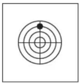
- Aim the weapon so that when you look through the barrel the center of the target is visible in the middle of the barrel. To do this, you should ideally remove the breech.
-
Unlock the elevation turret by turning the bottom knurled dial (2), so that the open padlock pictogram is towards the eyepiece.
-
Look through the mounted telescopic sight and correct the variation in the target position from the center of the target by turning the vertical and/or horizontal adjustment mechanism. Make sure that you do not change the position of the weapon.
- Then check again that the target pin and the center of the barrel are centered and that they coincide on the target.
natural_image
Simple target diagram with concentric circles and a central dot (no text or labels)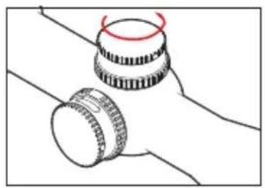
natural_image
Diagram of two mechanical components with a red circular mark on their top (no text or symbols)
natural_image
Simple concentric circle diagram with a central dot and crosshairs (no text or symbols)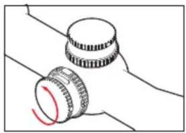
natural_image
Simple line drawing of two mechanical components with a red curved mark, no text or symbols present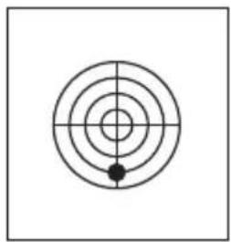
natural_image
Simple concentric circle diagram with crosshair and central dot (no text or symbols)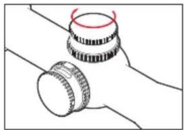
natural_image
Simple line drawing of two mechanical components with no text or symbols
natural_image
Simple concentric circle diagram with a single black dot at the center (no text or symbols)
natural_image
Diagram of two mechanical components with a red curved arrow indicating rotation (no text or symbols)-
Fire a test shot.
-
Repeat the procedure described above until any remaining variations in the point of impact have been eliminated.
Note:
Depending on the mounting, after zeroing a limited adjustment range may be available for actual use. If the total adjustment range is not sufficient, it can be extended in the following ways:
a. Use appropriate pre-tilted mounting We recommend using a mounting pre-tilted by around 10 MOA. This mounting provides you with around 29cm on a 100m adjustment range for use.
CORRECTION WITH PRE-TILTED MOUNTING
- Mount your telescopic sight using a pre-tilted mounting (for example 10 MOA).
- Unlock the elevation turret by turning the bottom knurled dial (2).
- Turn the top knurled dial (1) until the scale shows a value of "2.1 (21)". (50-29=21).
- Unlock the elevation turret by turning the bottom knurled dial (2).
- Loosen the clamping screws (1.a)
- Lift the top knurled dial (1) inc. scale ring (3) until it is no longer engaged.
- Turn the top knurled dial (1) until the scale shows a value of "5".
- Now press the top knurled dial (1) right down and hold it in place.
- Securely tighten the clamping screws (1.a)
Now continue as described for rough correction with standard mounting.
b. Extending the elevation turret correction range
- Set the elevation turret to its default delivery condition (locked, scale value "5" (50 clicks)).
- Loosen the clamping screws (1.a).
- Lift the top knurled dial (1) inc. scale ring (3) until it is no longer engaged.
-
Now turn the top knurled dial (1) inc. scale ring (3) until it provides you with an additional adjustment range.
(For example: The number of clicks from the "5" position to the mechanical stop at "0" is not sufficient for zeroing. You turn the top knurled dial to the "7" position. You have thus gained 20cm of adjustment towards "0".) -
Now press the top knurled dial (1) right down and hold it in place.
- Securely tighten the clamping screws (1.a)
Note:
Extending the adjustment range for zeroing can result in a restricted adjustment range in actual use / when correcting the point of impact. If necessary, use a pre-tilted mounting as described under a) to achieve optimum results.
ZEROING THE SCALE
- The telescopic sight and weapon have been zeroed.
- Unlock the elevation turret by turning the bottom knurled dial (2).
- Loosen the clamping screws (1.a).
- Lift the top knurled dial (1) inc. scale ring (3) until it is no longer engaged.
- Now set the top knurled dial (1) inc. scale ring to the zero position, i.e. until the zero marker appears in the inspection window (2.c) and coincides with the index point (4).
- Now press the top knurled dial (1) right down and hold it in place.
- Securely tighten the clamping screws (2.a).
Note:
The zero position on the elevation turret scale should always correspond to your minimum zeroing distance as the elevation turret does not have a negative adjustment range.
LEICA ELEVATION TURRET BALLISTICS CALCULATOR
On the Leica Camera AG home page you will find our elevation turret ballistics calculator. This enables you to determine the relevant elevation turret adjustment values for various distances depending on the caliber and charge. To enjoy the full benefits of the Leica elevation turret easily and accurately, we recommend using this calculator.
LEICA INFoRMTIoN SERvICE
The Leica information service can provide you with an answer to any technical application questions relating to the Leica range either in writing, on the telephone or by e-mail.
Leica Camera AG
Information Service
PO Box 1180
D- 35599 Solms
For servicing your Leica equipment or in the event of damage, the Leica Camera AG Customer Care department or the repair service provided by authorized Leica agents in your country are available (see the warranty card for a list of addresses).
Leica Camera AG
Customer Care
natural_image
Simple target diagram with concentric circles and a central dot (no text or labels)
natural_image
Diagram of two mechanical components with a red circular mark on top (no text or symbols)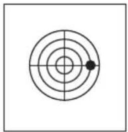
natural_image
Simple concentric circle diagram with a single black dot at the center (no text or symbols)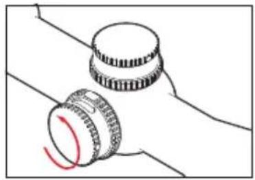
natural_image
Simple line drawing of two mechanical components with a red curved arrow indicating rotation (no text or symbols)
natural_image
Simple concentric circle diagram with crosshair and central dot (no text or symbols)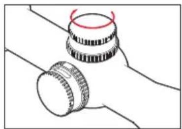
natural_image
Diagram of two mechanical components with a red-handled ring, no text or symbols present
natural_image
Simple concentric circle diagram with a single black dot at the center (no text or symbols)
natural_image
Diagram of two mechanical components with a red curved arrow indicating rotation (no text or symbols)natural_image
Simple target diagram with concentric circles and a central dot (no text or labels)
natural_image
Simple line drawing of two mechanical components with a red circular mark on top (no text or symbols)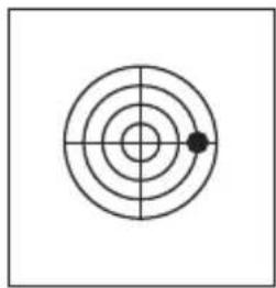
natural_image
Simple concentric circle diagram with a single black dot at the center (no text or symbols)
natural_image
Simple line drawing of two mechanical components with a red curved arrow indicating rotation (no text or symbols)
natural_image
Simple concentric circle diagram with crosshair lines and a central dot (no text or symbols)
natural_image
Simple line drawing of two mechanical components with no text or symbols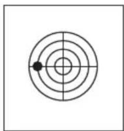
natural_image
Simple concentric circle diagram with a single black dot at the center (no text or symbols)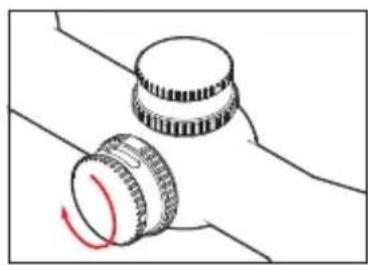
natural_image
Diagram of two mechanical components with a red curved arrow indicating rotation (no text or symbols)natural_image
Simple target diagram with concentric circles and a central dot (no text or labels)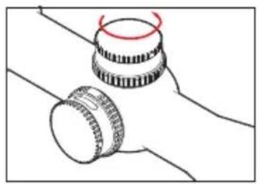
natural_image
Diagram of two mechanical components with a red circular motion indicator (no text or symbols)
natural_image
Simple concentric circle diagram with a central dot and crosshairs (no text or symbols)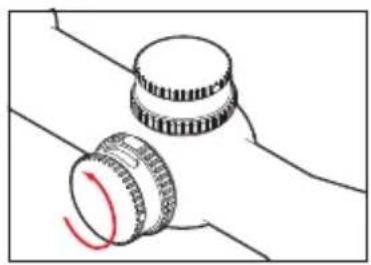
natural_image
Diagram of two mechanical components with a red curved arrow indicating rotation (no text or symbols)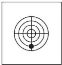
natural_image
Simple concentric circle diagram with crosshair and a small black dot at the center (no text or symbols)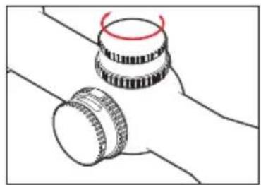
natural_image
Simple line drawing of two mechanical components with no text or symbols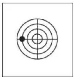
natural_image
Simple concentric circle diagram with a single black dot at the center (no text or symbols)
natural_image
Diagram of two mechanical components with a red curved arrow indicating rotation (no text or symbols)natural_image
Simple concentric circle diagram with a central dot and crosshairs, no text or symbols present.
natural_image
Diagram of two mechanical components with a red curved line indicating rotation (no text or symbols)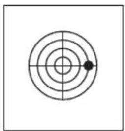
natural_image
Simple concentric circle diagram with a central dot and crosshairs (no text or symbols)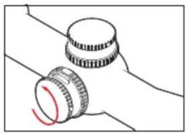
natural_image
Simple line drawing of two mechanical components with a red curved mark, no text or symbols present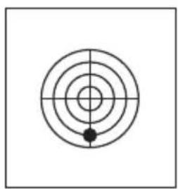
natural_image
Simple concentric circle diagram with a central crosshair and a black dot at the center (no text or symbols)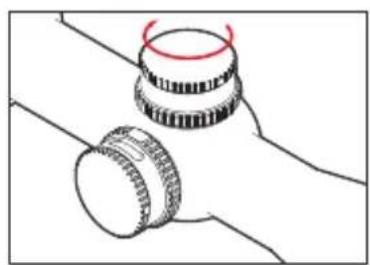
natural_image
Diagram of two mechanical components with no visible text or symbols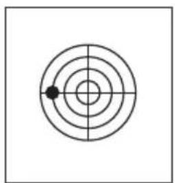
natural_image
Simple concentric circle diagram with a single black dot at the center (no text or symbols)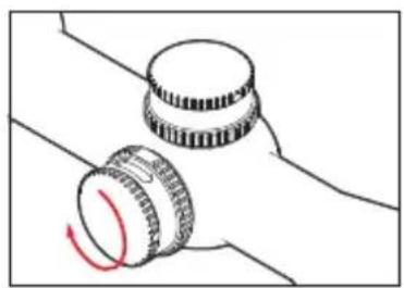
natural_image
Diagram of two mechanical components with a red curved arrow indicating rotation (no text or symbols)natural_image
Simple target symbol with concentric circles and a central crosshair (no text or labels)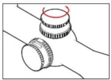
natural_image
Diagram of two mechanical components with a red circular mark on top (no text or symbols)
natural_image
Simple concentric circle diagram with a central dot and crosshairs (no text or symbols)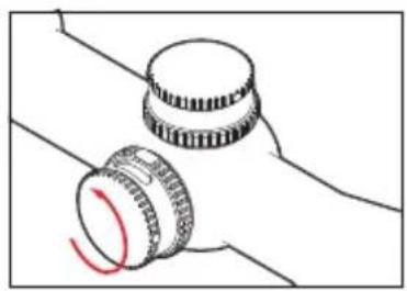
natural_image
Diagram of two mechanical components with a red curved arrow indicating rotation (no text or symbols)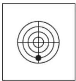
natural_image
Simple concentric circle diagram with a central dot and crosshairs, no text or symbols present.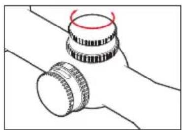
natural_image
Diagram of two mechanical components with a red circular motion indicator (no text or symbols)
natural_image
Simple concentric circle diagram with a single black dot at the center (no text or symbols)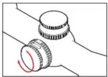
natural_image
Diagram of two mechanical components with a red curved arrow indicating rotation (no text or symbols)natural_image
Simple target diagram with concentric circles and a central dot (no text or labels)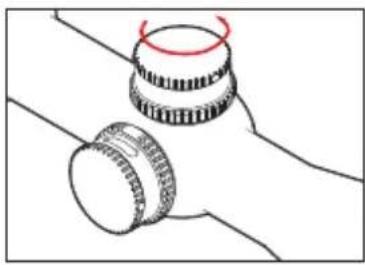
natural_image
Simple line drawing of two mechanical components with a red circular mark on top (no text or symbols)
natural_image
Simple concentric circle diagram with a single black dot at the center (no text or symbols)
natural_image
Simple line drawing of two mechanical components with a red curved arrow indicating rotation (no text or symbols)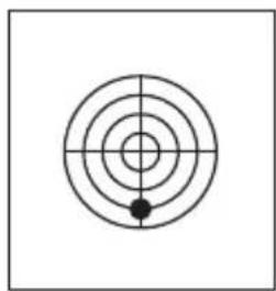
natural_image
Simple concentric circle diagram with crosshair lines and a central dot (no text or symbols)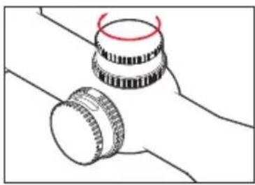
natural_image
Simple line drawing of two mechanical components with no text or symbols
natural_image
Simple concentric circle diagram with a single black dot at the center (no text or symbols)
natural_image
Diagram of two mechanical components with a red curved arrow indicating rotation (no text or symbols)
Brand : LEICA
Model : ASV
Category : Binoculars