PAM 220 - Measuring equipment BOSCH - Free user manual and instructions
Find the device manual for free PAM 220 BOSCH in PDF.
Frequently Asked Questions - PAM 220 BOSCH
User questions about PAM 220 BOSCH
0 question about this device. Answer the ones you know or ask your own.
Ask a new question about this device
Download the instructions for your Measuring equipment in PDF format for free! Find your manual PAM 220 - BOSCH and take your electronic device back in hand. On this page are published all the documents necessary for the use of your device. PAM 220 by BOSCH.
USER MANUAL PAM 220 BOSCH
Power Tools Division
70745 Leinfelden-Echterdingen
Germany
www.bosch-pt.com
1609 92A OGC (2014.03) T/178 WEU

PAM 220

BOSCH
Read and observe all instructions. SAVE THESE INSTRUCTIONS FOR FUTURE REFERENCE.
- Have the measuring tool repaired only through qualified specialists using original spare parts. This ensures that the safety of the measuring tool is maintained.
- Do not operate the measuring tool in explosive environments, such as in the presence of flammable liquids, gases or dusts. Sparks can be created in the measuring tool which may ignite the dust or fumes.
- When using the angle information provided by this tool to cut workpieces, always strictly observe the safety and working instructions of the saw being used, including those for positioning and clamping the workpiece. When the required angles can not be set on a certain saw or saw type, alternative sawing methods will need to be applied. Extremely acute (sharp) angles can be cut using a taper jig with a table saw or a circular saw.
Product Description and Specifications
Intended Use
The measuring tool is intended for measuring and transferring angles, calculating simple and compound metre angles, and checking and aligning horizontals and verticals.
Product Features
The numbering of the product features shown refers to the illustration of the measuring tool on the graphic page.
1 Fold-out leg
2 Leg extension
3 Base leg
4 Illuminated display
5 Spirit level for horizontal alignment
6 Spirit level for vertical alignment
7 “ Compound MTR ” button
8 “ M T R ” button for simple litre
9 "Hold/Clear" button
10 "180" button for supplementary angle
11 "On/Off" button
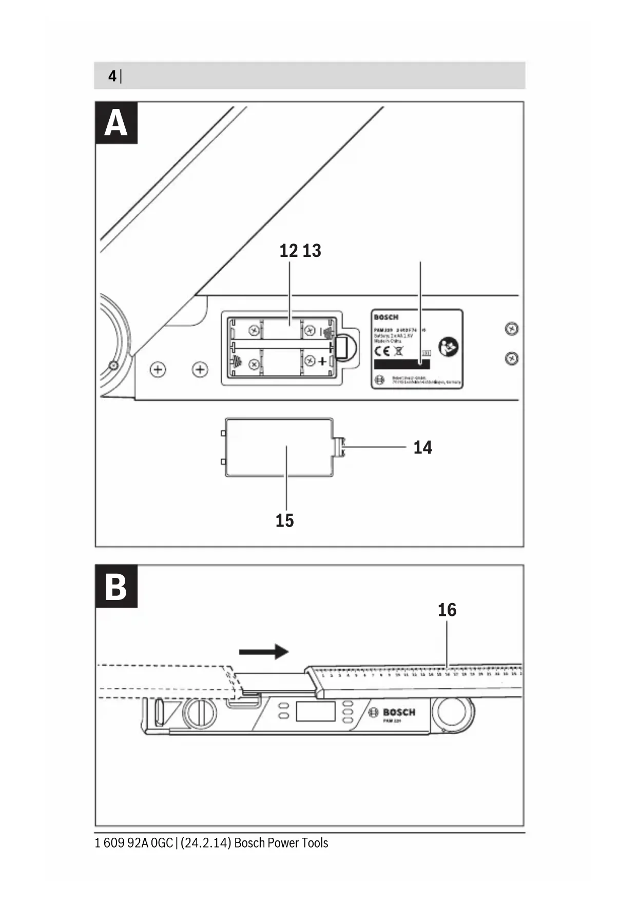
12 Battery compartment
13 Serial number
14 Latch of battery lid
15 Battery lid
16 Scale on leg extension
Display Elements
a Reading
b Battery charge control indicator
c Supplementary angle indicator "SUP"
d Spring angle indicator "SPR"
e Corner angle indicator "CNR"
f Mitre angle indicator "MTR"
g Bevel angle indicator "BVL"
h Memory indicator "HOLD"
Technical Data
| Digital Angle Measuring Device PAM 220 | |
| Article number | 3 603 F76 ... |
| Measuring range | 0° -220° |
| Measuring accuracy | |
| - A n g l e | ±0.2° |
| - Spirit level | 1.5 mm/m |
| Calculated angle accuracy | ±0.1° |
The measuring tool can be clearly identified with the serial number 13 on the type plate.
| Digital Angle Measuring Device PAM 220 | |
| Operating temperature | -10 °C ... +50 °C |
| Storage temperature | -20 °C ... +70 °C |
| Batteries | 2x1.5 V LR6 (AA) |
| Operating time, approx. | 25 h |
| Automatic switch-off after approx. | 5 min |
| Leg length | 400 mm |
| Weight according to EPTA-Procedure 01/2003 | 0.9 kg |
| Dimensions | 425 x 41 x 58 mm |
| The measuring tool can be clearly identified with the serial number 13 on the type plate. | |
Assembly
Inserting/Replacing the Batteries (see figure A)
Using alkali-manganese or rechargeable batteries is recommended for operation of the measuring tool.
To open the battery lid 15, press the latch 14 and remove the battery lid. Insert the batteries/rechargeable batteries. When inserting, pay attention to the correct polarity according to the representation on the inside of the battery compartment.
When the battery low indicator b is indicated the first time in the display, measurements can be made for only about 1 - 2 hours.
When the battery low indicator b flashes, the batteries/rechargeable batteries must be replaced. Measurements are no longer possible.
Always replace all batteries/rechargeable batteries at the same time. Do not use different brands or types of batteries/rechargeable batteries together.
- Remove the batteries/rechargeable batteries from the measuring tool when not using it for longer periods. When storing for longer periods, the batteries/rechargeable batteries can corrode and self-discharge.
Mounting the Leg Extension
Slide the leg extension 2 onto the front of the fold-out leg 1. Slide the leg extension as far as necessary over the joint of the measuring tool.
Operation
Initial Operation
Protect the measuring tool against moisture and direct sun light.
- Do not subject the measuring tool to extreme temperatures or variations in temperature. As an example, do not leave it in vehicles for a long time. In case of large variations in temperature, allow the measuring tool to adjust to the ambient temperature before putting it into operation. In case of extreme temperatures or variations in temperature, the accuracy of the measuring tool can be impaired.
The contact surfaces and contact edges of the measuring tool must be clean. Protect the measuring tool against impact and shock.
Debris particles or deformations can lead to faulty measurements.
Switching On and Off
To switch on the measuring tool, press the "On/Off" button 11. Once switched on, the measuring tool is in "normal measuring mode".
To switch off the measuring tool, press the "On/Off" button 11.
When no activity is performed on the measuring tool for approx. 5 minutes, the measuring tool automatically switches off to save the batteries.
Aligning with the Spirit Levels
The measuring tool can be aligned horizontally with spirit level 5 and vertically with spirit level 6.
The measuring tool can also be used as a carpenter's spirit level for checking vertical and horizontal lines. For this, place or hold the measuring tool against the surface subject to checking.
26 | English
"Normal Measuring Mode"
After switching on, the measuring tool is always in normal measuring mode.
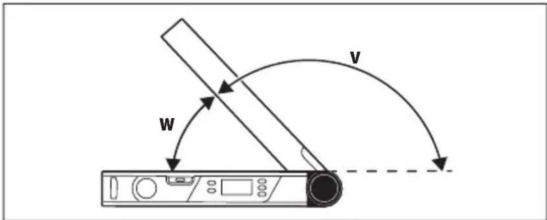
Measuring Angles (see figures C-E)
Place the fold-out leg 1 and the base leg 3 flat on the surfaces adjacent to the angle. The displayed measuring value a corresponds with the interior angle w between the base leg and the fold-out leg.
This measured value is shown on the display 4 until you change the angle between fold-out leg 1 and base leg 3.
Transferring Angles (see figure C)
Measure the angle to be transferred by applying the base leg and the fold-out leg to the reference angle.
Place the measuring tool in the desired position against the workpiece. Use the legs as a straight edge to transfer the angle.
Ensure that the fold-out and base legs are not moved during transfer.
Marking Angles (see figure D)
Open the fold-out leg and the base leg until the required angle is indicated in the display a.
Place the measuring tool in the desired position against the workpiece. Use the legs as a straight edge to transfer the angle.
Storing the Measured Value ("Hold/Clear")
To store the current measured value ("Hold"), press the "Hold/Clear" memory button 9.
The measured value is displayed until you press the "Hold/Clear" memory button 9 again, regardless of any movements of the base and fold-out legs.
Measuring with Leg Extension (see figures F-H)
The leg extension 2 makes it possible to measure angles when the contact surface is shorter than the fold-out leg 1.
Mount the leg extension 2 (see "Mounting the Leg Extension", page 25). Place the base leg 3 and the leg extension flat on the surfaces adjacent to the angle.
The reading of the angle w between base leg and fold-out leg is indicated in the display. The required angle v between base leg and leg extension is calculated as follows:
$$ \mathbf {v} = 1 8 0 ^ {\circ} - \mathbf {w} $$
If you press the "180°" button, the angle v (supplementary angle) you are looking for will be calculated and displayed.
Measuring "Simple Mitres"
"Simple litre" measurement is used to calculate the cutting angle "MTR" when two workpieces with the same litre have to form an outer angle x^ smaller than 180^ (e.g. for skirting boards, banister columns or picture frames).
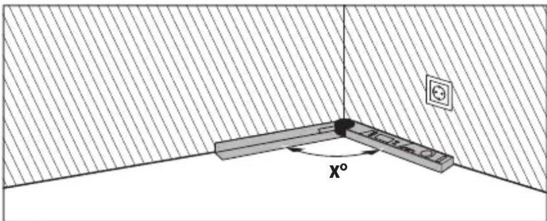
When workpieces are to be fitted into a corner (e.g. for floor trimmings), measure the corner angle x^ by applying the fold-out leg and the base leg. For given angles (e.g. picture frames), open the fold-out leg and the base leg until the desired angle is indicated in the display.
28|English
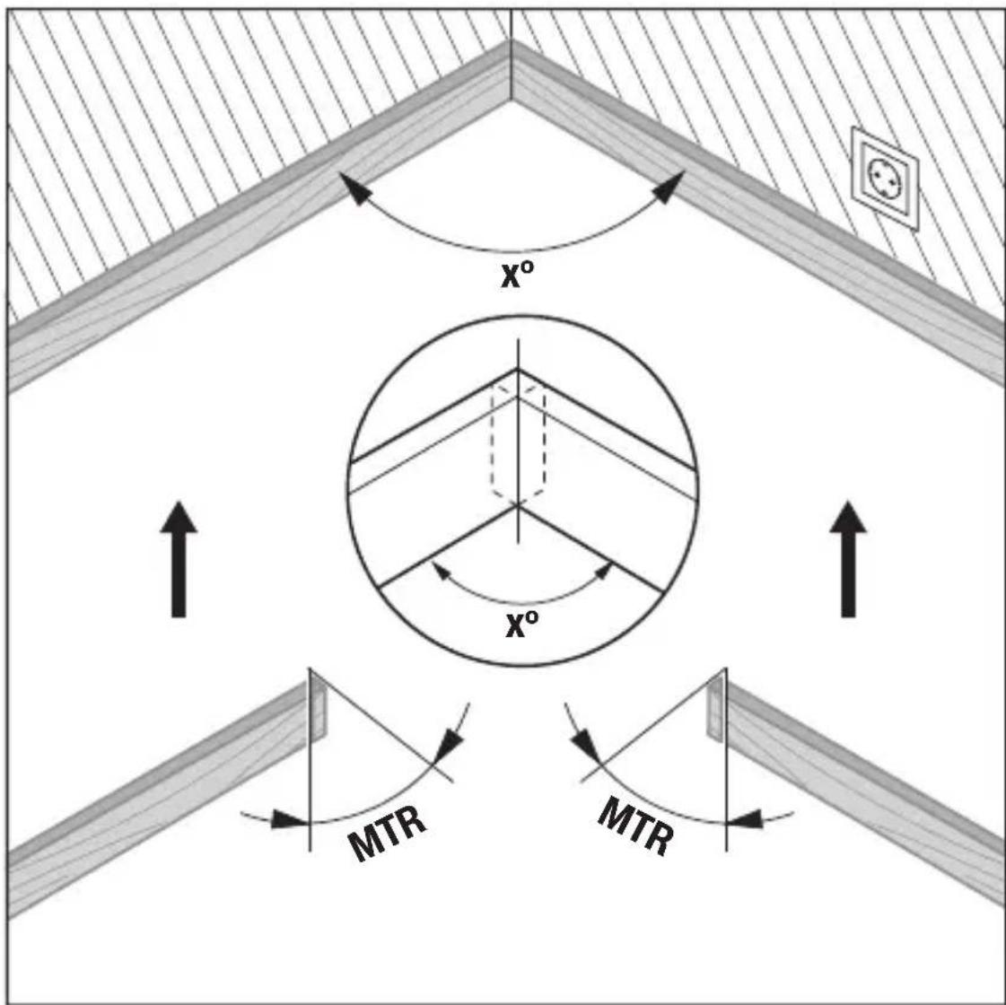
The litre angle "MTR", by which the two workpieces are to be shortened, is calculated. For these litre cuts, the saw blade is vertical to the workpiece (the bevel angle is 0^ ).
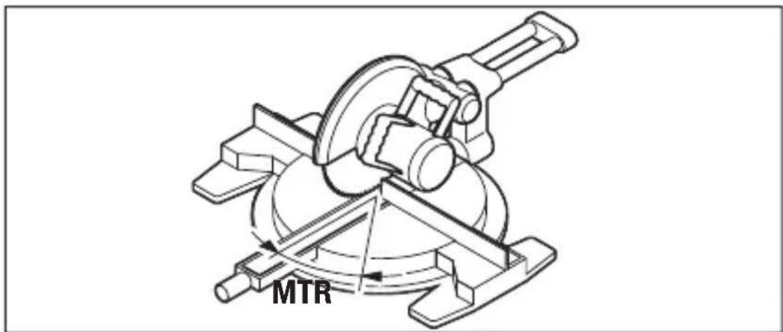
Press the "MTR" button 8. As long as you hold down the "MTR" button 8, the calculated horizontal litre angle "MTR", which has to be set on the litre saw, will be displayed. At the same time, the "MTR" indicator will light up in the display.
Note: The calculated litre angle "MTR" can only be taken over for chop and litre saws, for which the setting for vertical cuts is 0^ . When the setting for vertical cuts is 90^ , the angle for the saw must be calculated as follows:
90^ - indicated "MTR" angle = angle to be set on the saw.
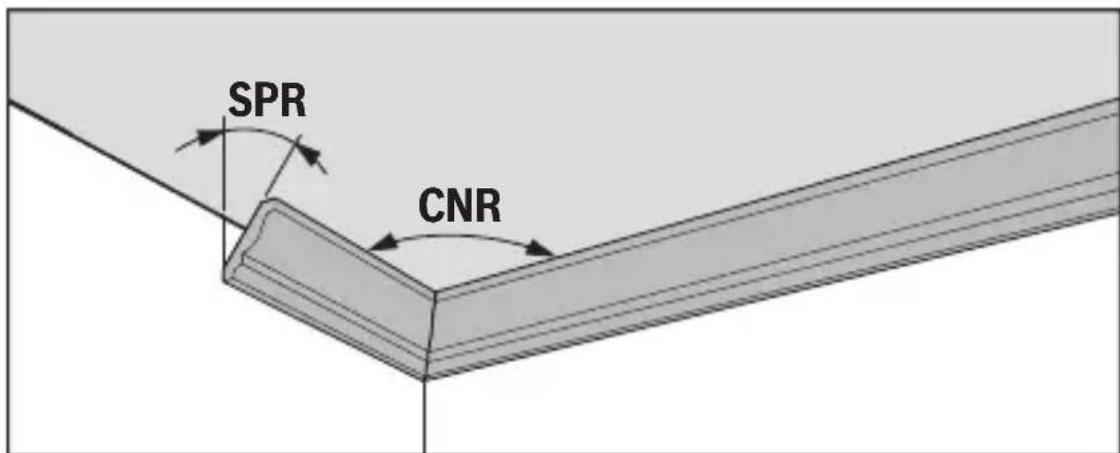
Measuring "Compound Mitres"
"Compound litre" measurement ("Compound MTR") is used to calculate horizontal and vertical litre angles when two workpieces with multiple angles (e.g. crown mouldings) have to join precisely.
First measure the spring angle (SPR) and the corner angle (CNR). The measuring tool will then calculate the litre angle (MTR) and the bevel angle (BVL).
Carry out the worksteps exactly in the given sequence.
"1. SPR": Storing the Spring Angle
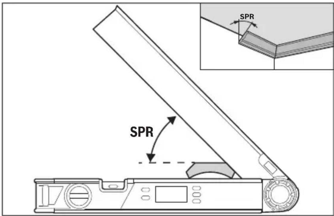
The spring angle can be stored as follows:
- Open the fold-out leg and base leg until the desired spring angle is shown on the display.
- Measure the spring angle if it is unknown. To do so, place the workpiece you want to measure between the fold-out leg and the base leg. If measurement is not possible with the measuring tool on especially narrow or small workpieces, use auxiliary equipment, e.g. a bevel, and then set the angle on the measuring tool.
Press button 7 to store the measured spring angle for the compound litre. "SPR" and the current angle will appear on the display.
"2. CNR": Storing the Corner Angle
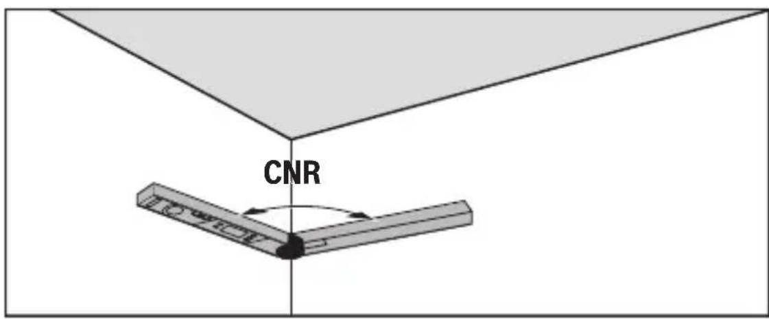
To measure the corner angle, place the fold-out and base legs flat against the walls or set a known corner angle on the measuring tool.
Press button 7 again to store the measured corner angle for the compound litre. "CNR" and the current angle will appear on the display.
"3. MTR": Calculating the Mitre Angle

Press button 7 again. "MTR" and the calculated litre angle for the chop and litre saw are indicated on the display.
The horizontal litre angle defines the rotation of the saw table (MTR).
"4. BVL": Calculating the Bevel Angle
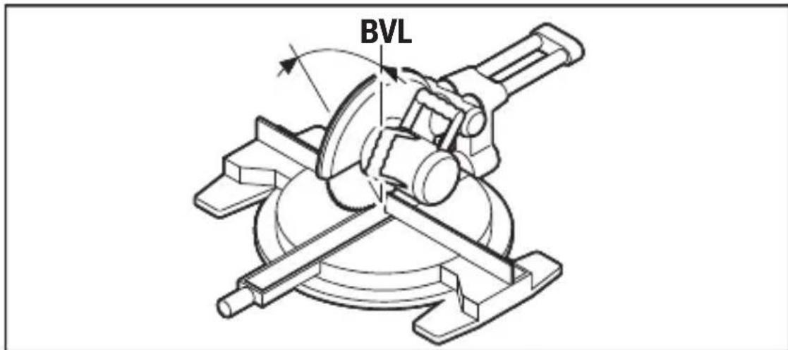
Press button 7 again. "BVL" and the calculated bevel angle for the chop and litre saw is indicated on the display.
The bevel angle defines the incline of the saw table (BVL).
Notes on "Compound Mitre" Operating Mode
The calculated litre angle "MTR" can only be taken over for chop and litre saws, for which the setting for vertical cuts is 0^ . When the setting for vertical cuts is 90^ , the angle for the saw must be calculated as follows: 90^ - indicated "MTR" angle = angle to be set on the saw.
Maintenance and Service
Maintenance and Cleaning
Keep the measuring tool clean at all times.
Do not immerse the measuring tool in water or other fluids.
Wipe off debris using a moist and soft cloth. Do not use any cleaning agents or solvents.
When the measuring tool is exposed to rain for an extended period, its function may be impaired. However, after completely drying off, the measuring tool is ready for operation. No calibration is required.
After-sales Service and Application Service
Our after-sales service responds to your questions concerning maintenance and repair of your product as well as spare parts. Exploded views and information on spare parts can also be found under:
www.bosch-pt.com
Bosch's application service team will gladly answer questions concerning our products and their accessories.
In all correspondence and spare parts orders, please always include the 10-digit article number given on the type plate of the measuring tool.
Great Britain
Robert Bosch Ltd. (B.S.C.)
P.O.Box 98
Broadwater Park
North Orbital Road
Denham
Uxbridge
UB95HJ
At www.bosch-pt.co.uk you can order spare parts or arrange the collection of a product in need of servicing or repair.
Tel. Service: (0844) 7360109
E-Mail: boschservicecentre@bosch.com
Ireland
Origo Ltd.
Unit 23 Magna Drive
Magna Business Park
City West
Dublin 24
Tel. Service: (01) 4666700
Fax: (01) 4666888
Australia, New Zealand and Pacific Islands
Robert Bosch Australia Pty. Ltd.
Power Tools
Locked Bag 66
Clayton South VIC 3169
Customer Contact Center
Inside Australia:
Phone: (01300) 307044
Fax: (01300) 307045
Inside New Zealand:
Phone: (0800) 543353
Fax: (0800) 428570
Outside AU and NZ:
Phone: +61 395415555
www.bosch.com.au
Republic of South Africa
Customer service
Hotline: (011) 6519600
Gauteng - BSC Service Centre
35 Roper Street, New Centre
Johannesburg
Tel.: (011) 4939375
Fax: (011) 4930126
E-Mail: bsctools@icon.co.za
KZN - BSC Service Centre
Unit E, Almar Centre
143 Crompton Street
Pinetown
Tel.: (031) 7012120
Fax: (031) 7012446
E-Mail: bsc.dur@za.bosch.com
Western Cape - BSC Service Centre
Democracy Way, Prosperity Park
Milnerton
Tel.: (021) 5512577
Fax: (021) 5513223
E-Mail: bsc@zsd.co.za
Bosch Headquarters
Midrand, Gauteng
Tel.: (011) 6519600
Fax: (011) 6519880
E-Mail: rbsa-hq.pts@za.bosch.com
Disposal
Measuring tools, accessories and packaging should be sorted for environmental-friendly recycling.
Do not dispose of measuring tools and batteries/rechargeable batteries into household waste!
Only for EC countries:
According to the European Guideline 2012/19/EU, measuring tools that are no longer usable, and according to the European Guideline 2006/66/EC, defective or used battery packs/batteries, must be collected separately and disposed of in an environmentally correct manner.
Battery packs/batteries:
Do not dispose of battery packs/batteries into household waste, fire or water. Battery packs/batteries should be collected, recycled or disposed of in an environmental-friendly manner.
Battery packs/batteries no longer suitable for use can be directly returned at:
Great Britain
Robert Bosch Ltd. (B.S.C.)
P.O.Box 98
Broadwater Park
North Orbital Road
Denham
Uxbridge
UB95HJ
At www.bosch-pt.co.uk you can order spare parts or arrange the collection of a product in need of servicing or repair.
Tel. Service: (0844) 7360109
E-Mail: boschservicecentre@bosch.com
Subject to change without notice.
Français
Robert Bosch (France) S.A.S.